25 minute read
OPERATING PROCEDURE (CONT’D)


Operating On Slopes (Cont’d)
When operating on a slope, level the work area before beginning [Figure 181]
If this is not possible, the following procedures should be used:
Do not work on slopes which are over 15 degrees. Use a slow work cycle.
Avoid working with the tracks across the slope. This will reduce stability and increase the tendency for the machine to slide. Position the excavator with the blade downhill and lowered.
Avoid swinging or extending the bucket more than necessary in a down hill direction. When you must swing the bucket downhill, keep the arm low and skid the bucket downhill.
When working with the bucket on the uphill side, keep the bucket as close to the ground as possible. Dump the spoil far enough away from the trench or hole to prevent the possibility of a cave in.
To brake the machine when going down a slope, move the steering levers (Item 1) [Figure 182] to the NEUTRAL position. This will engage the hydrostatic braking.

When the engine stops on a slope, move the steering levers to the NEUTRAL position. Lower the boom / bucket to the ground.
NOTE: If the engine stops, the boom / bucket (attachments) can be lowered to the ground using hydraulic pressure which is stored in the accumulator.
The console must be in the locked down position, and the key switch in the ON position.
Use the control lever to lower the boom.
Start the engine and resume operation.
OPERATING PROCEDURE (CONT’D)
Operating In Water
Mud and water should be removed from the machine before parking. In freezing temperatures, park the machine on boards or concrete to prevent the track or undercarriage from freezing to the ground and preventing machine movement.
Maximum Water Level
Do not operate or immerse the excavator in water higher than the bottom of the swing bearing [Figure 183]
Grease the excavator when it has been operated or immersed in water for a period of time. Greasing forces the water out of the lubrication areas.
Water must be removed from the cylinder rods. If water freezes to the cylinder rod, the cylinder seals can be damaged when the rod is retracted.

OPERATING PROCEDURE (CONT’D)
Avoiding Track Damage
Mud and water should be removed from the machine before parking. In freezing temperatures, park the machine on boards or concrete to prevent the track or undercarriage from freezing to the ground and preventing machine movement.
Some Cause Of Track Damage:
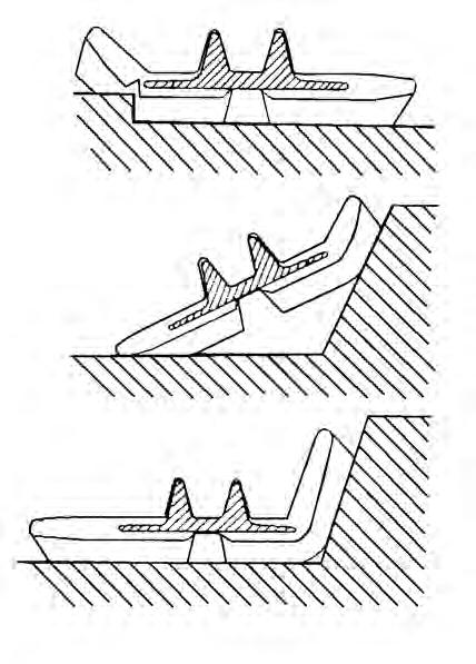
Figure 184
Incorrect track tension: When the rubber track is detracting, the idler or sprocket rides on the projections of the embedded metal [Figure 184] causing the embedded metal to be exposed to corrosion. (See TRACK TENSION on Page 176.)
If rubber track is clogged with stones or foreign objects, these can get wedged between the sprocket / rollers and cause detracting and track stress.
When moisture invades through cuts on the track, the embedded steel cords will corrode. The deterioration of the design strength may lead to the breaking of the steel cords.
Figure 185
When rubber tracks drive over projections or sharp objects in the field, the concentrated forces applied cause cuts on the lug side rubber surface [Figure 185]. In case of making turns on projections, the lug side rubber surface will have an even higher chance to be cut. If the cuts run through the embedded steel cords, it might result in the steel cords' breakage due to their corrosion.

Avoid quick turns on bumpy and rocky fields.
Driving over sharp objects should be avoided. If this is impossible, do not make turns while driving over sharp objects.
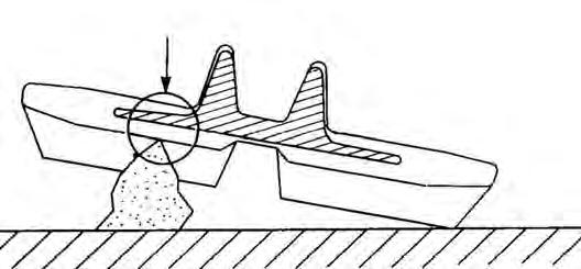
Figure 186
When rubber tracks drive over sharp projections, intensive stress is applied to the lug side rubber surface, especially at the edges of embedded metals, causing cracks and cuts in the area around the embedded metals [Figure 186]
Avoid extensive stress applied to the lug root where metals are embedded. Operators should try to avoid driving over stumps and ridges.
Depth Check
Setup / Calibration
NOTE:The machine shown in the photos may be different than your machine and this manual but the procedure is the same for all models.
Warning
Avoid Injury Or Death
When an engine is running in an enclosed area, fresh air must be added to avoid concentration of exhaust fumes. If the engine is stationary, vent the exhaust outside. Exhaust fumes contain odorless, invisible gases which can kill without warning.
W-2050-0807
NOTE:When the Depth Check kit was initially installed, the machine should have had the setup / calibration procedure performed. But with usage of any attachment, components and the cutting surfaces wear. The accuracy of the Depth Check system is affected by the wear of these components. If loss of accuracy is noticed, re-calibrate the attachment to reset the dimensions needed for the Depth Check system to operate correctly.
Move the machine to an open area where the boom and arm can be repositioned and there is fresh air as the engine will need to be operating during this procedure.
Park the machine on a flat level surface.
The calibration procedure is a two person operation. One person must remain in the cab to enter data into the deluxe display panel while a second person takes measurements from outside the machine. Make sure the second person is away from the machine when moving any of the work group components (boom, arm, bucket, etc.).
Warning
Keep all bystanders 6 m (20 ft) away from equipment when operating.
W-2268-0910
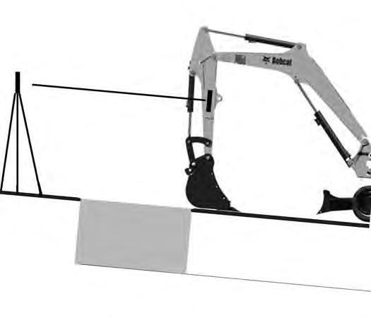
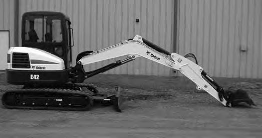
Position the excavator [Figure 187] as shown so the second person can install the magnetic tools, the plumb bob and do measurements for calibrating the system.
Two magnetic mounted tools are included with the kit for positioning the boom, arm and bucket for calibration. These magnetic tools need to be kept with the machine as the Depth Check system should be re-calibrated on a yearly basis or sooner if slight changes in accuracy are noticed.
The Depth Check system sensors are designed for high angle stability and temperature ranges. However, with the use of any mechanical components (boom, arm, bucket, etc.), there is wear on the components with normal usage and this will affect the accuracy of the Depth Check system over time. Also, if any structural changes are made, components replaced or a new attachment is installed on the excavator, it will require the setup / calibration procedure to be performed.
DEPTH CHECK (CONT’D)
Setup / Calibration (Cont’d)
Position the excavator with the bucket fully rolled out and the arm fully extended. Position the workgroup so the distance from the ground to the two magnetic sensors (Item 1 and 2) [Figure 190] is identical.
NOTE:It may be necessary on some machines to lower the blade to raise the front of the excavator up slightly to position the boom pivot pin so that the boom and arm pivot points will be parallel to the ground when calibrating.
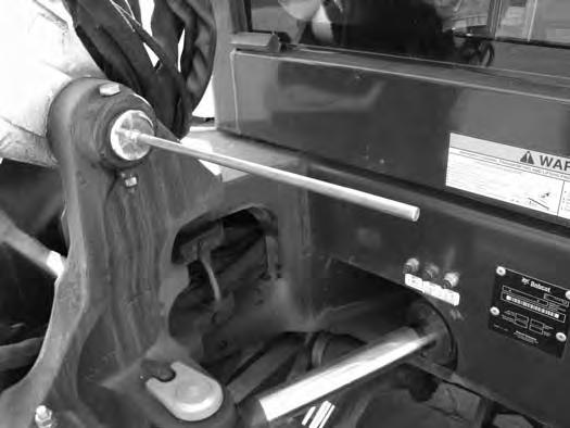
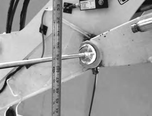
Measure the distance from the center of the boom magnetic tool (Item 1) [Figure 191] to the ground. Measure as close to the boom as possible without interference from components between the boom and the ground. The closer to the boom the measurement is taken, the more accurate the measurement should be. (A laser level can also be used for locating the centerlines of the magnetic tools as this will eliminate any possible variation in the measurements to the ground.)

DEPTH CHECK (CONT’D)
Setup / Calibration (Cont’d)
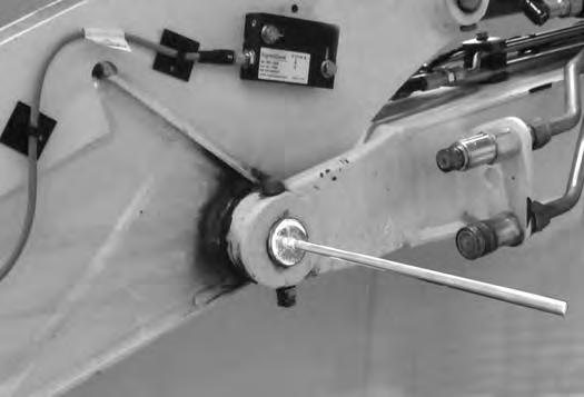
Measure the distance from the center of the arm magnetic tool (Item 1) [Figure 192] to the ground and make sure both measurements are the same. Adjust the boom up or down as needed and remeasure until both dimensions are the same between [Figure 191] and [Figure 192].
Once the dimensions are identical, the second person in the cab will need to enter the setup / calibration information into the dash panel. (The accuracy of these dimensions affect the accuracy of the Depth Check.)
NOTE:Make sure there is no cylinder drift that could affect the calibration accuracy. The second person needs to enter the information into the display panel in a timely manor.
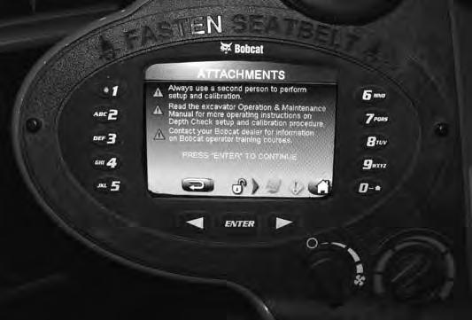
Scroll through the dash panel by pressing the left arrow (Item A) or the right arrow (Item B) until the [ATTACHMENTS] screen is displayed. Press the [ENTER] button (Item C) [Figure 193]
NOTE:If the Depth Check settings have been locked, enter the owner password to access the setup / calibration procedure.
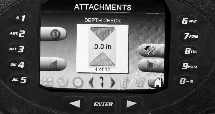
On the [ATTACHMENTS] screen, use the left arrow button (Item 4) or the right arrow button (Item 9) and scroll to the [ATTACHMENT DEPTH CHECK] screen shown here. Press the [ENTER] button (Item C) or button (Item 8) [Figure 194] to access the [DEPTH CHECK SETUP] screen.

DEPTH CHECK (CONT’D)
Setup / Calibration (Cont’d)
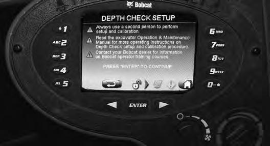
One of three different screens can appear. Which ever screen appears, press button (Item 2) [Figure 195] to access the [DEPTH CHECK SETUP] screen.
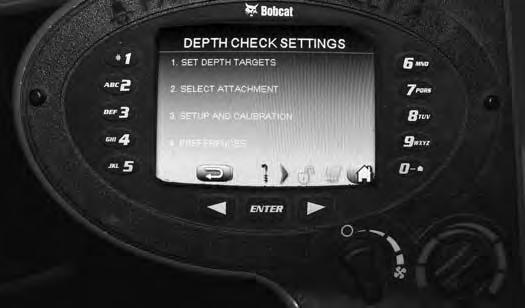
NOTE: The units of measure can be set in either millimeters or inches. Press button (Item 4) to enter the Preferences screen and select meters, millimeters, feet or inches, then press the arrow button (Item A) [Figure 196] to go back to the above screen.

NOTE:If the Depth Check settings have been locked, enter the owner password to access the setup / calibration procedure.
Press the button (Item 3) [Figure 196] for setup / calibration mode.

DEPTH CHECK (CONT’D)

Setup / Calibration (Cont’d)
With the boom leveled [Figure 191] and [Figure 192], press the [ENTER] button (Item C) [Figure 199] to store this information into the setup / calibration settings.

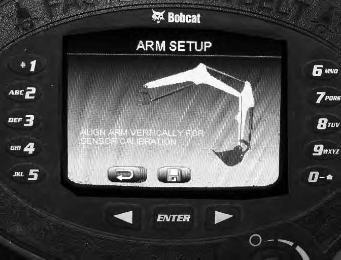
The next setup / calibration step will be for Arm Setup. This will require a plumb bob to make sure the arm is in the correct vertical position.
NOTE:If a plumb bob is not available, fishing line or a string with a heavy nut or two tied on one end of the string can be used in place of a plumb bob.
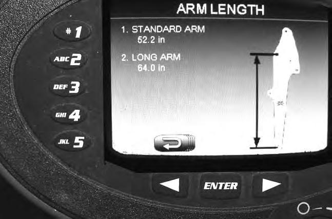
The system needs to know if the machine is equipped with a standard arm or the long arm option. The excavator ECU knows the machine model so the dimensions for the two arms is shown on the screen. For the Standard Arm, press (Item 1), for Long Arm, press (Item 2). Press the [ENTER] button (Item C) [Figure 201] to store this information into the setup / calibration settings.
Have the second person in the cab and press the [2. ARM SETUP] (Item 2) [Figure 200]
DEPTH CHECK (CONT’D)
Setup / Calibration (Cont’d)
Place the plumb bob (Item 1) [Figure 202] on the magnetic tool that is installed on the arm pin. Raise the boom and move the arm until the arm is vertical.
Move the arm until the plumb bob line is centered on the bucket pivot pin (Item 2) [Figure 202] (The accuracy of the arm being vertical affects the accuracy of the Depth Check.)

With the arm vertical [Figure 202], press the [ENTER] button (Item C) [Figure 203] to store this information into the setup / calibration settings.

Press
204]
DEPTH CHECK (CONT’D)
Setup / Calibration (Cont’d)
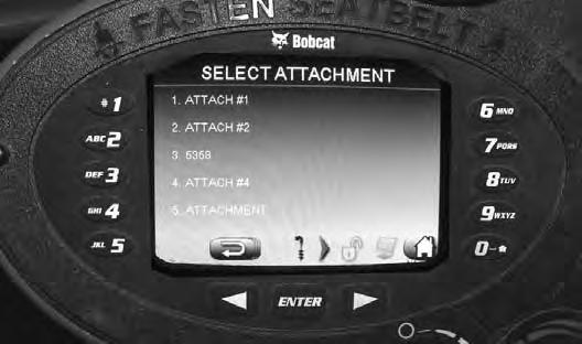
Select one of the attachments (Item 1 - 5) [Figure 205] from the list.
NOTE:Up to five different attachments can be named, setup / calibrated and stored or removed to make room for a new attachment. When switching between attachments, just select the desired attachment and as long as it was correctly setup, the Depth Check system will have the information needed for that attachment.
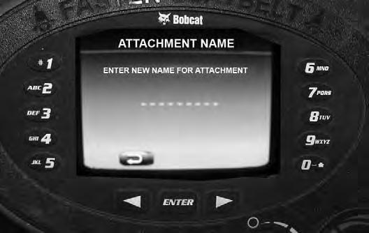
Use the key pads (Item 1 through 0) and enter a name or number for the attachment being setup. Press the [ENTER] button (Item C) [Figure 207] to save the name. (To add the name, press the key pad multiple times until the correct letter or number appears on the screen for the attachment name.)
If setting up additional attachments, select (Items 2 through Item 5) [Figure 205] and add the additional attachment names.
If setting up and calibrating multiple attachments at the same time, add all the attachment names into the system before doing the measurements. It will be more convenient when it comes time to add the dimensions.
Press the arrow button (Item A) [Figure 206] and go back to the [ATTACHMENT SETUP] screen.
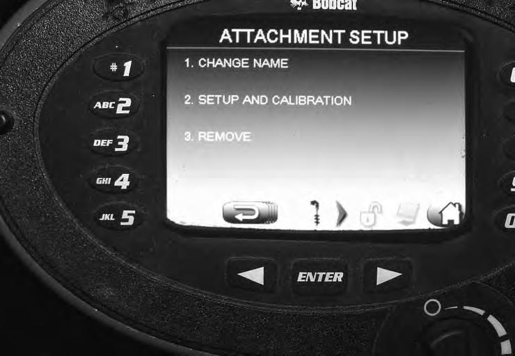
Press the [2. SETUP AND CALIBRATION] button (Item 2) [Figure 206]
On the [ATTACHMENT SETUP] screen, you can select [1. CHANGE NAME] (Item 1), [2. SETUP AND CALIBRATION] (Item 2) or [3. REMOVE] (Item 3) [Figure 206] the attachment from the saved list.
Select [1. CHANGE NAME] (Item 1) [Figure 206] to open the attachment name screen.
Name Examples: 24” bucket, 30” bucket, Auger, etc.
DEPTH CHECK (CONT’D)
Setup / Calibration (Cont’d)
Figure 208
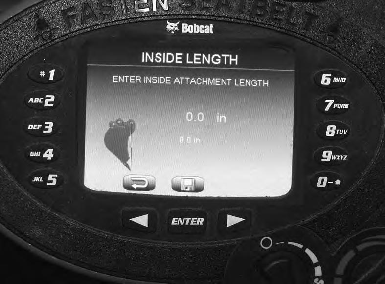
The inside length screen [Figure 208] is where the first attachment dimensions will be added from the information determined in step [Figure 209]
Position the bucket vertical. Use the plumb bob to locate the furtherest vertical cutting point (Item 1) from the center of the bucket pin (Item 2) [Figure 209]

Set the tip of the bucket (Item 1) on the ground ensuring that everything is still vertical. Using a tape measure, measure the distance between the cutting edge (Item 1) and the center of the bucket pin (Item 2) [Figure 209].
NOTE: With usage of any attachment, the cutting surfaces wear. Example: The cutting edge (Item 1) [Figure 209] wears with the use of the bucket. The accuracy of the Depth Check system is affected by the wear of these components. If loss of accuracy is noticed, recalibrate the attachment to reset the dimensions needed for the Depth Check system to operate correctly.
The [INSIDE LENGTH] screen [Figure 208] is where the attachment dimensions will be added from the information determined in [Figure 209]
Using the key pad (Item 1 through 0) [Figure 208], enter this dimension. After the measurement is entered and verified, press the [ENTER] button (Item C) [Figure 208] As soon as the [ENTER] button is pressed, the [OUTSIDE LENGTH] [Figure 210] screen will be activated.
This two part step will measure the distance between the bucket pin (Item 2) [Figure 209] or the furthest point away from the bucket pin on any attachment used with the Depth Check system. We will be using a bucket as an example, but all attachments will be similar for this setup. (The accuracy of these dimensions affect the accuracy of the Depth Check.)
DEPTH CHECK (CONT’D)
Setup / Calibration (Cont’d)
Install a magnetic pin on the second bucket pin (Item 3) [Figure 209].
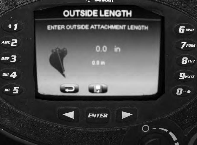
The next measurement is from the cutting edge (Item 4) to the center of the magnetic pin (Item 5) [Figure 209] for the outside length dimension.
Using the key pad (Item 1 through 0) [Figure 210] enter this dimension. After the measurement is entered and verified, press the [ENTER] button (Item C) [Figure 210]. As soon as the [ENTER] button is pressed, the screen will change to the [ATTACHMENT SETUP] screen [Figure 211]
Make sure the bucket is still vertical to the bucket pin (Item 2) and the cutting edge (or bucket teeth) (Item 1), and press the [ENTER] button (Item C) [Figure 211] to store the calibration information.
NOTE:If more than one attachment is being setup, the attachments can be changed on the arm and the additional attachment dimensions can also be entered. Always measure to the cutting / work tip on the attachment when measuring the dimensions to add to the inside and outside length screens for each new attachment. The Depth Check system uses these dimension along with the other setup points to calculate the tip position for Depth Check.

NOTE:When using an auger, it will not be as accurate as solid mounted attachments because all components are not rigidly mounted (auger bit has extra movement and rotation where the system is designed for fixed positions). When using the auger with the Depth Check system, enter zero for both attachment dimensions. When using the auger, try to keep the X-change horizontal to the ground during the dig cycle and monitor the screen depth. Using this setup should give fairly accurate Depth Check information for auger applications.
This finishes the SETUP / CALIBRATION procedure except if also installing a laser. (See If Using A Laser With Depth Check on Page 121.)
DEPTH CHECK (CONT’D)
Setup / Calibration (Cont’d)
If Using A Laser With Depth Check
Figure 212
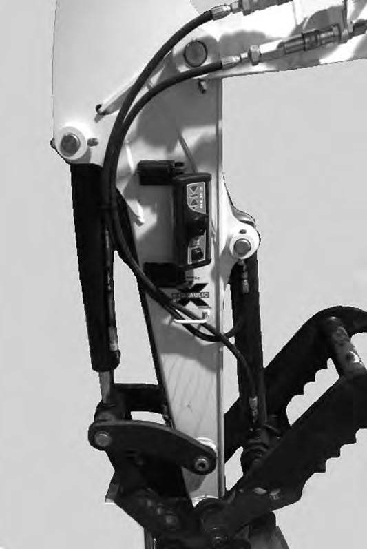
FOR model E45 with the standard arm ONLY; If using either of the laser receivers (Item 1) on machines that have the standard arm and a hydraulic clamp installed, you will need to check the length of the hydraulic clamp rod end hose (Item 2) [Figure 212] to make sure the existing hose does not interfere with the laser.
Measure the length of the hose (Item 2) [Figure 212]
Measure the hose from the rod end of the clamp cylinder (Item 2) [Figure 212] to the end of the hose at the coupler (Item 4) [Figure 213]
The hose length must be 1245 mm (49.0 in) or a new hose (P/N 7250478) must be ordered and installed.
If the hose is incorrect, it may interfere with the laser when the hydraulic clamp is operated and possibly knock the laser receiver off of the arm. OR, the laser can be mounted on the opposite side of the arm, then the hose will not interfere with the laser.
NOTE:For excavator equipped with a clamp, (or other options or configurations added to the arm that may interfere with the laser), make sure there is no hose to laser interference. Fully curl the arm and bucket and make sure the hoses do not interfere with the laser receiver during any arm and bucket movement. Adjust the position of the laser receiver if necessary to avoid any contact with the hoses.

For both standard and long arm models; When installing the laser receiver (Item 1), it should be installed as close as possible in line with the arm pin (Item 2) and the bucket pivot pin (Item 3) [Figure 213]
Position the laser (Item 1) approximately as shown. The dimension (Item A) will need to be added to the display screen. Measure from the center of the bucket pin (Item 3) up to the center of the laser receiver (Item 1) [Figure 213]
DEPTH CHECK (CONT’D)
Setup / Calibration (Cont’d)
If Using A Laser With Depth Check (Cont’d)
Figure 214
216
Initial Setup
The initial setup will describe adding and changing the Depth Check target settings, grade zone setting, warning zone setting, laser receiver, preferences (changing unit of measurement settings), and describe how the Depth Check system functions.
NOTE: The laser feature must be activated before you can enter the laser receiver position into the dash panel. See [Figure 228] for turning the laser ON and OFF.

Depth Check Settings
Figure 215
Using the left / right arrow buttons (Item A and B), toggle to the [ATTACHMENT DEPTH CHECK] screen [Figure 215]
Press the tool button (Item 8) or the [ENTER] button (Item C) [Figure 215] to go to the [DEPTH CHECK] screen [Figure 216] and [Figure 217]
The [DEPTH CHECK] screen [Figure 216] shows the following information. Press the numbered key pad to access each screen for setting the system:
(1) Re-bench: Used for setting the attachment start point to zero. (Example: Use surveyors elevation pin for the known depth to set zero.)
(2) Setup: Opens screen for selecting the following screens; Set Target Depth, Select Attachment, Setup and Calibration, and Preferences.
(3) Alarm: Sets the depth alarm to ON or OFF.
(4) Change Screens: Toggles through various depth screens; Depth Check, distance to target or grade check.
(6) Target Depth: Shows the depths for up to five pre-set depth settings.
(0) Home Screen: Press 0 to go back to the home screen on the display panel.
DEPTH CHECK (CONT’D)
Initial Setup (Cont’d)
Depth Check Settings (Cont’d)
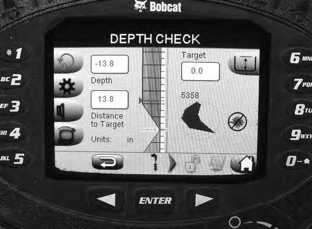
Figure 217
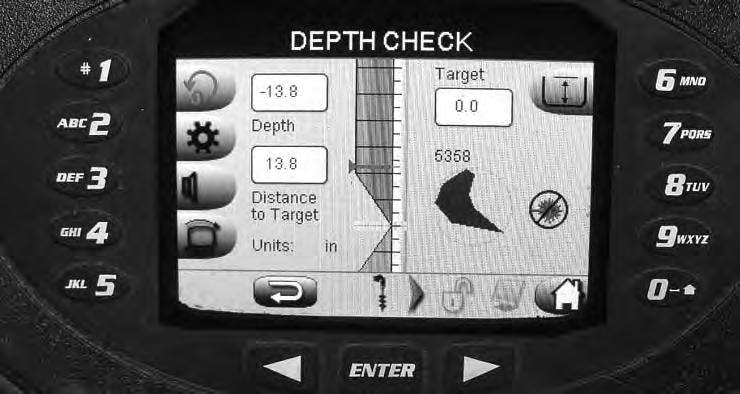
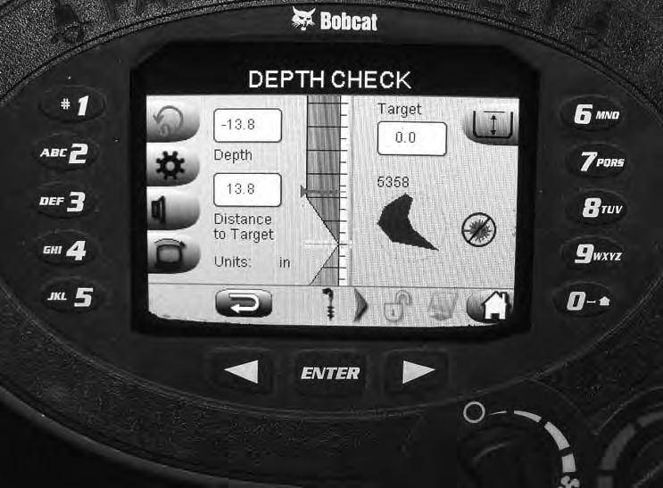
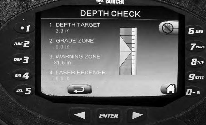
The [DEPTH CHECK] screen [Figure 217] shows the following information:

(A) Target (Dimension): The target is the depth to dig from an established starting point set by the operator. (Example: Desired dig depth from a surveyors elevation pin.)
(A1) Target (Bar Graph): The bar graph line shows where the target is at in relationship to the attachment position (Item B1).
(B) Depth (Dimension): This is the current depth of the attachment cutting edge.
(B1) Depth (Bar Graph): The bar graph line moves up and down and shows the position of attachment to the target (Item A1). (When the attachment gets close to the selected target depth, an audible alarm will start beeping. The closer the attachment gets to the target, the faster the beeps. When the alarm is continuous, you have reached the target depth. The alarm can be set ON or OFF by pressing the key pad number 3 [Figure 216]).
(C) Distance To Target (Dimension): The distance the attachment needs to travel to reach the selected target depth.
(D) Units: Shows the current selected unit of measure. (The units of measure can be set to meters, millimeters, feet or inches.)
(E) Name of attachment selected: Shows the name or the number of the selected attachment. (The attachment must be selected so that the Depth Check system knows what attachment is currently used for proper depth calculations.)
(F) Attachment: The screen uses a bucket to represent the attachment. The bucket will rotate to represent the position of the bucket (attachment) as the attachment is curled out or curled in. When the attachment is calibrated, it sets the position of bucket icon (F).
(G) Laser: The laser icon (Item G) will show if the laser is set to ON or OFF. (The laser as shown in [Figure 217] with the circle with the line through it represents the OFF position.)
DEPTH CHECK (CONT’D)
Initial Setup (Cont’d)
Depth Check Settings (Cont’d) the [SELECT
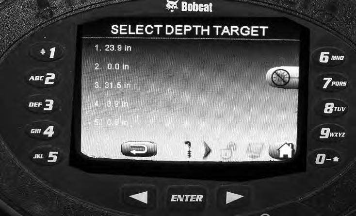
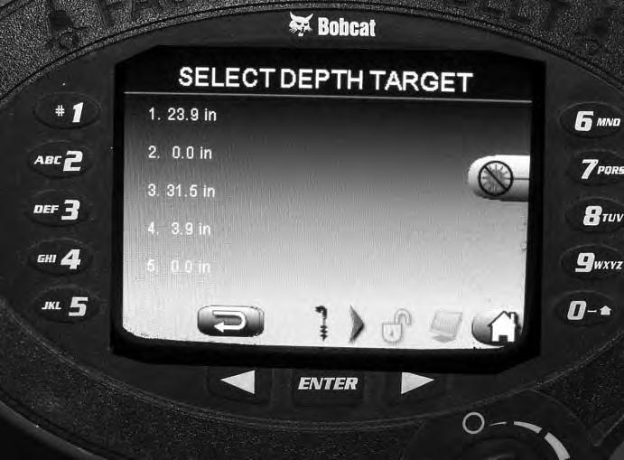
Five different depths can be pre-set and stored in the system.
Select (Item 1 through Item 5) [Figure 219] to select one of the existing depths.
Or, if a different depth is needed, press the return button (Item A) [Figure 219] to go back one screen, then press button (Item 2) [Figure 218] to go to the [DEPTH CHECK SETTINGS] screen [Figure 220]
DEPTH CHECK (CONT’D)
Initial Setup (Cont’d)
Depth Check Settings (Cont’d)

Figure 223
Use the key pads (Item 1 through 0) and enter the new target dimension. If the dimension entered is incorrect, press the arrow button (Item A) [Figure 223] to backspace the dimension.
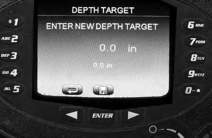
Press the [ENTER] button (Item C) [Figure 223] to save the depth dimension. (Dimensions shown in inches but can be set to feet, meters or millimeters. See [Figure 235].)
Grade Zone

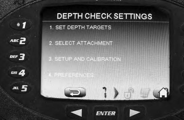
The Grade Zone sets the distance up or down from the target depth for when the warning alarm will start to be a continuous alarm. This will also increase the YELLOW highlighted area on the screen where the target zone is shown.
Press [GRADE ZONE] (Item 2) [Figure 225]
Grade zone area (Item 2A) [Figure 225] (in yellow on the display screen) is the area that will change with the dimensions as set in [Figure 226].
Press [1. SET DEPTH TARGETS] (Item 1) [Figure 224] to change to the next screen [Figure 225]
Use the key pads (Item 1 through 0) and enter the new grade zone dimension. If the dimension entered is incorrect, press the arrow button (Item A) [Figure 226] to backspace the dimension.
Press the [ENTER] button (Item C) [Figure 226] to save the grade zone dimension. (Dimensions shown in inches but can be set to feet, meters or millimeters. See [Figure 235].)
DEPTH CHECK (CONT’D)
Initial Setup (Cont’d)
Warning Zone
The Warning Zone sets the upper distance from the target depth when the warning alarm will start to beep. (The alarm will start beeping when getting close to the selected target depth. The closer to the target, the faster beeps until you reach the target depth, then it will be a continuous sound. If the bucket goes below the selected target depth, the beeps will be very fast until the bucket is raised above the target depth.)
Press [1. SET DEPTH TARGETS] (Item 1) [Figure 227] to change to the next screen [Figure 228]
Use the key pads (Item 1 through 0) and enter the new warning zone dimension. If the dimension entered is incorrect, press the arrow button (Item A) [Figure 229] to backspace the dimension.
Press the [ENTER] button (Item C) [Figure 229] to save the warning zone dimension. (Dimensions shown in inches but can be set to feet, meters or millimeters. See [Figure 235].)
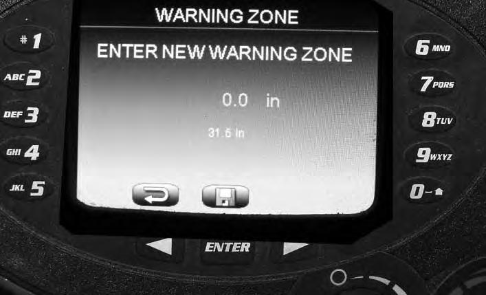
Press [3. WARNING ZONE] (Item 3) [Figure 228]
Press (Item 6) [Figure 228] to turn the laser ON or OFF.
DEPTH CHECK (CONT’D)
Initial Setup (Cont’d)
Laser Receiver Position On Arm
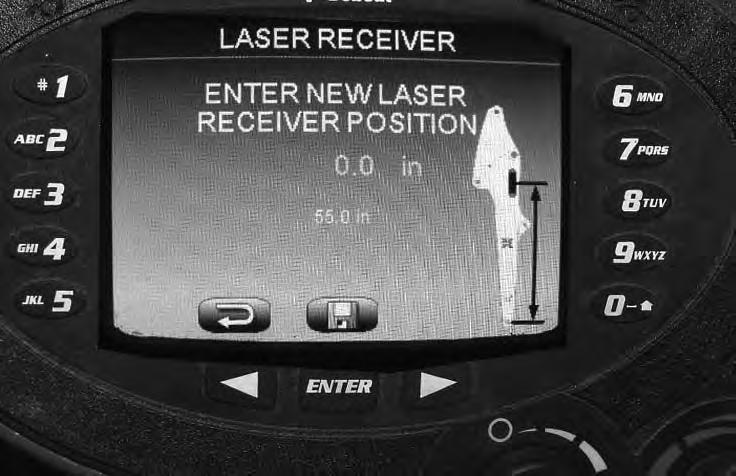
The Depth Check system needs to know the location of laser receiver mounted on the arm. This dimension is used along with the target depth to set the Depth Check position.
Activate the laser on the dash panel by pressing button (Item 6) [Figure 231]. Press once, laser ON. Press a second time, laser OFF.
Press [1. SET DEPTH TARGETS] (Item 1) [Figure 230] to change to the next screen [Figure 231]
Use the key pads (Item 1 through 0) and enter the new laser receive position on the arm dimension. If the dimension entered is incorrect, press the arrow button (Item A) [Figure 232] to backspace the dimension. See [Figure 214] for additional information of the laser receiver.
Press the [ENTER] button (Item C) [Figure 232] to save the warning zone dimension. (Dimensions shown in inches but can be set to feet, meters or millimeters. See [Figure 235].)
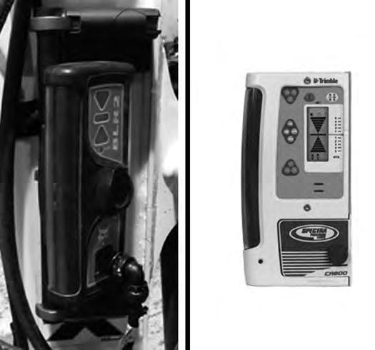
Measuring The Laser Location
Figure 233
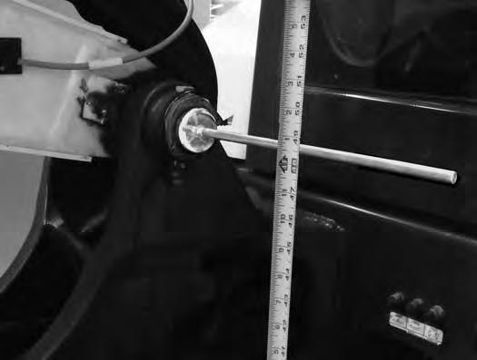
For the model BLR2 (Item 1), measure to the center of the knob (Item 2) [Figure 233]
For the model CR600 (Item 3), measure to the center of the red line (Item 4) [Figure 233]
DEPTH CHECK (CONT’D)
Initial Setup (Cont’d)
Preferences
The Preferences screen is used to set two features;
1. To set the screen preference for; Distance to Target, Depth Check or Grade Check.

2. To set units of measure (screen can be set to display; millimeters, meters, feet or inches).
Press [4. PREFERENCES] (Item 4) [Figure 234] to change to the Defaults screen [Figure 235]
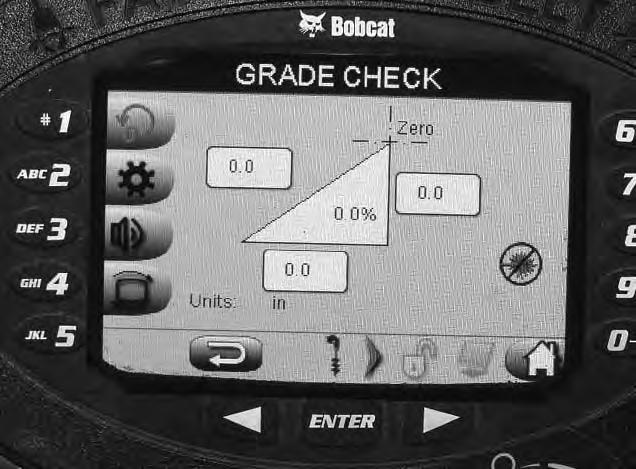
Press [DEFAULT SCREEN] button (Item 1) [Figure 235] to toggle the Preference screen between the following screens; Distance to Target [Figure 236], Depth Check [Figure 237] or Grade Check [Figure 238]
Press the [UNITS] button (Item 2) to toggle between meters, millimeters, feet or inches. This sets how you will record and enter ALL dimensions into the Depth Check system. The selected units will be displayed under the word [UNITS] (Item 3) [Figure 235] and will be visible on all Depth Check screens that show dimensions.


DEPTH CHECK (CONT’D)
Initial Setup (Cont’d)
Preferences (Cont’d)
Figure 238
Operation
The following will give some basic operation information for :
Warning
AVOID INJURY OR DEATH
Check area to be excavated for overhead or underground lines such as electrical, gas, oil, water, etc. CALL 1-888-258-0808 and consult local utilities before digging. Extreme caution must be used in areas where utility lines are present.
W-2116-0903
Grade Check [Figure 238] screen.

NOTE:You can also press button (Item 4) [Figure 236], [Figure 237] or [Figure 238] to toggle between these three screens any time that the icon (Item 4A) is visible on any Depth Check screen.
Important
When digging in an area with underground utilities, do not depend on the Depth Check system for digging close to known utilities. The Depth Check system accuracy is dependent on the accuracy of the calibration, slope of the ground and other unknown variables. The current depth of utility lines varies and may not be to the same depth as when the utility was buried due to soil erosion, grading and many other factors. Some laws require non-mechanical (hand) digging in the area of marked underground utilities. Make sure you follow all local rules and regulations regarding digging in the area of underground utilities.
I-2383-1214
DEPTH CHECK (CONT’D)
Operation (Cont’d)
Digging A Hole To A Predetermined Depth (Re-benching Without A Laser Reference)
Figure 239
The first step is to set the position of the bucket (Item 1) [Figure 239] at the ground surface you are going to start the dig or on the surveyor mark to establish the starting ground position. Lower the bucket until it is on the ground or on the surveyor mark. This is called re-benching.
Select the target depth by pressing button (Item 1 through Item 5) [Figure 241] for selecting an existing depth. (To add a new target depth or to change an existing target depth, see information shown with steps [Figure 218] through [Figure 223].)
The selected target depth will now appear on the screen at (Item 6A) [Figure 240].
NOTE:If the excavator is at an angle (side slope) when re-benching, the system will only be accurate on the same plane (location) that it was re-benched at.

To set the cutting edge position (re-benching) to zero, access the Depth Check screen, and press the rebenching button (Item 1). After the button is pressed, the dimensions on the screen for depth (Item 1A) will be set to 0.0. (As the bucket is raised or lowered, the screen at (Item 1A) [Figure 240] will show the bucket position dimension moving.)

Press button (Item 6) [Figure 240] to change to the [SELECT DEPTH TARGET] screen [Figure 241]

DEPTH CHECK (CONT’D)
Operation (Cont’d)
Digging A Hole To A Predetermined Depth (Re-benching Without A Laser Reference) (Cont’d)
As the hole is being dug, the position of the bucket (Item 1) [Figure 242] is dimensionally shown (Item 1A) [Figure 240] and shown on the bar graph at (Item 1B) [Figure 240]. The distance to target depth is dimensionally shown in (Item 2) [Figure 240] and shown on the bar graph (Item 2A) [Figure 240]
When the bucket is getting close to the target depth, a warning buzzer (if activated) will start to slowly beep. The beeps will increase in frequency the closer the bucket gets to the target depth. When the target depth is reached, the buzzer will sound continuously.
EXAMPLE: The target depth is 2 meters (6.5 ft) (Item 6A) and the position of the bucket (Item 1A) is at 1.5 meter (4.9 ft), the distance to target (Item 2) [Figure 240] will be 0.5 m (1.6 ft). [2 m - 1.5 m = 0.5 m (6.5 ft - 4.9 ft = 1.6 ft).]
NOTE:The distance from the target depth to when the when the alarm starts to beep can be set using the Warning Zone information. (See Warning Zone on Page 126.)
To reposition the excavator to continue digging the hole at the original depth;


If possible, reposition the excavator so the bucket can be re-benched off of the original starting point (Item 1) [Figure 243].
Or, If that is not possible, position the excavator so the bucket will reach to the bottom of the hole (Item 2) [Figure 243] at an area that is know to be the correct depth. (When re-benched at the bottom of the trench, set the target depth to zero to continue digging at the original depth.)
Or, With the bucket on the ground next to the excavator (Item 3) [Figure 243], re-bench the bucket to zero. Now reach into the existing hole until the bucket is touching the bottom of the hole (Item 2) [Figure 243] in an area you know is the correct depth. Example: The dimension shown in (Item 1A) [Figure 240] is now 2.5 m (8.2 ft). You now need to reset the target depth to 2.5 m (8.2 ft) to continue digging the hole at the original target depth.
Or, If you want to just continue digging with the hole parallel to the ground, no re-benching is necessary but the hole will not be horizontal, it will be at the same plane as the ground surface the machine is on.
DEPTH CHECK (CONT’D)
Operation (Cont’d)
Digging A Hole To A Predetermined Width And Depth (Re-benching Without A Laser)
EXAMPLE: Digging a 2.0 meter wide x 1.5 meter deep (6.5 ft wide x 3 ft deep) hole.
Follow the same procedure as for digging a hole except as follows. (See Digging A Hole To A Predetermined Depth (Re-benching Without A Laser Reference) on Page 130.)
When re-benching the bucket for setting to 0.0., position the bucket (Item 1) [Figure 244] at the starting point of the side of the hole that the excavator is positioned on.

This will allow the Depth Check to know the starting position of the hole for the depth and width of the hole.
The [ZERO] (Item A) is the re-benching starting point. (Item B) shows the target depth. (Item C) [Figure 245] shows the reach (distance away from the zero mark star ting point (Item 1) [Figure 244].
NOTE:The warning buzzer (if activated) will start to beep when getting close to the target depth and progressively beeps faster until the target depth is reach and then the buzzer will sound continuously. The buzzer only activates on the depth, not for the reach (width of hole). That will need to be monitored visually using (Item C) [Figure 245].
Warning
AVOID INJURY OR DEATH
Check area to be excavated for overhead or underground lines such as electrical, gas, oil, water, etc. CALL 1-888-258-0808 and consult local utilities before digging. Extreme caution must be used in areas where utility lines are present.
W-2116-0903
DEPTH CHECK (CONT’D)
Operation (Cont’d)
Digging A Hole Using A Laser
Read and understand the information supplied with the laser for correctly setting up the laser system.
NOTE: Make sure the laser receiver dimensional location on the arm has been added into the Depth Check. For additional information. (See Laser Receiver Position On Arm on Page 127.)
With the arm vertical, raise or lower the boom and arm as needed until the laser (Item 1) strikes the receiver (Item 2) [Figure 246]. (If needed, curl the bucket fully for increased bucket ground clearance or a hole may need to be dug so that the bucket can be lowered to allow the laser to strike the receiver with the arm vertical.)

NOTE:If the arm is not vertical and you try to rebench, a screen will tell you to make the arm vertical before it will allow the re-bench.
With the laser striking the receiver, press (Item 1) [Figure 247] to set the laser position.
Press (Item 6) to access the pre-set Target Depth screen or go to figure [Figure 219] to add or change the target depth. When the correct target depth is entered, press the [ENTER] button (Item C) [Figure 247] to save the setting.
With the Depth Check system set-up, the excavator can now be repositioned anywhere in the laser range and the dig depth will stay consistent to the set target depth.
DEPTH CHECK (CONT’D)
Operation (Cont’d)
Digging A Trench With Slope Using A Laser (Re-benching Using A Laser Reference)
Read and understand the information supplied with the laser for correctly setting up the laser system.
NOTE:Digging a slope with a laser requires a laser that has slope capability. The laser must be positioned square with the desired direction of the slope.
NOTE:Make sure the laser receiver dimensional location on the arm has been added into the Depth Check. For additional information. (See Laser Receiver Position On Arm on Page 127.)
With the arm vertical, raise or lower the boom and arm as needed until the laser (Item 1) strikes the receiver (Item 2) [Figure 248]. (If needed, curl the bucket fully for increased bucket ground clearance or a hole may need to be dug so that the bucket can be lowered to allow the laser to strike the receiver with the arm vertical.)
NOTE:If the arm is not vertical and you try to rebench, a screen will tell you to make the arm vertical before it will allow the re-bench.
With the laser striking the receiver, press (Item 1) [Figure 249] to set the laser position.
Press (Item 6) to access the pre-set target depth screen or go to figure [Figure 219] to add or change the target depth. When the correct target depth is entered, press the [ENTER] button (Item C) [Figure 249] to save the setting.
With the Depth Check system set-up, the excavator can now be repositioned anywhere in the laser range and the dig depth will stay consistent to the set target depth and to the slope set with the laser.