20 minute read
MONITORING THE DISPLAY PANELS


Instrument Panel
Figure 93
Frequently monitor the temperature and fuel gauges [Figure 93]
After the engine is running, frequently monitor the instrument panel [Figure 93] for machine condition.

The associated icon is displayed if there is an error condition.
EXAMPLE: Engine Coolant Temperature is High.
The Engine Coolant Temperature icon (Item 1) [Figure 93] is ON.
Press the Information button (Item 2) (Standard Panel) or press a scroll button (Item 3) [Figure 93] (Deluxe Panel) repeatedly to cycle the data display until the service code screen is displayed. One of the following SERVICE CODES is displayed.
• [M0810] Engine Coolant Temperature Too High
• [M0811] Engine Coolant Temperature Extremely High
Find the cause of the service code and correct before operating the excavator again. (See DIAGNOSTIC SERVICE CODES on Page 193.)
NOTE:The optional Deluxe Instrumentation Panel offers an additional view of service codes that includes a brief description. (See DIAGNOSTIC SERVICE CODES on Page 193.)
Warning And Shutdown
When a WARNING condition exists; the associated icon light is ON and the alarm sounds 3 beeps. If this condition is allowed to continue, there may be damage to the engine or hydraulic systems.
When a SHUTDOWN condition exists; the associated icon light is ON and the alarm sounds continuously. The monitoring system will automatically stop the engine in 15 seconds. The engine can be restarted to move or relocate the excavator.
The SHUTDOWN feature is associated with the following icons:
General Warning
Engine Malfunction
Engine Coolant Temperature
Hydraulic Fluid Temperature
STOPPING THE ENGINE AND LEAVING THE EXCAVATOR

Procedure
94
Stop the machine on level ground. Lower the work equipment and the blade to the ground [Figure 94]
Turn the switch to STOP [Figure 96]
Disconnect the seat belt. Remove the key from the switch (If Equipped) to prevent operation of machine by unauthorised personnel. Raise the control console and exit the machine.

Rotate the engine speed control dial (Item 1) [Figure 95] anticlockwise to low idle.
Run the engine at idle speed for about 5 minutes to allow it to cool.

Attachments
Installing And Removing The Attachment (Quick Coupler, Lehnhoff® System)
Installation
NOTE: Installation and removal of the bucket is shown. The procedure is the same for other attachments. Disconnect any hydraulic lines that are operated by hydraulic power before removing any attachments (breaker, auger etc.).
Warning
AVOID INJURY OR DEATH
Never use attachments or buckets which are not approved by Bobcat Company. Buckets and attachments for safe loads of specified densities are approved for each model. Unapproved attachments can cause injury or death.
W-2052-0907
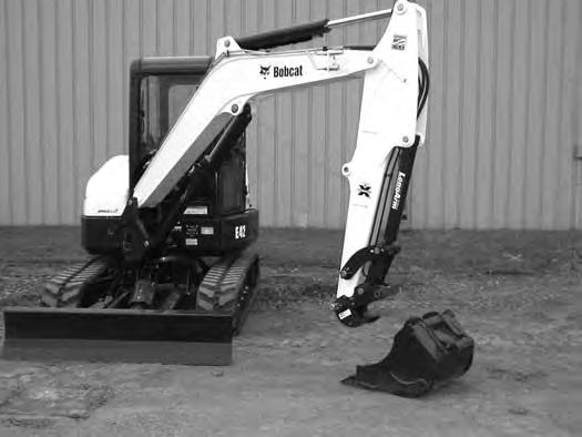
Position the excavator so the excavator arm is above the attachment.
Fully retract the bucket cylinder.
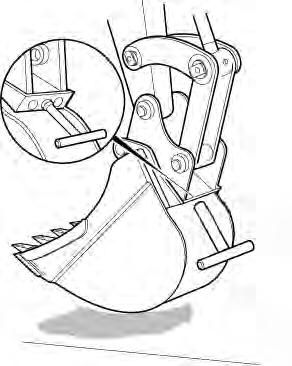
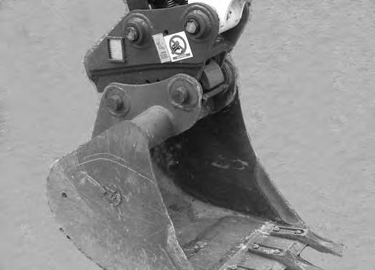
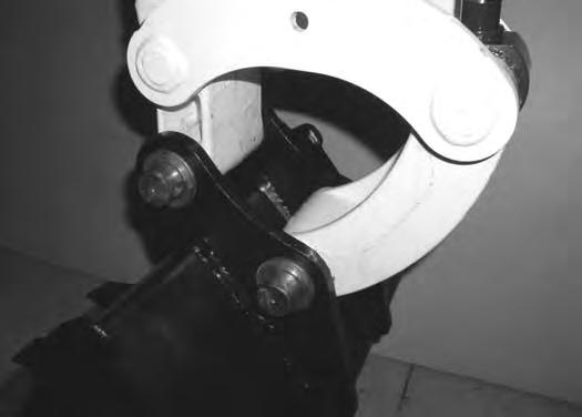
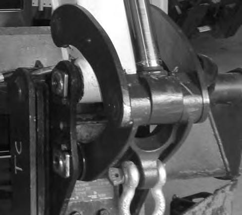
Lower the coupler (Item 1) onto the attachment (Item 2) [Figure 97]
Engage the coupler hooks (Item 1) onto the attachment shaft (Item 2) [Figure 98]
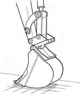
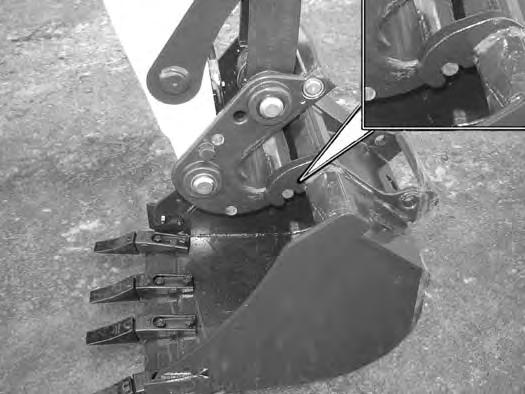
Extend (curl in) the bucket cylinder and slightly raise the boom until the coupler (Item 1) contacts the back of the attachment mount (Item 2) [Figure 99]
ATTACHMENTS (CONT’D)
Installing And Removing The Attachment (Quick Coupler, Lehnhoff® System) (Cont’d)
Installation (Cont’d)
Engage the parking brake.
Stop the engine and exit the excavator.
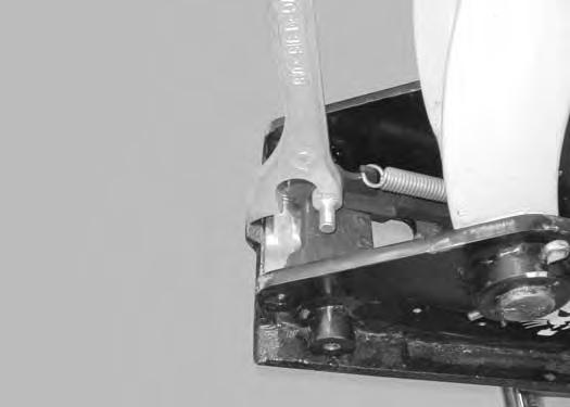
Use the supplied wrench (Item 1) [Figure 100] and turn the locking pins clockwise until they are fully engaged.
Removal
Park the excavator on a level surface.
S3019A S3020A
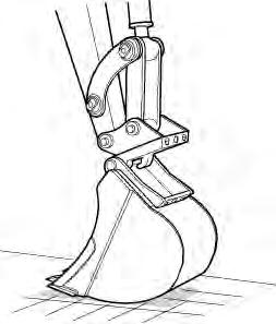
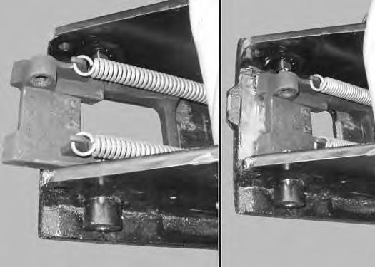
Install the wrench (Item 1) [Figure 102] on the locking pins and turn anticlockwise until the locking pins are disengaged.

S3017A
Raise the boom and extend the bucket cylinder until the attachment it is slightly off the ground [Figure 101]
Engage the parking brake.
Stop the engine and exit the excavator.
Enter the excavator, fasten the seat belt and start the engine
ATTACHMENTS (CONT’D)
Installing And Removing The Attachment (Quick Coupler, Lehnhoff® System) (Cont’d)
Removal (Cont’d)
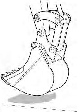
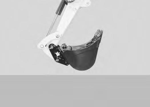
Retract the bucket cylinder to rotate the coupler (Item 1) out of the attachment mount (Item 2) [Figure 104]
Quick Coupler And Attachment Inspection
Inspect the quick coupler for wear or damage. Inspect the attachment shaft and the quick coupler hooks for wear or damage.
Repair or replace damaged parts.
Move the arm out and raise the boom until the quick coupler is clear of the attachment [Figure 105]
ATTACHMENTS (CONT’D)

Installing And Removing The Attachment (Quick Coupler, Klac™ System)
Installation
NOTE: Installation and removal of the bucket is shown. The procedure is the same for other attachments. Disconnect any hydraulic lines that are operated by hydraulic power before removing any attachments (breaker, auger etc.).
Warning
AVOID INJURY OR DEATH
Never use attachments or buckets which are not approved by Bobcat Company. Buckets and attachments for safe loads of specified densities are approved for each model. Unapproved attachments can cause injury or death.
W-2052-0907
Warning
AVOID INJURY
Keep fingers and hands out of pinch points when latching and unlatching the attachment quick coupler.
W-2541-1106
Fully retract the bucket cylinder.
Stop the engine and exit the excavator.
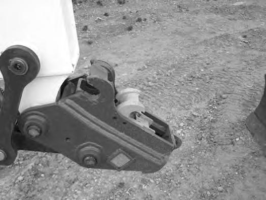
Inspect the quick coupler to make sure the latch is in the unlatched position (Item 1) [Figure 106]
If in the latched position, see [Figure 107] for additional information.
If the latch is in the unlatched position, proceed to [Figure 108].
To unlatch the quick coupler, install the tool (Item 1) [Figure 107] and pull the handle. The latch will move completely forward. The latch will lock in the unlatched position.
Enter the excavator, fasten the seat belt and start the engine.
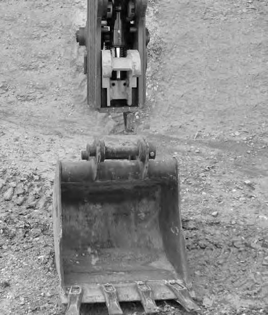
Position the quick coupler (Item 1) to the attachment (Item 2) [Figure 108]
ATTACHMENTS (CONT’D)

Installing And Removing The Attachment (Quick Coupler, Klac™ System) (Cont’d)
Installation (Cont’d)
There must be at least 100 between the quick coupler surface (Item 1) and the attachment mounting surface (Item 2) [Figure 109]. Extend the arm out to get the required angle for proper installation.

NOTE: There must be proper clearance (100 minimum) between the hook (Item 3) and the quick coupler (Item 4) [Figure 109]. Possible damage to the attachment hooks or the quick coupler could occur without proper clearance.

Raise the boom until there is approximately 500 mm (20.0 in) of clearance between the bottom of the attachment and the ground [Figure 111]
Raise the boom and extend the arm until the hooks of the attachment (Item 1) engage the pins (Item 2) of the quick coupler [Figure 110]
Extend the bucket cylinder (Item 1) [Figure 112] fully.
Lower the attachment until it is flat on the ground.
Stop the engine and exit the excavator.
ATTACHMENTS (CONT’D)
Installing And Removing The Attachment (Quick Coupler, Klac™ System) (Cont’d)
Installation (Cont’d)
Visually inspect the quick coupler latch (Item 1) to the bucket mount (Item 2) [Figure 113]. The latch must be fully engaged.
Warning
AVOID INJURY
Keep fingers and hands out of pinch points when latching and unlatching the attachment quick coupler.
W-2541-1106
If the latch is not engaged, install the tool (Item 1) in the hole (Item 2) [Figure 114] of the quick coupler and push down to unlatch the quick coupler. Remove the tool. Enter the excavator, fasten the seat belt and start the engine. Raise the attachment 500 mm (20.0 in) off of the ground and fully extend the bucket cylinder. Lower the attachment until it is flat on the ground. Stop the engine and exit the excavator.
Again, visually inspect the quick coupler to make sure the latch (Item 1) [Figure 113] is fully engaged. If it is not fully engaged, remove the attachment and inspect both the quick coupler and the attachment for damage or debris. (See Inspection And Maintenance on Page 184.)


ATTACHMENTS (CONT’D)
Installing And Removing The Attachment (Quick Coupler, Klac™ System) (Cont’d) Removal
Warning
AVOID INJURY
Keep fingers and hands out of pinch points when latching and unlatching the attachment quick coupler.
W-2541-1106
Position the attachment flat on the ground.
Install the quick coupler tool (Item 1) into the hole (Item 2) [Figure 114] in the quick coupler.
Push down on the tool (Item 1) [Figure 115] to unlock the latch.
Remove the tool.
Enter the excavator, fasten the seat belt and start the engine.
Retract the bucket cylinder fully and lower the boom [Figure 116] until the attachment is on the ground.
Continue to lower the boom and move the arm towards the excavator until the quick coupler is clear of the attachment [Figure 117]


ATTACHMENTS (CONT’D)
Installing And Removing The Attachment (Hydraulic X-Change)
Installation
NOTE: Installation and removal of the bucket is shown. The procedure is the same for other attachments. Disconnect any hydraulic lines that are operated by hydraulic power before removing any attachments (breaker, auger, etc.).
Warning
AVOID INJURY OR DEATH
Never use attachments or buckets which are not approved by Bobcat Company. Buckets and attachments for safe loads of specified densities are approved for each model. Unapproved attachments can cause injury or death.
W-2052-0907
Warning
AVOID INJURY OR DEATH
Both hydraulic pins must be fully extended through the attachment mounting holes. Failure to fully engage the hydraulic pins can allow attachment to come off.
W-2935-0512
Figure 119
Start the engine.
Swing the excavator arm fully to the left [Figure 118] (for better operator visibility when connecting attachments).


Press and hold the X-Change switch (Item 1) [Figure 119] to the right (IN) to fully retract the hydraulic pins.
Move the arm toward the attachment [Figure 120]
Raise the boom until the X-Change pins (Item 1) engage the attachment hooks (Item 2) [Figure 121] on the bucket.
ATTACHMENTS (CONT’D)
Installing And Removing The Attachment (Hydraulic X-Change) (Cont’d)

Installation (Cont’d)
Figure 122
123
Raise the boom and extend (curl in) the bucket cylinder until the X-Change contacts the back of the attachment [Figure 122]
With the arm vertical, lower the boom until the hooks (Item 1) of the bucket disengage the X-Change pins (Item 2) and the plate (Item 3) [Figure 122] fully engages into the bucket crossmember.

Warning
Keep all bystanders 6 m (20 ft) away from equipment when operating. Contact with moving parts, a trench cave-in or flying objects can cause injury or death.
W-2119-0910
Press and hold the X-Change switch (Item 1) [Figure 123] to the left (OUT) and FULLY EXTEND the hydraulic pins.
124
Check that both hydraulic pins (Item 1) [Figure 124] are fully engaged to secure the attachment.
Warning
AVOID INJURY OR DEATH
Both hydraulic pins must be fully extended through the attachment mounting holes. Failure to fully engage the hydraulic pins can allow attachment to come off.
W-2935-0512
ATTACHMENTS (CONT’D)
Installing And Removing The Attachment (Hydraulic X-Change) (Cont’d)

Removal
NOTE: Removal and installation of the bucket is shown. The procedure is the same for other attachments. Disconnect any hydraulic lines that are operated by hydraulic power before removing any attachments (breaker, auger, etc.).
Warning
Keep all bystanders 6 m (20 ft) away from equipment when operating. Contact with moving parts, a trench cave-in or flying objects can cause injury or death.
W-2119-0910
Raise the boom and retract the bucket cylinder until the X-Change pins (Item 1) engage the attachment hooks (Item 2) [Figure 127] on the bucket.
Park the excavator on a flat level surface. Put the attachment on the ground [Figure 125]

Fully retract the bucket cylinder (bucket dump).
Lower the boom and arm until the attachment is on the ground and the X-Change pins are disengaged from the attachment hooks.
Move the arm toward the excavator until the X-Change pins are clear of the attachment [Figure 128]
Press and hold the X-Change switch (Item 1) [Figure 126] on the left console to the right (IN) to FULLY RETRACT the hydraulic pins.
ATTACHMENTS (CONT’D)
Installing And Removing The Attachment (Pin Grabber Quick Coupler)
Installation
NOTE: Installation and removal of the bucket is shown. The procedure is the same for other attachments. Disconnect any hydraulic lines that are operated by hydraulic power before removing any attachments (breaker, auger, etc.).
Warning
AVOID INJURY OR DEATH
Never use attachments or buckets which are not approved by Bobcat Company. Buckets and attachments for safe loads of specified densities are approved for each model. Unapproved attachments can cause injury or death.
W-2052-0907
Start the engine. (See PRE-STARTING PROCEDURE on Page 67.)

Warning
AVOID INJURY OR DEATH
The quick coupler locking clasps must be fully engaged and locked to the attachment pins. Failure to fully engage the locking clasps can allow attachment to come off.

ATTACHMENTS (CONT’D)
Installing And Removing The Attachment (Pin Grabber Quick Coupler) (Cont’d)
Installation (Cont’d)
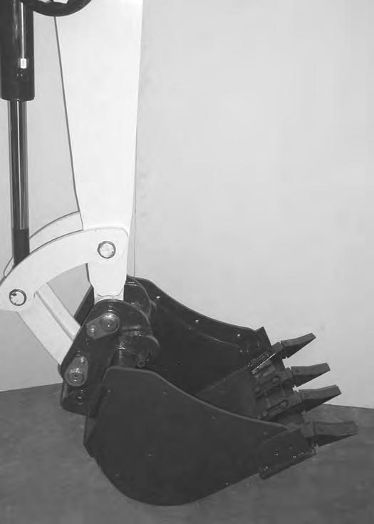
Press the coupler ON / OFF switch (Item 1) [Figure 132] to the left (ON) position to enable the pin grabber quick coupler feature. The switch will illuminate when in the ON position and a buzzer will sound.
Press and release the INTENT switch (Item 2) within five seconds (The buzzer will continue to sound and the light (Item 1) [Figure 132] will stay ON.)
Roll the coupler out. Move the arm toward the attachment. Reposition the boom, arm and coupler until the coupler (Item 1) [Figure 134] is position over the attachment pin. Raise the attachment up slightly.

Continue to curl the quick coupler until the locking clasp (Item 1) [Figure 133] moves in fully.
Curl the quick coupler in fully [Figure 135]
Press the coupler ON / OFF switch (Item 1) [Figure 132] to the right, (OFF) position. The switch light and buzzer will tur n OFF.

Continue to curl the attachment in for an additional ten seconds to allow the locking clasp to move and lock to the attachment pins.
With the attachment as low to the ground as possible, curl the attachment out and in several times to ensure the attachment is secured to the coupler.
Lower the attachment flat to the ground.
ATTACHMENTS (CONT’D)
Installing And Removing The Attachment (Pin Grabber Quick Coupler) (Cont’d)
Installation (Cont’d)
Figure 136
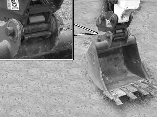
Visually check that the green locking clasp (Item 1) [Figure 136] is FULLY ENGAGED AND LOCKED
Warning
Keep all bystanders 6 m (20 ft) away from equipment when operating. Contact with moving parts, a trench cave-in or flying objects can cause injury or death.
W-2119-0910
Warning
AVOID INJURY OR DEATH
The quick coupler locking clasps must be fully engaged and locked to the attachment pins. Failure to fully engage the locking clasps can allow attachment to come off.
W-2978-0813
ATTACHMENTS (CONT’D)
Installing And Removing The Attachment (Pin Grabber Quick Coupler) (Cont’d)
Removal
NOTE: Removal and installation of the bucket is shown. The procedure is the same for other attachments. Disconnect any hydraulic lines that are operated by hydraulic power before removing any attachments (breaker, auger, etc.).

Warning
Keep all bystanders 6 m (20 ft) away from equipment when operating. Contact with moving parts, a trench cave-in or flying objects can cause injury or death.
W-2119-0910
Press the coupler ON / OFF switch (Item 1) [Figure 139] to the left (ON) position to enable the pin grabber quick coupler feature. The switch will illuminate when in the ON position and a buzzer will sound.
Press and release the INTENT switch (Item 2) within five seconds. (The buzzer will continue to sound and the light (Item 1) [Figure 139] will stay ON.)
Move the right joystick (Item 1) [Figure 137] to the left (IN) and continue to curl the quick coupler [Figure 138] The coupler locking clasps will lift fully to unlock the attachment from the quick coupler.
Move
With the attachment slightly off of the ground, roll the quick coupler back until the coupler starts to disengage from the attachment [Figure 140]
ATTACHMENTS (CONT’D)
Installing And Removing The Attachment (Pin Grabber Quick Coupler) (Cont’d)
Removal (Cont’d)
Roll the quick coupler back fully.
Lower the boom and arm until the attachment is on the ground and the quick coupler is disengaged from the attachment pins.
Move the arm away the excavator until the quick coupler is clear of the attachment [Figure 141]

ATTACHMENTS (CONT’D)
Installing And Removing The Attachment (Pin-On X-Change)

Installation
NOTE: Installation and removal of the bucket is shown. The procedure is the same for other attachments. Disconnect any hydraulic lines that are operated by hydraulic power before removing any attachments (breaker, auger, etc.).
Warning
AVOID INJURY OR DEATH
Never use attachments or buckets which are not approved by Bobcat Company. Buckets and attachments for safe loads of specified densities are approved for each model. Unapproved attachments can cause injury or death.
W-2052-0907
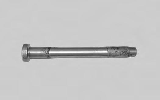
Inspect the pin (Item 1) [Figure 143] for wear or damage. Replace the pin as needed.
Apply a light coat of grease to the ends of the pin (Item 2) [Figure 143]
ATTACHMENTS (CONT’D)
Installing And Removing The Attachment (Pin-On X-Change) (Cont’d)
Installation (Cont’d)
Raise the boom until the pins (Item 1) engage the hooks (Item 2) [Figure 145] on the bucket.
Raise the boom and extend the bucket cylinder until the X-Change contacts the attachment back [Figure 146]
With the arm vertical, lower the boom until the hooks (Item 1) of the bucket disengage the pins (Item 2) of the X-Change and the plate (Item 3) [Figure 146] fully engages in the bucket crossmember.

Warning
Keep all bystanders 6 m (20 ft) away from equipment when operating. Contact with moving parts, a trench cave-in or flying objects can cause injury or death.
W-2119-0910
ATTACHMENTS (CONT’D)
Installing And Removing The Attachment (Pin-On X-Change) (Cont’d)
Installation (Cont’d)
Stop the engine. Turn the start key to the ON position and move both hydraulic control levers to relieve hydraulic pressure.

Drive the pin (Item 1) [Figure 147] through the bucket mount
Install the retainer pin (Item 1) [Figure 148]
Check for proper installation.
Lift the attachment and fully extend and retract the bucket cylinder
ATTACHMENTS (CONT’D)
Installing And Removing The Attachment (Pin-On X-Change) (Cont’d)

Removal
NOTE: Removal and installation of the bucket is shown. The procedure is the same for other attachments. Disconnect any hydraulic lines that are operated by hydraulic power before removing any attachments (breaker, auger, etc.).
Warning
AVOID INJURY OR DEATH
Never use attachments or buckets which are not approved by Bobcat Company. Buckets and attachments for safe loads of specified densities are approved for each model. Unapproved attachments can cause injury or death.
W-2052-0907
With the engine off, turn the start key to the ON position and move both hydraulic control levers to relieve hydraulic pressure.
ATTACHMENTS (CONT’D)
Installing And Removing The Attachment (Pin-On X-Change) (Cont’d)

Removal (Cont’d)
Warning
AVOID INJURY OR DEATH
Wear safety glasses to prevent eye injury when any of the following conditions exist:
•When fluids are under pressure.
•Flying debris or loose material is present.
•Engine is running.
•Tools are being used.
Start the engine, raise the boom approximately one foot and retract the bucket cylinder until the X-Change pins (Item 1) engage the hooks (Item 2) [Figure 152] on the bucket.
ATTACHMENTS (CONT’D)
Installing And Removing The Attachment (Pin-On X-Change) (Cont’d)
Removal (Cont’d)
ATTACHMENTS (CONT’D)
Installing And Removing The Attachment (Pin-On Attachment)
Installation
Warning
AVOID INJURY OR DEATH
Stop the machine on a firm flat surface. When removing or installing attachments (such as a bucket), always have a second person in the operator’s seat, give clear signals and work carefully.
W-2140-0189
Install the two retainer pins (Item 1) [Figure 155]. Install grease in the grease fittings.
Removal
Park the excavator on a flat surface and lower the bucket fully
Remove the two retainer pins (Item 1) [Figure 155]
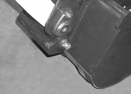
Remove the washers and pins (Items 1 and 3) [Figure 154]
Install the arm into the bucket and align the mounting hole.
Install the pin (Item 1) [Figure 154] and washers.
Install the link (Item 2) in the bucket and align the mounting hole. Install the pin (Item 3) [Figure 154] and washers.

Do not damage the dust seals in the arm.
Warning
AVOID INJURY OR DEATH
Never use attachments or buckets which are not approved by Bobcat Company. Buckets and attachments for safe loads of specified densities are approved for each model. Unapproved attachments can cause injury or death.
W-2052-0907
OPERATING PROCEDURE Inspect The Work Area
Before beginning operation, inspect the work area for unsafe conditions.
Look for sharp drop-offs or rough terrain. Have underground utility lines (gas, electrical, water, sewer, irrigation, etc.) located and marked. Work slowly in areas of underground utilities.
Remove objects or other construction material that could damage the excavator or cause personal injury.
Always check ground conditions before starting your work:
•Look for signs of instability such as cracks or settlement.
•Be aware of weather conditions that can affect ground stability.
•Check for adequate traction if working on a slope.
Basic Operating Instructions
When operating on a public road or motorway, always follow local regulations. For example: A slow moving vehicle (SMV) sign, or direction signals may be required.
Run the engine at low idle speed to warm the engine and hydraulic system before operating the excavator.
Important
Machines warmed up with moderate engine speed and light load have longer life.
I-2015-0284
New operators must operate the excavator in an open area without bystanders. Operate the controls until the excavator can be handled at an efficient and safe rate for all conditions of the work area.
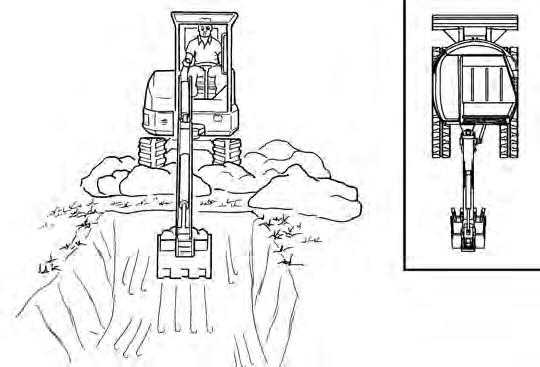
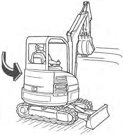
Operating Near An Edge Or Water
Keep the excavator as far back from the edge as possible and the excavator tracks perpendicular to the edge so that if part of the edge collapses, the excavator can be moved back.
Always move the excavator back at any indication the edge may be unstable.
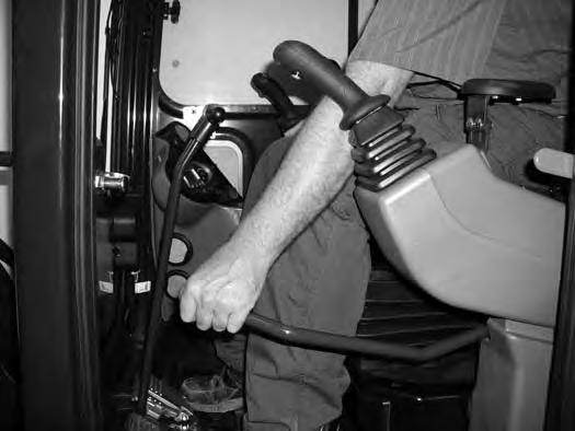
Lowering The Work Equipment (Engine STOPPED)
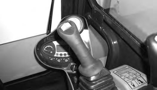
The hydraulic control levers control the movement of the boom, arm, bucket and upperstructure slew functions.
The console must be in the locked down position, and the key switch in the ON position.
Use the control lever to lower the boom.
Figure 156
The joystick lock switch disengages the hydraulic control functions from the joysticks when the console are raised [Figure 156]
NOTE: If the engine stops, the boom / bucket (attachments) can be lowered to the ground using hydraulic pressure in the accumulator.
The control console must be in the locked down position, and the key switch in the ON position.
Use the control lever to lower the boom. Lower the control console to engage the hydraulic control functions of the joysticks [Figure 156]
OPERATING PROCEDURE (CONT’D)
Object Handling With The Lifting Device
The excavator must be equipped with the optional lift eye link (Item 1) [Figure 158], the boom and arm load hold valves and the overload warning device option. See your Bobcat dealer for available Kits.
Warning
AVOID INJURY OR DEATH
•Do not exceed rated lift capacity.
•Excessive load can cause tipping or loss of control.
•Excessive load can cause failure of the lift eye and cause the load to drop.
W-2991-0714
Do not exceed the machine’s Rated Lift Capacity or the Rated Lift Load (RLL) of the lifting device (lift eye). (See Rated Lift Capacity (Standard Arm) on Page 214.) or (See Rated Lift Capacity (Long Arm) on Page 215.)
Make sure the secondary lifting system (chain) is of sufficient strength to lift the object.

NOTE: Visually check the lifting eye, the clevis and the secondary lifting system (chain) for any damage. Replace any damage components before lifting. See your Bobcat dealer for replacement lift eye and clevis.
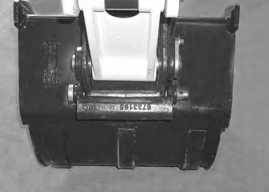
The maximum RLL (Item 1) [Figure 157] is shown on the lifting device.
Extend the bucket cylinder completely and lower the boom to the ground. Stop the engine. Exit the excavator. (See STOPPING THE ENGINE AND LEAVING THE EXCAVATOR on Page 75.)
OPERATING PROCEDURE (CONT’D)
Object Handling With The Lifting Device

Figure 159
Install a lift chain (Item 1) (or other type of lifting device) through the clevis (Item 2) [Figure 159] and connect to the object to be lifted.
NOTE:Always use chains or other types of lifting devices that are intended for this type of use and that are of adequate strength for the object being lifted.

Enter the excavator, fasten the seat belt and start the engine. (See PRE-STARTING PROCEDURE on Page 67.)
Make sure the load is evenly weighted and centered on the lifting chain (or other type of lifting device), and is secured to prevent the load from shifting [Figure 161]
Operate the controls slowly and smoothly to avoid suddenly swinging the lifted load.
Lift and position the load. When the load is placed in a secured position and tension is removed from the lift chain, remove the chain from the load and from the lift eye.
Press the switch (Item 1) [Figure 160] to the left to activate the overload warning device.

OPERATING PROCEDURE (CONT’D)
Lift Capacity
The lifting capacities were calculated with a machine that was equipped with a standard bucket and the pin-on Xchange. The difference between the weight of the attachment and the standard bucket, the pin-on Xchange and the quick coupler (if equipped), and the hydraulic clamp (if equipped) must be subtracted.
AVOID INJURY OR DEATH
Do not exceed rated lift capacity. Excessive load can cause tipping or loss of control.
W-2374-0500
EXAMPLE OF LIFT CAPACITY CHART
* 1246 kg (2746 lb)
7188434
The following example will show how to calculate the lift capacity differences between the lift capacity charts with standard equipment and when using optional equipment.
The standard equipment weights used when determining lift capacity are as follows:

Standard Bucket = 142 kg (313 lb)
Pin-On X-Change = 28 kg (62 lb)
The following lists the weight of the optional quick couplers and hydraulic clamp:
•Pin-on X-Change = 28 kg (62 lb)
•Hydraulic X-Change = 40 kg (87 lb)
•Pin Grabber Quick Coupler = 65 kg (143 lb)
•Lehnhoff Quick Coupler = 30 kg (66 lb)
•Klac Quick Coupler = 43 kg (95 lb)
•TAG Quick Coupler = 26 kg (58 lb)
•Hydraulic Clamp And Cylinder = 86 kg (190 lb)
•Optional Buckets and Attachments (See NOTE below)
NOTE:For bucket weights, see your Bobcat dealer. For attachment weights, see the attachment Operation & Maintenance Manual.
OPERATING PROCEDURE (CONT’D)
Lift Capacity (Cont’d)
The following is an example for determining the lift capacity using the sample chart shown above [Figure 162]
- Machine Position: Over Blade, Blade Down
- Lift Radius: 4000 mm (125.5 in)
- Lift Point Height: 2000 mm (78.7 in)
- Hydraulic X-Change
- Hydraulic Clamp and Cylinder
- Standard Bucket
1. Obtain Lift Capacity from Chart: 1246 kg (2746 lb)
2. Subtract the difference between the weight of the standard configuration (Pin-On X-change and Standard Bucket) and optional equipment which in this case is the Hydraulic X-Change and the Hydraulic Clamp.
Quick Coupler (Pin-On X-Change minus Hydraulic X-change): 28 kg (62 lb) - 40 kg (87 lb) = minus 12 kg (25 lb)
Hydraulic Clamp and Cylinder: 86 kg (190 lb)
3. Calculate actual Lift Capacity for machine as configured: 1246 kg (2746 lb) - 12 kg (25 lb) (coupler difference) - 86 kg (190 lb) (hydraulic clamp and cylinder) = 1148 kg (2531 lb)
* The lift capacity charts (decals) are based off of ISO 10567: 2007. The lifting capacities are defined as the lower value of 75% of tipping load or 87% of the hydraulic lift capacity.
OPERATING PROCEDURE (CONT’D)
Using The Clamp (If Equipped)
Figure 163
The optional lifting clamp attachment gives the excavator a wider range of use and mobility for debris removal [Figure 163]
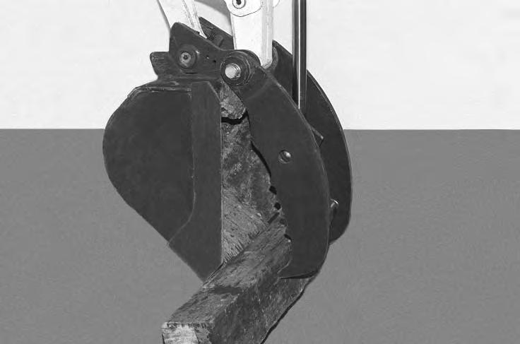
The lifting clamp cylinder must be fully retracted when the machine is being used for excavating.
The lift capacities are reduced by 86 kg (190 lb) if the excavator is equipped with the optional lifting clamp.
NOTE:Use care when operating the bucket and clamp functions on machines equipped with an X-Change and without a bucket or attachment installed. Cylinder damage can occur due to contact between the X-Change and the clamp when both cylinders are fully extended.
When Using Primary Auxiliary Hydraulics To Activate Clamp
Engage the auxiliary hydraulics and toggle to the Aux2 setting. (See Auxiliary Hydraulics - Standard Instrument Panel on Page 55.)
Figure 164
LEFT HAND CONTROL LEVER (JOYSTICK)
SECONDARY AUXILIARY HYDRAULICS
RIGHT HAND CONTROL LEVER (JOYSTICK)
PRIMARY AUXILIARY HYDRAULICS
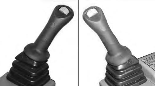
Move the switch (Item 1) [Figure 164] on the right control lever to the right to open the clamp. Move the switch to the left to close the clamp.
When Using Secondary Auxiliar y Hydraulics To Activate Clamp
Move the switch (Item 2) [Figure 164] on the left control lever to the left open the clamp. Move the switch to the right to close the clamp.
OPERATING PROCEDURE (CONT’D)
Excavating
Lower the blade to increase digging performance.
Figure 165
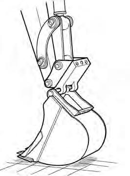
Extend the arm, lower the boom, and open the bucket [Figure 165]
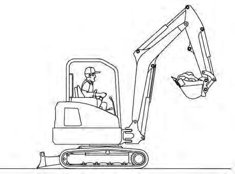
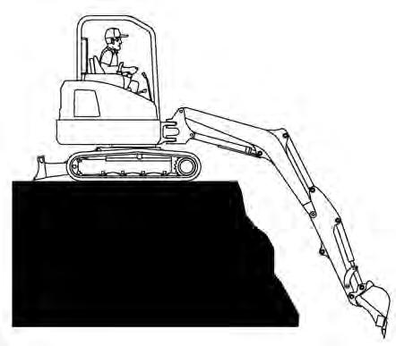

Figure 166
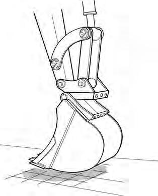
Retract the arm, while lowering boom and curling the bucket [Figure 166]
Raise the boom, retract the arm and curl the bucket [Figure 167]
Rotate the upperstructure.
NOTE:Do not allow the bucket teeth to contact the ground when swinging the upperstructure.
Warning
Keep all bystanders 6 m (20 ft) away from equipment when operating. Contact with moving parts, a trench cave-in or flying objects can cause injury or death.
W-2119-0910
Warning
AVOID
Injury Or Death
Check area to be excavated for overhead or underground electrical power lines. Keep a safe distance from electrical power lines.
W-2757-EN-0513
OPERATING PROCEDURE (CONT’D)
Excavating (Cont’d)
Look in the direction of rotation and make sure there are no bystanders in the work area before rotating the upperstructure [Figure 168]
Do not dig under the excavator [Figure 170]

Do not use the bucket as a breaker or pile driver. It is better to excavate hard or rocky ground after breaking it with other equipment. This will reduce damage to the excavator.
Do not move the excavator while the bucket is in the ground.
Dig only by moving the boom and arm toward the excavator.
Do not back dig (digging by moving the boom and arm away from the excavator). Damage to the X-Change and attachments may occur.

[Figure 169]
Avoid operating hydraulics over relief pressure. Failure to do so will overheat hydraulic components. I-2220-0503
OPERATING PROCEDURE (CONT’D)
Boom Swing
171
Slew the upperstructure, swing the boom to the right [Figure 171], centre [Figure 172] and left [Figure 173] to dig a square hole the width of the machine without repositioning the excavator.

The boom swing allows the operator to offset the boom and dig close to buildings and other structures [Figure 174].