18 minute read
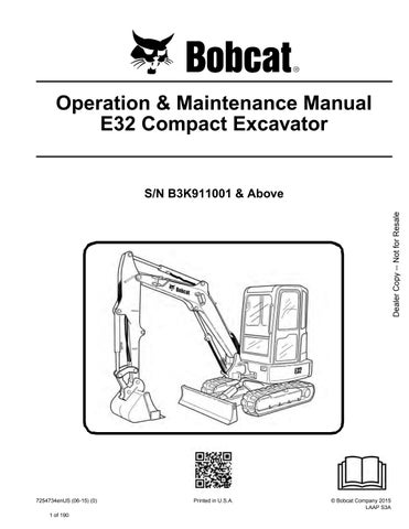
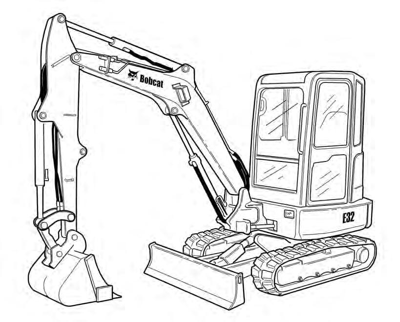
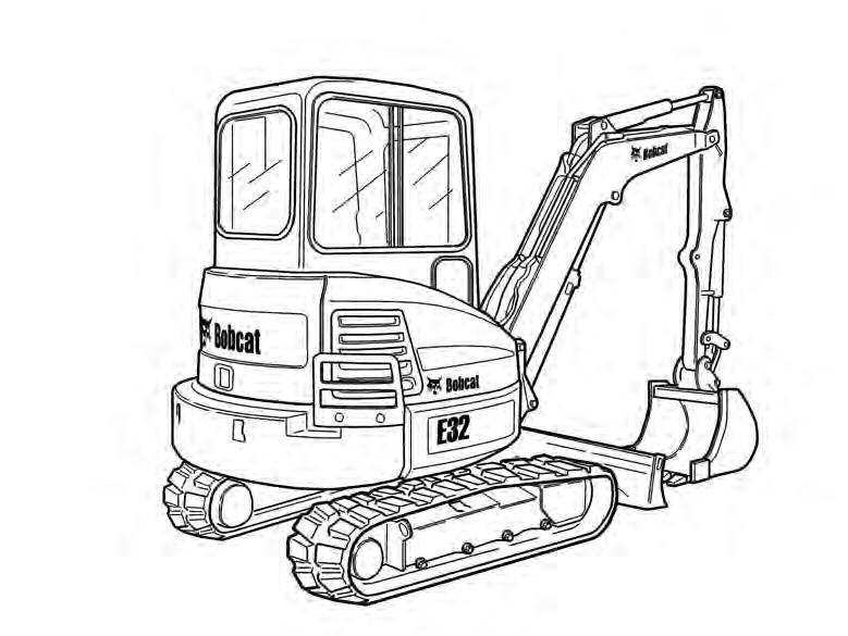
EXCAVATOR IDENTIFICATION


[1] BUCKET - Several different buckets and other attachments are available for the Bobcat excavator.

[2] ROPS / TOPS - (Roll-Over Protective Structure / Tip-Over Protective Structure) as standard equipment. The ROPS / TOPS meets ISO 12117-2:2008, ISO 12117: 2000 and EN13531:2001.
[3] TRACKS - Optional tracks are available.
FEATURES, ACCESSORIES AND ATTACHMENTS
Standard Items
Model E32 Bobcat excavators are equipped with the following standard items:
•1520 mm (59.8 in) Dozer Blade
•Canopy with ROPS / TOPS Approval
•320 mm (12.6 in) Rubber Tracks
•Two-Speed Travel
•Auto Shift Drive Motors
•Auxiliary Hydraulics (With Selectable Auxiliary Hydraulic Flow)
•Hydraulic and Travel Control Lockouts
•Engine Speed Control Dial With Auto Idle Feature
•Blade Float
•Work Lights - Boom and Frame Mounted
•Engine and Hydraulic system Monitor with Shut Down
•Horn
•Hydraulic Joystick Controls
•Suspension Seat
•Retractable Seat Belt
•Advanced Diagnostics
•Counterweight
Options And Accessories
Below is a list of some equipment available from your Bobcat excavator dealer as Dealer and/or Factory Installed Accessories and Factory Installed Options. See your Bobcat dealer for other available options, accessories and attachments.
•Enclosed Cab With Heater and A/C
•Enclosed Cab With Heater
•Deluxe Instrument Panel
•Depth Check
•ISO / STD Control Pattern Selection Feature
•Travel Motion Alarm
•Keyless Start
•Canopy / Cab Mounted Lights
•Catalytic Exhaust Purifier
•Top Guard Kit (FOGS)
•Special Application Kit
•Fire Extinguisher Kit
•Steel Tracks
•Long Arm
•Counterweight (Additional)
•Direct to Tank Auxiliary Hydraulics
•X-Change
•Second Auxiliary Hydraulics
•Arm Mounted Auxiliary Hydraulic Couplers
•Radio
•Operator Seat (cloth or vinyl)
•HEPA HVAC Fresh Air Filter
•Spark Arrester Muffler
Attachments
These and other attachments are approved for use on this model Bobcat excavator. Do not use unapproved attachments. Attachments not manufactured by Bobcat may not be approved.
The versatile Bobcat excavator quickly turns into a multijob machine with a variety of attachments.
See your Bobcat dealer for information about approved attachments and attachment Operation & Maintenance Manuals.
•Auger
•Breaker
•Hydraulic Clamp
•3-Tined Grapple
•Power Tilt
•Ripper
•Hydro tilt
•Packer wheel
•Lazer Receiver Buckets Available
Increase the versatility of your Bobcat excavator with a variety of bucket sizes.
Many bucket styles, widths and different capacities are available for a variety of different applications. They include Trenching, Digging, Grading, Tilt, to name a few. See your Bobcat dealer for the correct bucket for your Bobcat excavator and application.
Specifications subject to change without notice and standard items may vary.
FEATURES, ACCESSORIES AND ATTACHMENTS (CONT’D)
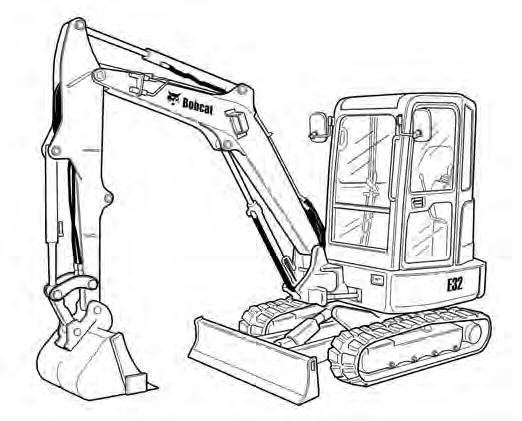
Falling-Object Guards (FOGS)
Figure5
Special Applications Kit
Figure6
Available for special applications that require protection from smaller objects that can fall on the canopy / cab or restrict material from entering canopy / cab openings [Figure5] and [Figure6]
The excavator must have the overhead guard [Figure5] installed to meet the top guard requirements in ISO 10262.
See your Bobcat Dealer for more information.
The excavator must have the special applications kit [Figure6] installed to meet the front guard requirements in FOGS ISO 10262 - level 1.
Kit includes an upper and lower screen guard.
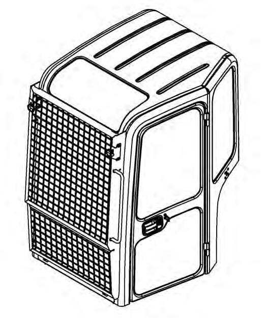
See your Bobcat Dealer for more information.
Special Applications Kit Inspection And Maintenance
The Special Applications Kit must be regularly inspected and maintained. Inspect the screen for damage. Replace parts as necessary.

SAFETY INSTRUCTIONS Before Operation
Carefully follow the operating and maintenance instructions in this manual.
The Bobcat excavator is highly maneuverable and compact. It is rugged and useful under a wide variety of conditions. This presents an operator with hazards associated with off highway, rough terrain applications, common with Bobcat excavator usage.
The Bobcat excavator has an internal combustion engine with resultant heat and exhaust. All exhaust gases can kill or cause illness so use the excavator with adequate ventilation.
The dealer explains the capabilities and restrictions of the Bobcat excavator and attachment for each application. The dealer demonstrates the safe operation according to Bobcat instructional materials, which are also available to operators. The dealer can also identify unsafe modifications or use of unapproved attachments. The attachments and buckets are designed for a Rated Lift Capacity. They are designed for secure fastening to the Bobcat excavator. The user must check with the dealer, or Bobcat literature, to determine safe loads of materials of specified densities for the machineattachment combination.
The following publications and training materials provide information on the safe use and maintenance of the Bobcat machine and attachments:
•The Delivery Report is used to assure that complete instructions have been given to the new owner and that the machine and attachment is in safe operating condition.
•The Operation & Maintenance Manual delivered with the machine or attachment gives operating information as well as routine maintenance and service procedures. It is a part of the machine and can be stored in a container provided on the machine. Replacement Operation & Maintenance Manuals can be ordered from your Bobcat dealer.
•Machine signs (decals) instruct on the safe operation and care of your Bobcat machine or attachment. The signs and their locations are shown in the Operation & Maintenance Manual. Replacement signs are available from your Bobcat dealer.

•An Operator’s Handbook is fastened to the operator cab of the excavator. It’s brief instructions are convenient to the operator. The handbook is available from your dealer in an English edition or one of many other languages. See your Bobcat dealer for more information on translated versions.
•The AEM Safety Manual delivered with the machine gives general safety information.
•The Compact Excavator Operating Training Course is available through your Bobcat dealer. This course is intended to provide rules and practices of correct operation of the Bobcat excavator. The course is available in English and Spanish versions.
•Service Safety Training Courses are available from your Bobcat dealer. They provide information for safe and correct service procedures.
•See the PUBLICATIONS AND TRAINING RESOURCES Page in this manual or your Bobcat dealer for Service and Parts Manuals, printed materials, videos, or training courses available. Also check the Bobcat web sites www.training.bobcat.com or www.bobcat.com
The dealer and owner / operator review the recommended uses of the product when delivered. If the owner / operator will be using the machine for a different application(s) he or she must ask the dealer for recommendations on the new use.
SAFETY INSTRUCTIONS (CONT’D)
Safe Operation Is The Operator’s Responsibility
Safety Alert Symbol
This symbol with a warning statement means: “Warning, be alert! Your safety is involved!” Carefully read the message that follows.
Warning
Operator must have instructions before operating the machine. Untrained operators can cause injury or death.
W-2001-0502
Important
This notice identifies procedures which must be followed to avoid damage to the machine.
I-2019-0284
Danger
The signal word DANGER on the machine and in the manuals indicates a hazardous situation which, if not avoided, will result in death or serious injury.
D-1002-1107
Warning
The signal word WARNING on the machine and in the manuals indicates a potentially hazardous situation which, if not avoided, could result in death or serious injury.
W-2044-1107
The Bobcat excavator and attachment must be in good operating condition before use.
Check all of the items on the Bobcat Service Schedule Decal under the 8-10 hour column or as shown in the Operation & Maintenance Manual.
Safe Operation Needs A Qualified Operator
For an operator to be qualified, he or she must not use drugs or alcoholic drinks which impair alertness or coordination while working. An operator who is taking prescription drugs must get medical advice to determine if he or she can safely operate a machine.
A Qualified Operator Must Do The Following:
Understand the Written Instructions, Rules and Regulations
•The written instructions from Bobcat Company include the Delivery Report, Operation & Maintenance Manual, Operator’s Handbook, Safety Manual and machine signs (decals).
•Check the rules and regulations at your location. The rules may include an employer’s work safety requirements. Regulations may apply to local driving requirements or use of a Slow Moving Vehicle (SMV) emblem. Regulations may identify a hazard such as a utility line.
Have Training with Actual Operation
•Operator training must consist of a demonstration and verbal instruction. This training is given by your Bobcat dealer before the product is delivered.
•The new operator must start in an area without bystanders and use all the controls until he or she can operate the machine and attachment safely under all conditions of the work area. Always fasten seat belt before operating.
•Operator Training Courses are available from your Bobcat dealer in English and Spanish. They provide information for safe and efficient equipment operation. Safety videos are also available.
•Service Safety Training Courses are available from your Bobcat dealer. They provide information for safe and correct service procedures.
Know the Work Conditions
•Know the weight of the materials being handled. Avoid exceeding the Rated Lift Capacity of the machine. Material which is very dense will be heavier than the same volume of less dense material. Reduce the size of load if handling dense material.
•The operator must know any prohibited uses or work areas, for example, he or she needs to know about excessive slopes.
•Know the location of any underground lines. Call local utilities or the TOLL FREE phone number found in the Before Operation section of this manual.
•Wear tight fitting clothing. Always wear safety glasses when doing maintenance or service. Safety glasses, respiratory equipment, hearing protection or Special Applications Kits are required for some work. See your Bobcat dealer about Bobcat safety equipment for your model.
SAFETY INSTRUCTIONS (CONT’D)
Avoid Silica Dust
Cutting or drilling concrete containing sand or rock containing quartz may result in exposure to silica dust. Do not exceed Permissible Exposure Limits (PEL) to silica dust as determined by OSHA or other job site Rules and Regulations. Use a respirator, water spray or other means to control dust. Silica dust can cause lung disease and is known to the state of California to cause cancer.
Fire Prevention
Maintenance
The machine and some attachments have components that are at high temperatures under normal operating conditions. The primary source of high temperatures is the engine and exhaust system. The electrical system, if damaged or incorrectly maintained, can be a source of arcs or sparks.
Flammable debris (leaves, straw, etc.) must be removed regularly. If flammable debris is allowed to accumulate, it can cause a fire hazard. Clean often to avoid this accumulation. Flammable debris in the engine compartment is a potential fire hazard.
The operator’s area, engine compartment and engine cooling system must be inspected every day and cleaned if necessary to prevent fire hazards and overheating.
All fuels, most lubricants and some coolant mixtures are flammable. Flammable fluids that are leaking or spilled onto hot surfaces or onto electrical components can cause a fire.
Operation
Do not use the machine where exhaust, arcs, sparks or hot components can contact flammable material, explosive dust or gases.
Electrical
Check all electrical wiring and connections for damage. Keep the battery terminals clean and tight. Repair or replace any damaged part or wires that are loose or frayed.
Battery gas can explode and cause serious injury. Use the procedure in the Operation & Maintenance Manual for connecting the battery and for jump starting. Do not jump start or charge a frozen or damaged battery. Keep any open flames or sparks away from batteries. Do not smoke in battery charging area. SI EXC-0913
FIRE PREVENTION (CONT’D)
Hydraulic System
Check hydraulic tubes, hoses and fittings for damage and leakage. Never use open flame or bare skin to check for leaks. Hydraulic tubes and hoses must be properly routed and have adequate support and secure clamps. Tighten or replace any parts that show leakage.
Always clean fluid spills. Do not use gasoline or diesel fuel for cleaning parts. Use commercial nonflammable solvents.
Fueling
Stop the engine and let it cool before adding fuel. No smoking! Do not refuel a machine near open flames or sparks. Fill the fuel tank outdoors.
Ultra Low Sulfur Diesel (ULSD) poses a greater static ignition hazard than earlier diesel formulations with higher Sulfur content. Avoid death or serious injury from fire or explosion. Consult with your fuel or fuel system supplier to ensure the delivery system is in compliance with fueling standards for proper grounding and bonding practices.
Starting
Do not use ether or starting fluids on any engine that has glow plugs or air intake heater. These starting aids can cause explosion and injure you or bystanders.
Use the procedure in the Operation & Maintenance Manual for connecting the battery and for jump starting.
Spark Arrester Exhaust System
The spark arrester exhaust system is designed to control the emission of hot particles from the engine and exhaust system, but the muffler and the exhaust gases are still hot.
Check the spark arrester exhaust system regularly to make sure it is maintained and working properly. Use the procedure in the Operation & Maintenance Manual for cleaning the spark arrester muffler (if equipped).
Welding And Grinding
Always clean the machine and attachment, disconnect the battery, and disconnect the wiring from the Bobcat controllers before welding. Cover rubber hoses, battery and all other flammable parts. Keep a fire extinguisher near the machine when welding.
Have good ventilation when grinding or welding painted parts. Wear dust mask when grinding painted parts. Toxic dust or gas can be produced.
Dust generated from repairing nonmetallic parts such as hoods, fenders or covers can be flammable or explosive. Repair such components in a well ventilated area away from open flames or sparks.
Fire Extinguishers
Know where fire extinguishers and first aid kits are located and how to use them. Inspect the fire extinguisher and service the fire extinguisher regularly. Obey the recommendations on the instructions plate.
Publications And Training Resources
The following publications are also available for your Bobcat excavator. You can order them from your Bobcat dealer.
For the latest information on Bobcat products and the Bobcat Company, visit our web site at www.bobcat.com; you can also order Operator and Service Training materials online through www.bobcatstore.com
OPERATION & MAINTENANCE MANUAL
7252734enUS
- Complete instructions on the correct operation and the routine maintenance of the BOBCAT excavator.
SERVICE MANUAL
6987272enUS
- Complete maintenance instructions for your BOBCAT Excavator.
SAFETY MANUAL (English & Spanish)

6901951
- Provide basic safety procedures and warnings for your BOBCAT excavator in both English and Spanish.
OPERATOR’S HANDBOOK
6990434enUS COMPACT EXCAVATOR OPERATOR TRAINING COURSE
Gives basic operation instructions and safety warnings
6903186
Introduces operator to step-by-step basics of Compact Excavator operation. Also available in Spanish P/N 6903228

EXCAVATOR SERVICE SAFETY COURSE
6900916
Introduces Service Technicians to step-by-step basics of proper and safe excavator maintenance and servicing procedures
OPERATOR SAFETY DVD
6904762
Provides basic safety instructions contained in all Bobcat Safety Videos in both English and Spanish.
EXCAVATOR SAFETY VIDEO
(Mobile device with quick response code application required)
Scan the code above to watch the excavator safety video or view at www.training.bobcat.com
MACHINE SIGNS (DECALS) (EXCAVATORS WITH PICTORIAL ONLY DECALS)
Follow the instructions on all the Machine Signs (Decals) that are on the excavator. Replace any damaged machine signs and be sure they are in the correct locations. Machine signs are available from your Bobcat excavator dealer.
MACHINE SIGNS (DECALS) (EXCAVATORS WITH PICTORIAL ONLY DECALS) (CONT’D)

Pictorial Only Safety Signs
Safety signs are used to alert the equipment operator or maintenance person to hazards that may be encountered in the use and maintenance of the equipment. The location and description of the safety signs are detailed in this section. Please become familiarized with all safety signs installed on the excavator.
Vertical Configuration
NOTE: See the numbered MACHINE SIGNS (DECALS) (EXCAVATORS WITH PICTORIAL ONLY DECALS) on Page 20 and MACHINE SIGNS (DECALS) (EXCAVATORS WITH PICTORIAL ONLY DECALS) (CONT’D) on Page 21 for the machine location of each corresponding numbered no-text decals as shown below.
1.Motion Alarm (7136738)
This safety sign is located on the right rear console.
HAZARD PANEL
AVOIDANCE PANEL
Horizontal Configuration
Warning
This machine is equipped with a motion alarm. ALARM MUST SOUND! when operating forward or backward.
HAZARD PANEL AVOIDANCE PANEL
The format consists of the hazard panel(s) and the avoidance panel(s):
Hazard panels depict a potential hazard enclosed in a safety alert triangle.

Avoidance panels depict actions required to avoid the hazards.
A safety sign may contain more than one hazard panel and more than one avoidance panel.
Failure to maintain a clear view in the direction of travel could result in serious injury or death.
The operator is responsible for the safe operation of this machine.
W-2786-0309
MACHINE SIGNS (DECALS) (EXCAVATORS WITH PICTORIAL ONLY DECALS) (CONT’D)
Pictorial Only Safety Signs (Cont’d)
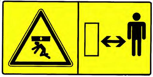
2.Crush Hazard (6713507)
This safety sign is located on both sides of the boom.
Warning
Keep away from the operating machine to avoid serious injury or death.
W-2520-0106
3.Thrown Or Flying Objects (7168039)
This safety sign is located on the outside of both tracks.
4.Transporting And Lifting (7178215)
This safety sign is located on the front of the cab.
Warning
High pressure grease can cause serious injury. Do not loosen grease fitting. Do not loosen bleed fitting more than 1 - 1/2 turns.
Read and understand the Operation & Maintenance Manual for more information.
W-2516-0110
Warning
Improper loading, transporting and lifting procedures can cause serious injury or death. Read and understand the Operation & Maintenance Manual prior to transporting or lifting the machine.
W-2517-0110
MACHINE SIGNS (DECALS) (EXCAVATORS WITH PICTORIAL ONLY DECALS) (CONT’D)
Pictorial Only Safety Signs (Cont’d)
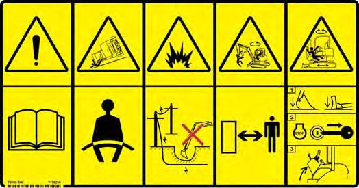
5.General Hazard (7148158, 7178216)
This safety sign is located inside the operator’s area on the right rear window.
Warning
Failure to obey warning signs and instructions can cause serious injury or death. Never use excavator without instructions. Read and understand the Operation & Maintenance Manual and Handbook.
Keep away from dropoffs, steep areas or banks that could break away.
Explosion or electrocution can occur if machine contacts utility lines or pipes. Check for overhead or underground lines before operating.
Keep bystanders away. No riders. Check location of blade for direction of travel before moving steering controls.
Failure to operate machine from the operator’s position can cause serious injury or death.
To Leave Excavator:
1. Lower attachment and blade to ground.
2. Stop engine and remove the key (if equipped).
3. Raise control console.
W-2518-0110
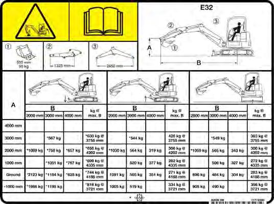
6.Lift Capacity (7177236, 7177237, 7182362)
This safety sign is located on the right side cover.
Warning
Overload can tip the excavator and cause serious injury or death.
•Do not lift or hold any load that exceeds these ratings at their specific load radii and height.
•Total rated load is shown. The weight of all lifting devices must be deducted to determine the net load that can be lifted.
Read and understand the Operation & Maintenance Manual for more information.
W-2519-0110
MACHINE SIGNS (DECALS) (EXCAVATORS WITH PICTORIAL ONLY DECALS) (CONT’D)
Pictorial Only Safety Signs (Cont’d)
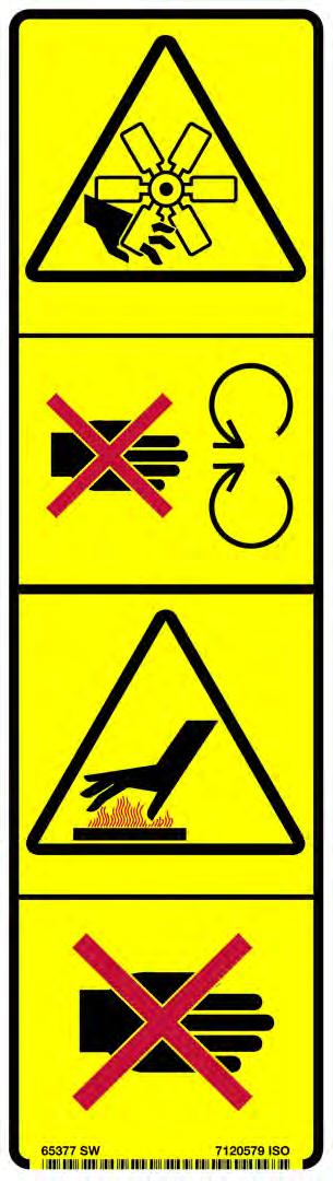
7.Hot Surfaces and Rotating Fan (7243563)
This safety sign is located inside the engine compartment.
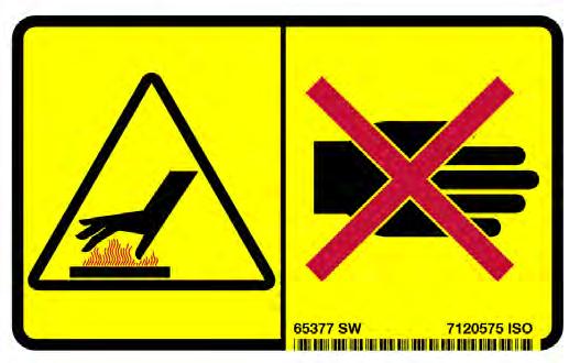
8.Hot Surfaces (7185935)
This safety sign is located in the engine compartment.
Warning
Rotating fan blade can cause serious injury or death. Keep away from fan and moving parts. Do not operate with guard removed.
Hot surfaces can cause injury. Do not touch. Allow to cool before servicing.
W-2521-0106
Warning
AVOID BURNS
Do not remove radiator cap when the engine is hot. You can be seriously burned.
W-2070-1203
MACHINE SIGNS (DECALS) (EXCAVATORS WITH PICTORIAL ONLY DECALS) (CONT’D)
Pictorial Only Safety Signs (Cont’d)
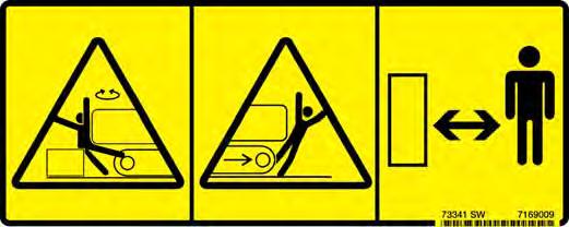
9.Stay Away (7169009)
This safety sign is located on both upper rear corners of the upperstructure.
Warning
AVOID INJURY OR DEATH
•Keep out of swing area or travel path.
•Always look in the direction of travel.
•Make sure swing area is clear of bystanders and objects.
W-2775-1208
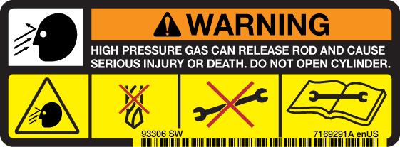
10.Thrown or Flying Objects (7169291)
This safety sign is located on the gas spring under the rear cover.
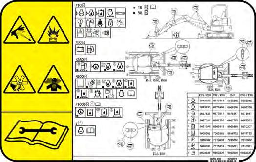
11.High Pressure, Battery, Rotating Fan, Exhaust Gases and Service Schedule (7238019)
This safety sign is located on the right front corner of the upperstructure. For Service Schedule Information, (See SERVICE SCHEDULE on Page 107.)
Warning
7169291
Warning
Leaking fluids under pressure can enter the skin and cause serious injury or death. Immediate medical attention is required. Wear goggles. Use cardboard to check for leaks.
Battery makes flammable and explosive gas. Keep arcs, sparks, flames and lighted tobacco away. Keep away from electrical contacts
Rotating fan can cause serious injury. Keep away from fan and moving parts. Do not operate with guard removed.
All exhaust gases can kill. Always ventilate.
Read and understand the Operation & Maintenance Manual for more information.
W-2522-0110
High pressure gas can cause serious injury or death. Do not open. Opening cylinder can release rod.
W-2523-0106
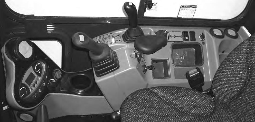
Instruments And Consoles
REF. NO. DESCRIPTION FUNCTION / OPERATION
1 Left Joystick(See HYDRAULIC CONTROLS on Page 52.)
2 HornPress the switch on the bottom of the left joystick to sound horn.
3 Boom Swing Switch / Secondary Auxiliary Hydraulic (If Equipped)
4 Wiper / Washer Switch (If Equipped)
Move the switch to the left to swing the boom to the left. Move the switch to the right to swing the boom to the right. (See Secondary Auxiliary Hydraulics and Boom Swing in this manual.)
Press the switch to the left to turn wiper ON. Press and hold switch to the left to activate window washer. Press the switch to the right to turn wiper OFF.
5 Not Used- - -
6 Beacon / Strobe Light (If Equipped)
Press switch to the left to turn ON the beacon / Strobe light. Press the switch to the right to turn OFF.


7 Not Used- - -
8 Not Used- - -
9 Boom Swing Switch / Secondary Auxiliary Hydraulic (If Equipped)
Move the switch to the right to activate the secondary auxiliary hydraulics. Move the switch to the left for boom swing function. (See Secondary Auxiliary Hydraulics and Boom Swing in this manual.)
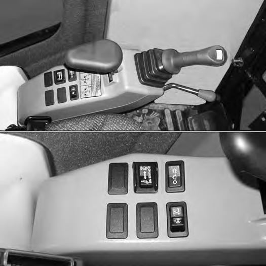
INSTRUMENTS AND CONSOLES (CONT’D)
Right Console
Figure10
REF DESCRIPTION
FUNCTION / OPERATION
1 Right Joystick(See HYDRAULIC CONTROLS in this manual.)
2 Auxiliary Hydraulic SwitchControls the fluid flow to the auxiliary quick couplers (attachment). (See Auxiliary Hydraulics in this manual.)
3 Blade Control LeverControls raising and lowering the blade. Pushed all the way forward puts blade in float position. (See BLADE LEVER CONTROL in this manual).
4 Engine Speed Control DialControls rpm of the engine. (See ENGINE SPEED CONTROL DIAL in this manual).
5 Two-Speed ButtonEngages and disengages High Range Travel Speed. (See Two-Speed Travel in this manual).
6 Motion Alarm Cancel SwitchThis switch temporarily disables the motion alarm. (See MOTION ALARM SYSTEM on Page 49.)
7 Not Used---
8 Auxiliary Power Outlet12 volt receptacle for accessories.
9 Key SwitchAlways perform the PRE-STARTING PROCEDURE. (See PRE-STARTING PROCEDURE in this manual), before starting the engine. (See STARTING THE ENGINE in this manual).
10 Air Conditioning Switch (If Equipped)
Press top of switch to turn air conditioner ON (light in switch will be ON), Press bottom of switch to turn OFF.
11 Fan Motor Switch (If Equipped)Turn clockwise to increase fan speed; counterclockwise to decrease.
12 Temperature Control (If Equipped) Turn clockwise to increase temperature; counterclockwise to decrease.
13 Instrument PanelSee Standard or Deluxe Instrument Panel
14 Keyless (If Equipped)(Always perform the PRE-STARTING PROCEDURE, (See PRE-STARTING PROCEDURE in this manual), before starting the engine. (See STARTING THE ENGINE in this manual).
NOTE:Always turn key switch and all accessories to OFF position when the engine is stopped, the battery will discharge if the key is left ON.
INSTRUMENTS AND CONSOLES (CONT’D)
Instrument Panel - Standard
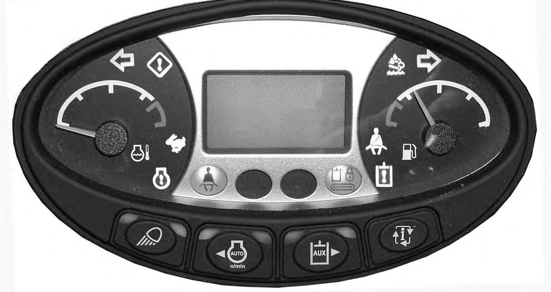
Figure11
REF. NO. DESCRIPTION
FUNCTION / OPERATION
1 LIGHTSPress once for work lights. (Left green LED illuminates.) Press again to turn all lights off. (Left green LED off.)
Press and hold 5 seconds to display software version in display screen.
2 Auto Idle FeaturePress once to turn Auto Idle Feature ON. (Left green LED illuminates.) Press a second time to turn OFF. (Left and right green LEDs off.) (See Auto Idle Feature in this manual).
3 Auxiliary Hydraulic Button Press once to enable auxiliary hydraulic function. (Left green LED illuminates.) Continue to press and release to scroll through the selectable auxiliary hydraulic setting (3-2-1-OFF).
Press and hold (minimum of one second) to enable the continuous flow auxiliary hydraulic feature. (Right green LED illuminates.) Continue to press and release to scroll through the continuous flow selectable auxiliary hydraulic settings (3-2-1-OFF).
(See Auxiliary Hydraulics in this manual)
4 Information Cycles through (after each button press) (The following information is displayed in the Data Display Screen, Item 6):
•Hourmeter (On startup)
•Job Clock (1 and 2) (Press and hold 7 seconds when displayed to reset the job clock.)
•Engine rpm
•Battery voltage
•Maintenance clock (Press and hold 7 seconds when displayed to reset the maintenance clock.)
•Service codes*
INSTRUMENTS AND CONSOLES (CONT’D)
Instrument Panel - Standard (Cont’d)
REF. NO.
Description
FUNCTION / OPERATION
6 Data Display ScreenThe data display screen shows the Hourmeter at start up and then changes to engine rpm during normal operation of the excavator. When preheat is activated, the display screen will show the remaining preheat time. Can also be used to display Job Clock, Engine rpm, and Selectable Auxiliary Hydraulic Flow. (See Job Clock in this manual).
7 Fuel GaugeShows the amount of fuel in the tank.
8 Seat BeltFasten Seat Belt Reminder - Light stays on for 45 seconds to remind operator to fasten seat belt.
11 Left Console LockoutIcon ON when left console is raised. Icon OFF when left console is lowered.
12 General Warning **Malfunction with one or more machine functions. (See Service Codes in this manual.)
13 High Range Engaged ***Icon is illuminated when two-speed travel is enabled.
Engine Coolant Temperature **Engine coolant temperature high or sensor error.
or error. (Icon is ON when fuel level is low, Icon flashes when fuel sensor fault is activated.)
* See SYSTEM SETUP AND ANALYSIS for Service Code Description. (See DIAGNOSTIC SERVICE CODES on Page 155.)
** Icons will be ON or flashing when diagnostic system indicates a problem. (See DIAGNOSTIC SERVICE CODES on Page 155.)
*** Icons will be flashing when diagnostic system indicates a problem. (See DIAGNOSTIC SERVICE CODES on Page 155.)
INSTRUMENTS AND CONSOLES (CONT’D)
Instrument Panel - Standard (Cont’d)
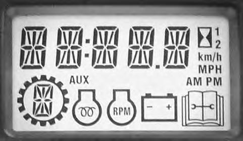
Indicator Icons
The display screen can display the following information:
•Operating hours
•Job Clock (1 and 2)
•Engine rpm
•Battery voltage
•Maintenance clock countdown
•Service codes
The display screen is shown in [Figure12]. The data display will show operating hours upon startup.