15 minute read
ELECTRICAL SYSTEM


Description
Figure187
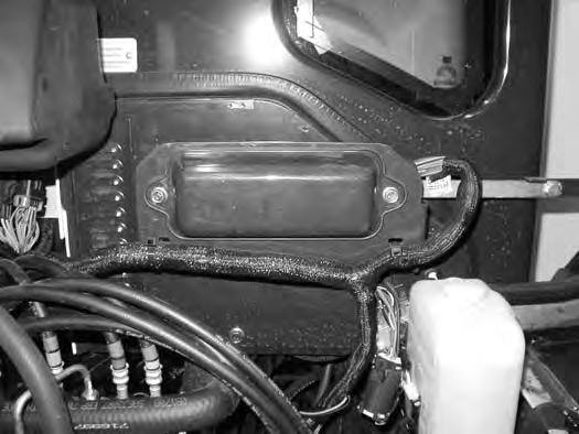
The excavator has a 12 volt, negative ground electrical system. The electrical system is protected by fuses located under the right side cover of the excavator (Item 1) [Figure187]. The fuses will protect the electrical system when there is an electrical overload. The reason for the overload must be found and corrected before starting the engine again.
The battery cables must be clean and tight. Check the electrolyte level in the battery. Add distilled water as needed. Remove acid or corrosion from the battery and cables with a sodium bicarbonate and water solution.
Put Battery Saver P/N 6664458 or grease on the battery terminals and cable ends to prevent corrosion.
Warning
AVOID INJURY OR DEATH
Batteries contain acid which burns eyes and skin on contact. Wear goggles, protective clothing and rubber gloves to keep acid off body.
In case of acid contact, wash immediately with water. In case of eye contact get prompt medical attention and wash eye with clean, cool water for at least 15 minutes.
If electrolyte is taken internally drink large quantities of water or milk! DO NOT induce vomiting. Get prompt medical attention.
W-2065-0807
Fuse And Relay Location / Identification
A decal is inside the fuse cover to show location and amp ratings.
Remove the cover to check or replace the fuses and relays.
The location and sizes are shown in [Figure 188]
Always replace fuses using the same type and capacity.
ELECTRICAL SYSTEM (CONT’D)

ELECTRICAL SYSTEM (CONT’D)
Shut-Off Switch
Open the right side cover. (See RIGHT SIDE COVER on Page 114.)
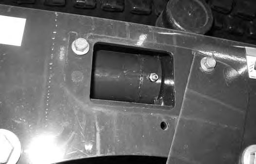
Figure189
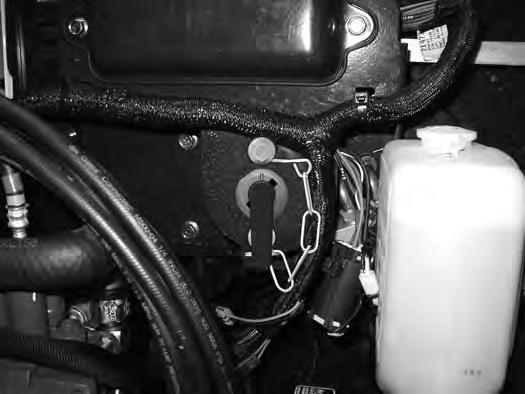
The shut-off switch (Item 1) [Figure189] is located under the right side cover below the fuse panel.
Rotate the switch (Item 1) anticlockwise to turn the switch to the OFF position, clockwise to turn to the ON position.
Battery Maintenance
Open the right side cover. (See RIGHT SIDE COVER on Page114.)
Figure190
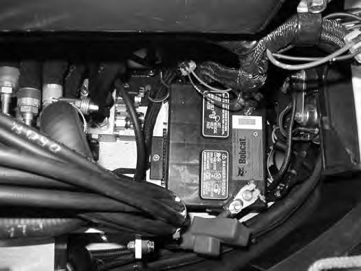
The battery (Item 1) [Figure190] is located in the front of the right side upperstructure.
Figure191
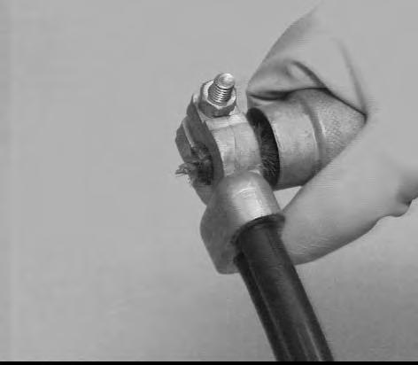
The battery cables must be clean and tight [Figure191] Remove acid or corrosion from the battery and cables using a sodium bicarbonate and water solution. Cover the battery terminals and cable ends with battery saver grease to prevent corrosion.
Check for broken or loose connections.
If the battery cables are removed for any reason, disconnect the negative (-) cable first. When installing the battery cables, make the last connection the negative (-) cable to the battery.
The original equipment battery is maintenance free. If a replacement battery is installed, check the electrolyte level in the battery.

If the electrolyte level is lower than 13 mm (0.50 in) above the plates, add distilled water only.

Warning
AVOID INJURY OR DEATH
Batteries contain acid which burns eyes and skin on contact. Wear goggles, protective clothing and rubber gloves to keep acid off body.
In case of acid contact, wash immediately with water. In case of eye contact get prompt medical attention and wash eye with clean, cool water for at least 15 minutes.
If electrolyte is taken internally drink large quantities of water or milk! DO NOT induce vomiting. Get prompt medical attention.
W-2065-0807
ELECTRICAL SYSTEM (CONT’D)
Using A Booster Battery (Jump Starting)
Important
If jump starting the excavator from a second machine:
When jump starting the excavator from a battery installed in a second machine, make sure the engine is NOT running while using the glow plugs. High voltage spikes from a running machine can burn out the glow plugs.
I-2060-0906
If it is necessary to use a booster battery to start the engine, BE CAREFUL! There must be one person in the operator’s seat and one person to connect and disconnect the battery cables.
Be sure the key switch is OFF. The booster battery must be 12 volt.
Open the tailgate. (See TAILGATE on Page113.)
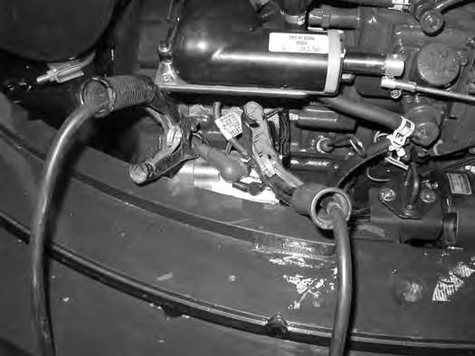
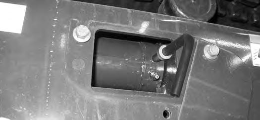
Disconnect the cable from the excavator starter (Item 1) [Figure192].
NOTE: (See Cold Temperature Starting on Page 73.)
Important
Damage to the alternator can occur if:
•Engine is operated with battery cables disconnected.
•Battery cables are connected when using a fast charger or when welding on the excavator. (Remove both cables from the battery.)
•Extra battery cables (booster cables) are connected wrong.
I-2223-0903
Warning
AVOID INJURY OR DEATH
Batteries contain acid which burns eyes and skin on contact. Wear goggles, protective clothing and rubber gloves to keep acid off body.
In case of acid contact, wash immediately with water. In case of eye contact get prompt medical attention and wash eye with clean, cool water for at least 15 minutes.
If electrolyte is taken internally drink large quantities of water or milk! DO NOT induce vomiting. Get prompt medical attention.
W-2065-0807
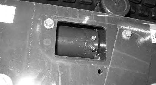
Connect one end of the first cable to the positive (+) terminal of the booster battery. Connect the other end of the same cable to the positive (+) terminal (Item 1) [Figure192] of the excavator starter.
Connect one end of the second cable to the negative (-) terminal of the booster battery. Connect the other end of the same cable to the starter mounting bolt (Item 2) [Figure192]
Start the engine. After the engine has started, remove the ground (-) cable first (Item 2) [Figure192]
ELECTRICAL SYSTEM (CONT’D)
Removing And Installing The Battery
Open the right side cover. (See RIGHT SIDE COVER on Page114.)
Figure193
Warning
Avoid Injury Or Death
Batteries contain acid which burns eyes and skin on contact. Wear goggles, protective clothing and rubber gloves to keep acid off body.
In case of acid contact, wash immediately with water. In case of eye contact get prompt medical attention and wash eye with clean, cool water for at least 15 minutes.
If electrolyte is taken internally drink large quantities of water or milk! DO NOT induce vomiting. Get prompt medical attention.
Disconnect the negative (-) cable (Item 1) [Figure193] first.
Disconnect the positive (+) cable (Item 2) [Figure193]
Remove the bolt (Item 3) [Figure193] and remove the hold-down clamp.
Remove the battery.
Always clean the terminals and the cable ends, even when installing a new battery.
Install the battery. Install the hold-down clamp and tighten the bolts.
Connect the battery cables. Connect the negative (-) cable (Item 1) [Figure193] last to prevent sparks.
Hydraulic System
Checking And Adding Hydraulic Oil
Put the machine on a flat level surface. Retract the arm and bucket cylinders, put the bucket on the ground and lower the blade. Stop the engine.
Open the right side cover. (See RIGHT SIDE COVER on Page114.)
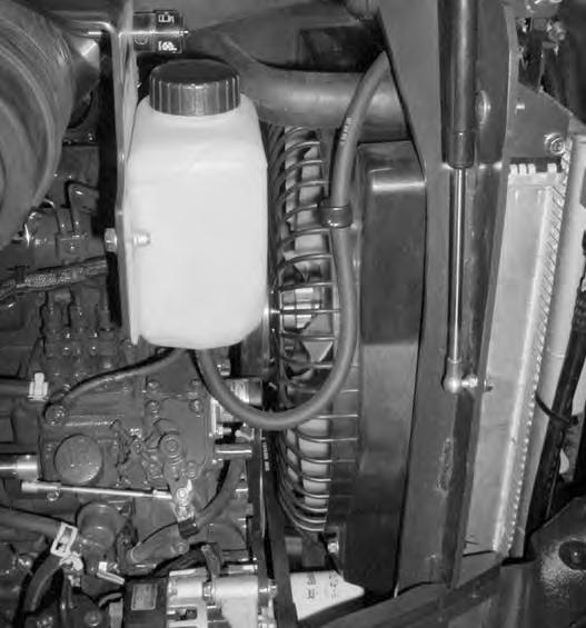
Figure194
Park the machine in the position shown [Figure194]

(The preferred method is to check the hydraulic oil when it is cold.)
Check the hydraulic oil level, it must be visible in the sight gauge (Item 1) [Figure194]. The decal on the hydraulic tank shows the correct fill level.

A - Correct Oil Level COLD (Preferred)
B - Correct Oil Level HOT (Optional)
Clean the surface around the reservoir cap and remove the cap from the reservoir (Item 2) [Figure194]
Warning
AVOID INJURY OR DEATH
Always clean up spilled fuel or oil. Keep heat, flames, sparks or lighted tobacco away from fuel and oil. Failure to use care around combustibles can cause explosion or fire.
W-2103-0508
Figure195
Check the condition of the fill strainer screen (Item 1) [Figure195]. Clean or replace as necessary.
Be sure the screen is installed before adding fluid.
Add the correct fluid to the reservoir until it is visible in the sight gauge. (See HYDRAULIC SYSTEM on Page133.)

Check the cap and clean as necessary. Replace the cap if damaged.
Install the cap.
Close the right side cover and tailgate.
Hydraulic / Hydrostatic Fluid Chart
Figure196
HYDRAULIC / HYDROSTATIC FLUID RECOMMENDED ISO VISCOSITY GRADE (VG) AND VISCOSITY INDEX (VI)
TEMPERATURE RANGE ANTICIPATED DURING MACHINE USE
[1] VG 100; Minimum VI 130
[2] VG 46; Minimum VI 150
[3] BOBCAT All-Season Fluid
[4] BOBCAT Synthetic Fluid
[5] BOBCAT Biodegradable Hydraulic / Hydrostatic Fluid (Unlike biodegradable fluids that are vegetable based, Bobcat biodegradable fluid is formulated to prevent oxidation and thermal breakdown at operating temperatures.)
Install the oil fill cap.
HYDRAULIC SYSTEM (CONT’D)
Removing And Replacing The Hydraulic Filters

Hydraulic Filter
Warning
AVOID INJURY OR DEATH
Always clean up spilled fuel or oil. Keep heat, flames, sparks or lighted tobacco away from fuel and oil. Failure to use care around combustibles can cause explosion or fire.
W-2103-0508
See the SERVICE SCHEDULE for the correct service interval. (See SERVICE SCHEDULE on Page 107.)
Remove the hydraulic filter (Item 1) [Figure198]
Clean the housing where the filter gasket makes contact.
Put clean hydraulic fluid on the gasket. Install the new filter and hand tighten only. Use a genuine Bobcat replacement filter.
For easier access to change the hydraulic filter, remove the lower right side panel.
Remove the four bolts (Item 1) and the side panel (Item 2) [Figure197]. Remove the side panel.
Open the right side cover. (See RIGHT SIDE COVER on Page114.)

HYDRAULIC SYSTEM (CONT’D)
Removing And Replacing The Hydraulic Filters (Cont’d)
Case Drain Filter
Warning
AVOID INJURY OR DEATH
Always clean up spilled fuel or oil. Keep heat, flames, sparks or lighted tobacco away from fuel and oil. Failure to use care around combustibles can cause explosion or fire.
W-2103-0508
See the SERVICE SCHEDULE for the correct service interval. (See SERVICE SCHEDULE on Page 107.)
The case drain filter is located below the floorplate. Remove the floor mat.
Remove the floorplate.
Figure199
Remove the case drain filter (Item 1) [Figure199]
Clean the housing where the filter gasket makes contact. Put clean hydraulic fluid on the gasket. Install the new filter and hand tighten only.
NOTE:When changing the case drain filter, also lubricate the boom swing cylinder base end fitting while the floorplate is removed. (See SERVICE SCHEDULE on Page 107.) and (See LUBRICATION OF THE HYDRAULIC EXCAVATOR on Page 147.)
HYDRAULIC SYSTEM (CONT’D)
Removing And Replacing The Hydraulic Fluid
See the SERVICE SCHEDULE for the correct service interval. (See SERVICE SCHEDULE on Page 107.)
Warning
Avoid Injury Or Death
Diesel fuel or hydraulic fluid under pressure can penetrate skin or eyes, causing serious injury or death. Fluid leaks under pressure may not be visible. Use a piece of cardboard or wood to find leaks. Do not use your bare hand. Wear safety goggles. If fluid enters skin or eyes, get immediate medical attention from a physician familiar with this injury.
W-2072-0807
Retract the arm and bucket cylinders, lower the bucket to the ground. Stop the engine.
Open the tailgate. (See TAILGATE on Page 113.)
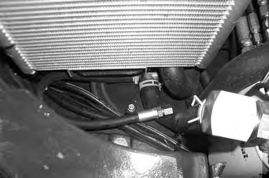
Figure200
The hydraulic oil drain hose (Item 1) [Figure200] is located below the oil cooler in the right rear corner of the upperstructure.
Figure201
Reposition the drain hose out the bottom of the upperstructure and remove the cap (Item 1) [Figure201]
Drain the fluid into a container.
Recycle or dispose of the fluid in an environmentally safe manner.
Install the cap (Item 1) [Figure201] and position the drain hose back to the storage position (Item 1) [Figure200]
Add fluid to the reservoir. (See HYDRAULIC SYSTEM on Page 133.)
Figure202
With the engine OFF, loosen the plug (Item 1) [Figure202] on the hydraulic pump. Tighten the plug after a steady stream of hydraulic fluid, free of any air bubbles, drains from the plug. DO NOT RUN THE MACHINE WITH THE PLUG OPEN.

Figure203
There is also a port (Item 1) [Figure203] on the hydraulic cooler for bleeding air. Install a diagnostic coupler and hose on this fitting to allow air to be bled from the hydraulic system after the hydraulic fluid has been replaced.

Start the engine and operate the machine through the hydraulic functions. Stop the engine. Check the fluid level and add as needed.
SPARK ARRESTER MUFFLER Cleaning Procedure
If equipped with the spark arrester muddler, See the SERVICE SCHEDULE for the correct service interval.
(See SERVICE SCHEDULE on Page 107.)
Warning
Avoid Injury Or Death
When an engine is running in an enclosed area, fresh air must be added to avoid concentration of exhaust fumes. If the engine is stationary, vent the exhaust outside. Exhaust fumes contain odorless, invisible gases which can kill without warning.
W-2050-0807
Warning
Stop engine and allow the muffler to cool before cleaning the spark chamber. Wear safety goggles. Failure to obey can cause serious injury.
W-2011-1285
Warning
Never use machine in atmosphere with explosive dust or gases or where exhaust can contact flammable material. Failure to obey warnings can cause injury or death.

W-2068-1285
Warning
When the engine is running during service, the steering levers must be in neutral.
Failure to do so can cause injury or death.
W-2203-0595
Do not operate the excavator with a defective exhaust system.
Stop the engine. Open the tailgate. (See TAILGATE on Page 113.)
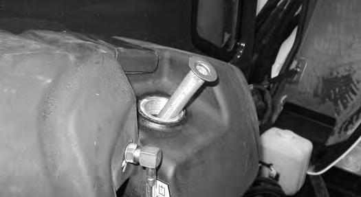
The left panel (Item 1) [Figure204] will need to be removed for access to the spark arrester muffler.
Remove the fuel cap (Item 2) and the four bolts (Item 3) and remove the panel (Item 1) [Figure204].
Reinstall the fuel cap (Item 2) [Figure204]
Figure205
Remove the plug (Item 1) [Figure205] from the bottom of the muffler.
Start the engine and run for about 10 seconds while a second person, wearing safety glasses, holds a piece of wood over the outlet of the muffler. The carbon deposits will be forced out of the muffler plug hole (Item 1) [Figure205]
Stop the engine. Install and tighten the plug.
Reinstall the panel (Item 1) [Figure204]
Close the tailgate.
Track Tension
NOTE: The wear of the pins and bushings on the undercarriage vary with the working conditions and the different types of soil conditions. It is necessary to inspect track tension and maintain the correct tension. See SERVICE SCHEDULE for the correct service interval. (See SERVICE SCHEDULE on Page 107.)
Adjusting
Figure206
Warning
AVOID INJURY
Keep fingers and hands out of pinch points when checking the track tension.
W-2142-0903
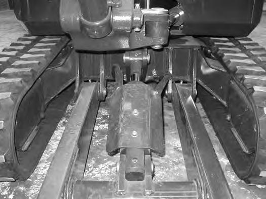
Raise one side of the machine (Approximately four inches) using the boom and arm.
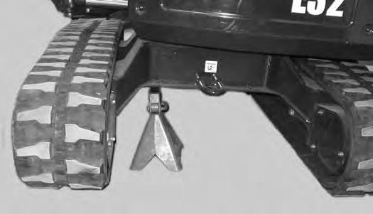
Raise the blade fully and install jackstands under the blade and track frame (Item 1) [Figure206]. Lower the boom until all machine weight is on the jackstands.
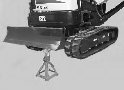
Stop the engine.
TRACK TENSION (CONT’D)
Adjusting (Cont’d)
Rubber Track Clearance
Figure207
10 - 15 mm (0.39 - 0.59 in)
Steel Track Clearance
Figure209
17,3 - 30 mm
(0.68 - 1.18 in)
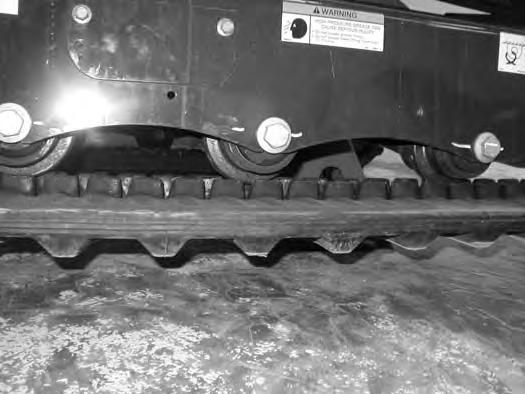
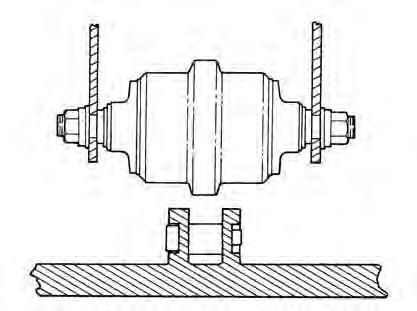
Measure the track clearance at the middle track roller. Do not get fingers into pinch points between the track and the track roller. Us a bolt or dowel of the appropriate size to check the gap between the contact edge of the roller and the top edge of the track guide [Figure209]
Steel Track Clearance - 17,3 - 30 mm (0.68 - 1.18 in)
10 - 15 mm (0.39 - 0.59 in)
Measure the clearance at the middle track roller. Do not get fingers into pinch points between the track and the track roller. Use a bolt or a dowel of the appropriate size to check the gap between the contact edge of the roller and the top edge of the track guide [Figure207] and [Figure208].
Rubber Track Clearance - 10 - 15 mm (0.39 - 0.59 in)
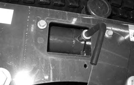
Loosen the two bolts from the cover (Item 1) [Figure210]. Pivot the cover downward.
TRACK TENSION (CONT’D)
Adjusting (Cont’d)
Warning
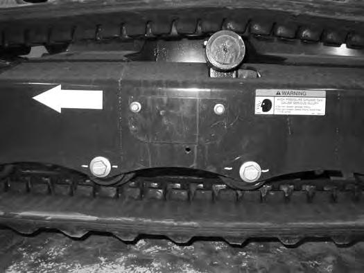
HIGH PRESSURE GREASE CAN CAUSE SERIOUS INJURY •Do not loosen the track tension fitting more than 1 - 1/2 turns.
W-2994-0515
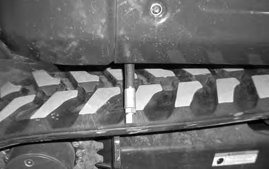
With Bleed Screw and Track Tension Fitting
Figure211
Add grease to the track tension fitting (Item 1) [Figure211] until the track tension is correct.
Figure212
The tension removal tool (P/N 6675936) is available and recommended to direct the flow of grease to aid in cleanup. Always dispose of the grease in an environmentally friendly manor.
The tool is sized to fit the bleed fitting (Item 2) [Figure211]
Use tool P/N 6675936 (Item 1) [Figure212] to loosen the bleed fitting (Item 2) [Figure211] to release tension from the track. Do not loosen the bleed fitting more than 1-1/2 turns.
NOTE: Do not loosen the track tension fitting (Item 1) [Figure211].
Repeat the procedure for the other side.
With One Piece - Track Tension Fitting
Figure213
Add grease to the track tension fitting (Item 1) [Figure213] until the track tension is correct.
The tension removal tool (P/N 7277225) is available and recommended to direct the flow of grease to aid in cleanup. Always dispose of the grease in an environmentally friendly manor.
The tool is sized to fit the one piece track tension fitting (Item 1) [Figure213]
Use tool P/N 7277225 (Item 1) [Figure214] to loosen the track tension fitting (Item 1) [Figure213] to release tension from the track.
NOTE: Do not loosen the track tension fitting (Item 1) [Figure213] more than 1-1/2 turns.
Installation: Tighten the track tension fitting to 23 N•m (17 ft-lb) torque.
Repeat the procedure for the other side.
Travel Motor
Checking And Adding Oil
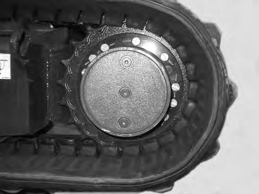
Figure215
Park the excavator on a level surface with the plugs (Items 1 and 2) [Figure215] in the vertical position as shown.
Remove the plug (Item 1) [Figure215]. The lube level must be at the bottom edge of the hole.
Add lubricant (SAE 90W) through the hole if the lube level is low.
Removing And Replacing Oil
See the SERVICE SCHEDULE for the correct service interval. (See SERVICE SCHEDULE on Page 107.)
Park the excavator on a level surface with plugs (Items 1 and 2) [Figure215] in the vertical position shown. Remove both plugs and drain the lubricant into a container.
Warning
Avoid Injury Or Death
Always clean up spilled fuel or oil. Keep heat, flames, sparks or lighted tobacco away from fuel and oil. Failure to use care around combustibles can cause explosion or fire.
Install the bottom plug (Item 2) [Figure215]. Add lubricant through the center plug hole until the lube level is at the bottom edge of the hole.
Add lubricant (SAE 90W) through the hole if the lube level is low.
Install the plug (Item 1) [Figure215]
ALTERNATOR BELT Belt Adjustment
The alternator belt is a special maintenance free type that is pretensioned over the pulleys. This belt eliminates the need for a tensioning device and does not require periodic adjustment. Contact your Bobcat dealer for replacement parts.
Belt Replacement
Stop the engine and open the tailgate. (See TAILGATE on Page113.)
FAN BELT Belt Adjustment
The fan belt is a special maintenance free type that is pretensioned over the pulleys. This belt eliminates the need for a tensioning device and does not require periodic adjustment. Contact your Bobcat dealer for replacement parts.
Belt Replacement
Stop the engine and open the tailgate. (See TAILGATE on Page113.)
Remove the alternator belt. (See ALTERNATOR BELT on Page142.)
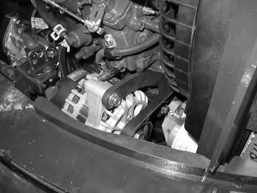
Loosen the bolt (Item1) [Figure216] and the lower alternator mounting bolt and nut (not shown).
Use a pry bar to take the pressure off of the bolt (Item 1) [Figure216] and remove the top bolt.
Remove and replace the alternator belt.
Use the pry bar to position the alternator and install the bolt (Item 1) [Figure216]
Tighten the top and bottom alternator mounting bolts. Close the tailgate.
FAN BELT (CONT’D)
Belt Replacement (Cont’d)
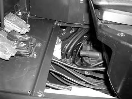
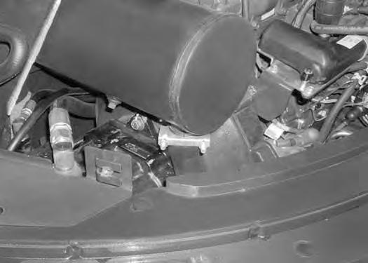
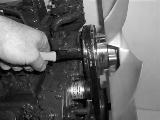
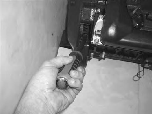
Figure218
NOTE:The engine is removed from the machine for photo clarity only. This procedure can be performed with engine installed in machine.
The engine will need to be rotated by hand to remove the belt. To access the flywheel, remove the plug (Item 1) [Figure218] from the flywheel housing.

Install
Continue to manually rotate the engine until the belt is off the
FAN BELT (CONT’D)
Belt Replacement (Cont’d)
Figure222
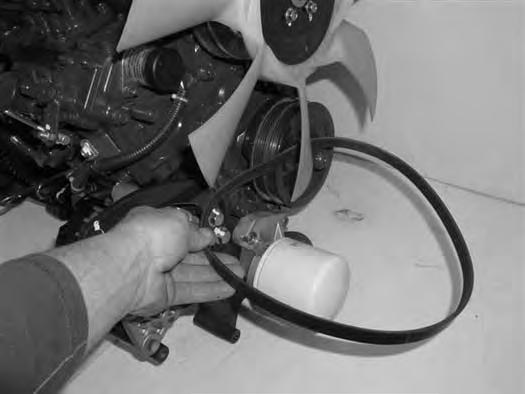
NOTE: Fan blades may be sharp, use care when removing the belt over the fan blades.
The belt (Item 1) [Figure222] will need to be worked over the fan blades until it can be removed.
Install the new fan belt.
Position the belt over the water pump pulley and next to the engine block and align the lower part of the belt to the crankshaft pulley.
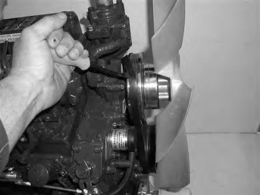
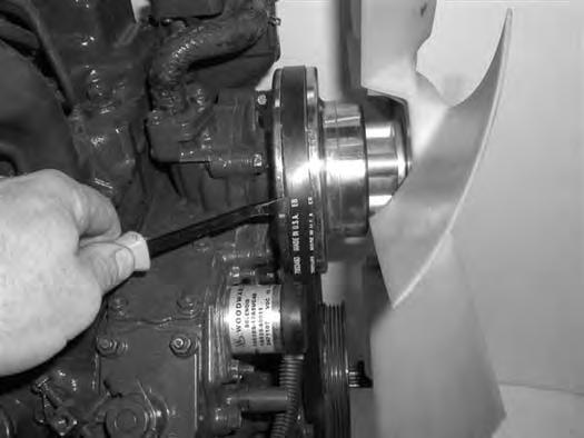
Using the pry bar (Item 1) [Figure219] to rotate the engine and push the belt on the pulley using the second pry bar (Item 1) [Figure223]
Continue rotating the engine until the belt is fully installed.
Install the flywheel plug (Item 1) [Figure218].
Install the alternator belt. (See ALTERNATOR BELT on Page142.)
Install the fan guard (Item 1) [Figure217]
Close the tailgate.
Quick Coupler
Quick Coupler And Attachment Inspection And Maintenance
Figure224
Inspect the quick coupler for wear or damage. Inspect the quick coupler pins (Item 1) and the hooks (Item 2) [Figure224] (on the attachment) for wear or damage
Repair or replace damaged parts.
X-CHANGE
Inspection And Maintenance
Figure225
Inspect the X-Change for wear or damage. Inspect the XChange pins (Item 1) and hooks (Item 2) [Figure225] (on the attachment) for wear or damage.
Repair or replace damaged parts.
Track Roller And Idler Lubrication
Procedure
The track rollers and idlers require no maintenance. The bearings are a sealed design.


Bucket Teeth Removal And Installation
Warning
Wear safety glasses to prevent eye injury when any of the following conditions exist:
•Pressurized fluids and springs or other stored energy components.
•Flying debris or loose material is present.
•Engine is running.
•Tools are being used.
W-2505-0604
Position the bucket so the bucket teeth are at a 30° angle up from the ground for accessibility to the teeth.
Lower the boom until the bucket is fully on the ground. Stop the engine and exit the excavator.
The retaining pin (Item 1) must be installed as shown [notch (Item 2) to the front] for proper fit and tooth retention. The side of the tooth point (Item 3) [Figure226] also shows the correct orientation of the retaining pin.
Installation: Position the new tooth point on the shank and install a new retaining pin. Install the retaining pin until it is flush with the top of the point.

LUBRICATION OF THE HYDRAULIC EXCAVATOR
Lubrication Locations
Lubricate the excavator as specified in the SERVICE SCHEDULE for the best performance of the machine. (See SERVICE SCHEDULE on Page 107.)
Always use a good quality lithium based multipurpose grease when lubricating the machine. Apply the lubricant until extra grease shows.

NOTE:Use Extra Heavy Gear Shield grease for grease fittings (Item 16, 17 and 18).
Lubricate the following locations on the excavator EVERY 8 - 10 HOURS:
LUBRICATION OF THE HYDRAULIC EXCAVATOR (CONT’D)
Lubrication Locations (Cont’d)
8.Arm Cylinder Base End (1) [Figure230]


(1) [Figure231]
LUBRICATION OF THE HYDRAULIC EXCAVATOR (CONT’D)
Lubrication Locations (Cont’d)
Figure234
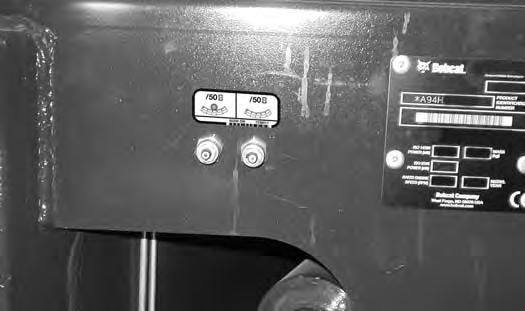
Lubricate the following locations on the hydraulic excavator EVERY 50 HOURS:
NOTE:Use Extra Heavy Gear Shield grease for grease fittings (Item 16, 17 and 18).
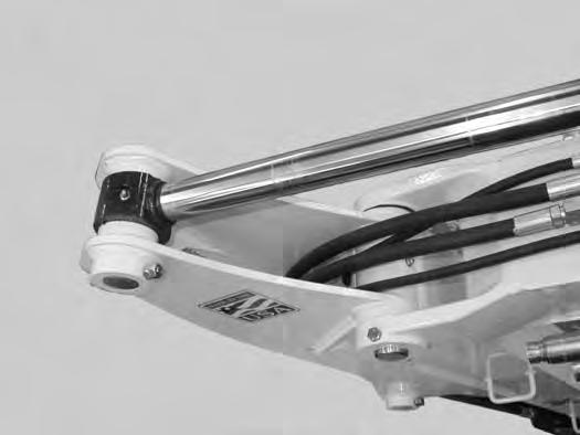
16.Swing Circle (1) [Figure234]
17.Swing Pinion (1) [Figure234]. (Install 3 to 4 pumps of grease then rotate the upperstructure 90°. Install 3 to 4 pumps of grease and again rotate the upperstructure 90°. Repeat this until the slew pinion has been greased at four positions.)
Lubricate the following location on the hydraulic excavator EVERY 1000 HOURS:
NOTE:Use Extra Heavy Gear Shield grease for grease fittings (Item 16, 17 and 18).
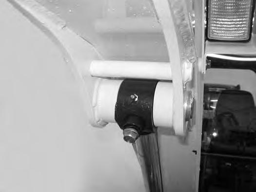
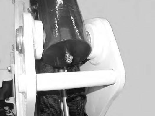
18.Boom Swing Cylinder Base (1) [Figure235]
NOTE:The boom swing grease fitting is located on the side of base end of the cylinder.