4 minute read
DISPLAY CONTROLLER PANEL SETUP


Passwords
All new machines with keyless option arrive at the Bobcat Dealerships with the panel in locked mode. This means that a password must be used to start the engine.
For security purposes, your dealer can change the password and also set it in the locked mode. Your dealer will provide you with the password.
Master Password: A permanent, randomly selected password is set at the factory which cannot be changed. This password is used for service by the Bobcat dealer if the Owner Password is not known; or to change the Owner Password.
Owner Password: There is only one Owner Password (CodE 0). It must be used to change the owner or operator passwords. See below for changing the Owner Password.
Operator Password: There can be up to three operator Passwords (CodE 1, CodE 2, CodE 3). See below for changing the Operator Password.
Password Entry (For Starting And Operating The Machine)
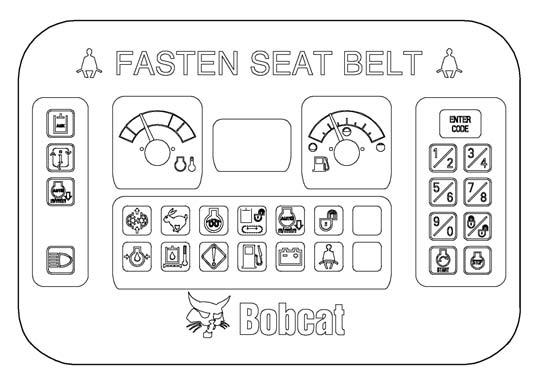
Press ENTER CODE button (Item 1). The panel will become lighted and there will be two short beeps. CodE will appear on the display screen (Item 2) [Figure225]
NOTE:After you press ENTER CODE you have 40 seconds to use the keypad (Item 3) [Figure225] to enter the password. (If more than 40 seconds is used, the process will abort and you will need to start over.
Enter the password. For each digit that you enter, a dash will appear on the display screen. If the password was entered correctly, there will be one long beep.
NOTE:If the password was incorrect there will be three short beeps and “Error” will appear on the display screen. Press the ENTER CODE button again and start over. After three failed attempts, you must wait three minutes to try again.
You are now ready to start and operate the machine.
If you will be changing the operator password, do not start the engine. (See Changing The Operator Password on Page 143.)
Changing The Operator Password
Figure225
Perform Password Entry at left, but do not start the engine.
Press and hold the ENTER CODE button (Item 1) for 3 seconds. CodE 1 will appear on the display screen (Item 2) [Figure225]
Press the ENTER CODE button until the desired Code (CodE 0, CodE 1, CodE 2, CodE 3) appears. CodE 0 is Owner Password, the other codes are Operator passwords.You now have 40 seconds to use the keypad (Item 3) [Figure225] to enter each digit of a new four digit password.
Enter the new four digit password. After the fourth digit is entered, there will be two short beeps and rPEAt will appear.
Re-enter the new four digit password to verify. If the new passwords match, there will be two short beeps, Code will appear for 1 second and then the display screen will return to HOURMETER function.
NOTE:If the new passwords do not match, there will be one long beep and “Error” will appear for 1 second and then the display screen will return to HOURMETER function.
DISPLAY CONTROLLER PANEL SETUP (CONT’D)
Password Lockout Feature
This allows the operator to Unlock the password feature so that a password does not need to be used every time you start the engine.
Perform Password Entry (See Password Entry (For Starting And Operating The Machine) on Page 143.) (the engine can be started or stopped.) The password entry can be performed with the engine off or with the engine running.
Figure226
Press the Lock / Unlock button (Item 1). The display screen (Item 5) [Figure226] will continuously alternate from UnLoc to CodE for 1 second periods.
Perform Password Entry again.
UnLoc will appear in the display screen (Item 5), the Unlocked Icon (Item 2) will appear in the Icon Display Area (Item 3) [Figure226] and there will be two short beeps.
To start an Unlocked system, press the ENTER CODE button and press the START button.
When you stop the engine with the system unlocked, you will hear one long beep every 3 seconds for 15 seconds.
To lock the system again, press the Lock / Unlock button (Item 1) [Figure226] and enter the password during the 15 second period.
Job Clock
The JOB CLOCK can be set to record accumulated hours for a particular job.
Press and release the information button (Item 4) until JOB light is ON at the top, centre of the display screen (Item 5) [Figure226]
While the JOB light is ON, press and hold the information button (Item 4) [Figure226] until the display screen returns to zero.
This process will clear the accumulated hours and will begin recording JOB CLOCK time again. (This does not affect the HOURMETER which continues to record the total operating hours of the excavator.)
Pressing the information button (Item 1) [Figure226] again or pressing the START button will return the display screen to HOURMETER function.
Rpm
The display screen (Item 5) [Figure226] can be set to display engine rpm.
With the engine running, press and release the information button (Item 4) until rpm light is ON at the top, centre of the display screen (Item 5) [Figure226].
Engine rpm is now displayed on the display screen.
Press the information button (Item 4) [Figure226] again the return to HOURMETER function.
Maintenance Clock
Description
The Maintenance Clock alerts the operator when the next service interval is due. EXAMPLE: The Maintenance Clock can be set to a 250 hour interval as a reminder for the next 250 hour planned maintenance.
During machine operation, a two beep alarm will sound when there are less than 10 hours until the next planned maintenance.
The hours interval (Item 1) and the [SEr] (Item 2) will alternate in the data display screen (Item 3) [Figure227] for 10 seconds.
The display will then revert back to the previous display and will appear for 10 seconds every time the machine is started until the maintenance clock is reset.
Setup
See your Bobcat dealer about installation of this feature.
To reset the panel after the scheduled maintenance is completed, do the following:
Turn the key switch to the OFF position or press the stop button (keyless panel).

Press the information button (Item 1) [Figure228] to turn the panel on.
Press and hold the information button (Item 1) and the auxiliary hydraulic button (Item 2) simultaneously until [rESEt] appears in the data display screen (Item 3) [Figure228]