28 minute read
MOTION ALARM SYSTEM Operation


Warning
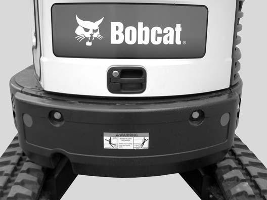
This machine is equipped with a motion alarm. ALARM MUST SOUND! when operating forward or backward.
Failure to maintain a clear view in the direction of travel could result in serious injury or death.
The operator is responsible for the safe operation of this machine.
W-2786-0309
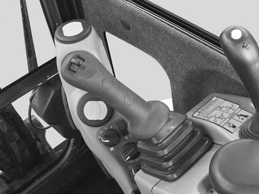
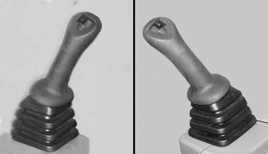
The motion alarm will sound when the operator moves the travel control levers (Item 1) [Figure36] in the either the forward or reverse direction.
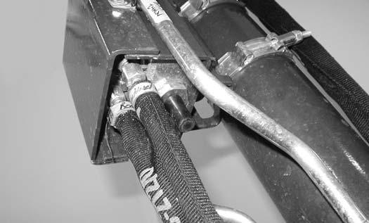
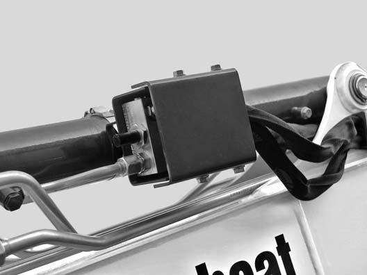
This excavator can be equipped with a motion alarm system. The motion alarm is located inside the rear (Item 1) [Figure34] of the excavator.
If alarm does not sound or for adjustment instructions, see inspection and maintenance instructions for the motion alarm system in the preventive maintenance section of this manual. (See MOTION ALARM SYSTEM on Page 102.)
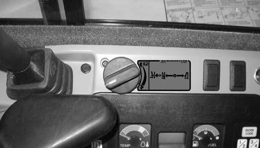
The motion alarm can be temporarily disabled by pressing the motion alarm switch (Item 1) [Figure35] while the machine is moving. As soon as the travel levers are returned to the neutral position, the motion alarm will be enabled.
Travel Controls
Forward And Reverse Travel
NOTE:The following procedures describe forward, reverse, left and right as seated in the operator’s seat.
Turning Right Turn
Figure37
Put the blade so that it is at the front of the machine (as you sit in the operator’s seat). Slowly move both steering levers* (Item 1) [Figure36] forward for forward travel; backward for reverse travel.

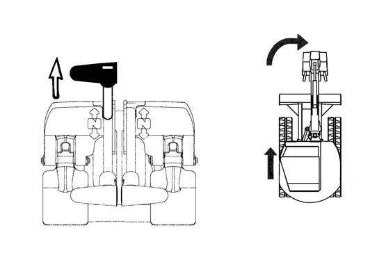
* Travel can also be controlled with foot pedals (Item 2) [Figure36]. Pivot the heel of the pedals forward for additional space on the floor.
Warning
AVOID INJURY OR DEATH
•Check the blade location before traveling. When the blade is to the rear, operate the steering levers/foot pedals in the opposite direction to when the blade is in the front.
•Move the steering levers/foot pedals slowly. Abrupt lever motion will cause the machine to jerk.

W-2235-0396
Push the left steering lever forward to turn right [Figure37] while travelling forward.
Pull the left steering lever backward to turn right while travelling backward [Figure38]
TRAVEL CONTROLS (CONT’D)
Turning (Cont’d)
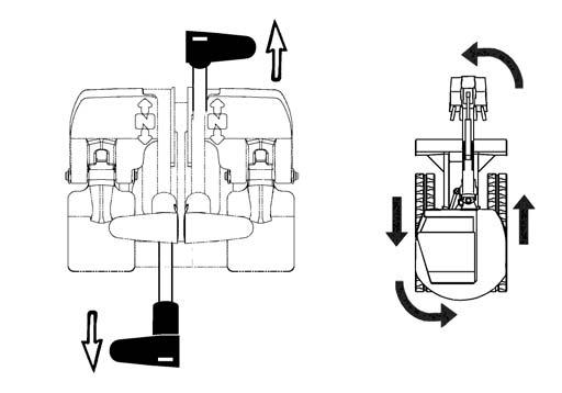
Counter-Rotation Right Turn
NA1459A
Push the left steering lever forward and pull the right steering lever backward [Figure39].


Left Turn
Push the right steering lever forward to turn left while travelling forward [Figure40]
Pull the right steering lever backward to turn left while travelling backward [Figure41]
Counter-Rotation Left Turn
Counter-Rotation (Left Turn)
Push the right steering lever forward and pull the left steering lever backward [Figure42]
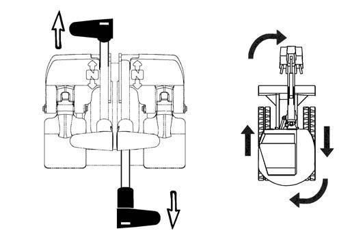
HYDRAULIC CONTROLS Description
The work equipment (boom, arm, bucket, and upperstructure slew) is operated by using the left and right control levers (joysticks).
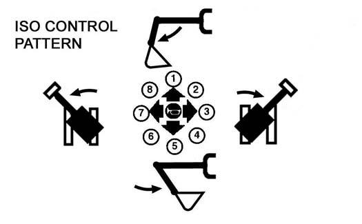
Left Control Lever (Joystick)
The left lever (joystick) is used to operate the boom and slew the upperstructure [Figure43]


1.Arm out.
2.Arm out and slew right.
3.Slew right.
4.Arm in and slew right.
5.Arm in.
6.Arm in and slew left.
7.Slew left.
8.Arm out and slew left.
Right Control Lever (Joystick)
Figure44
The right lever (joystick) is used to operate the arm and bucket [Figure44].
1.Boom lower.
2.Boom lower and bucket dump.
3.Bucket dump.
4.Boom raise and bucket dump.
5.Boom raise.
6.Boom raise and bucket curl.
7.Bucket curl.
8.Boom lower and bucket curl.
Warning
AVOID INJURY OR DEATH
Before leaving the machine:
•Lower the work equipment to the ground.
•Lower the blade to the ground.
•Stop the engine & remove the key.
•Raise the control console.
W-2780-0109
HYDRAULIC CONTROLS (CONT’D)
Quick Couplers
Warning
AVOID BURNS
Hydraulic fluid, tubes, fittings and quick couplers can get hot when running machine and attachments. Be careful when connecting and disconnecting quick couplers.
W-2220-0396
Warning
AVOID INJURY OR DEATH
Diesel fuel or hydraulic fluid under pressure can penetrate skin or eyes, causing serious injury or death. Fluid leaks under pressure may not be visible. Use a piece of cardboard or wood to find leaks. Do not use your bare hand. Wear safety goggles. If fluid enters skin or eyes, get immediate medical attention from a doctor familiar with this injury.
W-2072-EN-0909
To Connect:
Remove any dirt or debris from the surface of both the male and female couplers, and from the outside diameter of the male coupler. Visually check the couplers for corroding, cracking, damage, or excessive wear, if any of these conditions exist, the coupler(s) (Item 1) [Figure45] must be replaced.
Install the male coupler into the female coupler. Full connection is made when the ball release sleeve slides forward on the female coupler.
To Disconnect:
Excavators and attachments are supplied with flush faced couplers (Item 1) [Figure45]
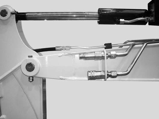
Hold the male coupler (Item 1). Retract the sleeve (Item 2) [Figure46] on the female coupler until the couplers disconnect.

HYDRAULIC CONTROLS (CONT’D)
Auxiliary Hydraulics
Figure47
Press the Auxiliary Hydraulics button on the right console (Item 1) [Figure47]
Relieve Hydraulic Pressure (Excavator And Attachment)
Excavator:
Put the attachment flat on the ground.
Stop the engine and turn the key switch to ON (Standard) or press ENTER CODE Button (Keyless).
NOTE:The left console must be fully lowered for relieving hydraulic pressure.
Press AUX HYD Button (Item 1) [Figure47] and then move the switch (Item 1) [Figure48] to the right and left several times.
Attachments:
•Follow procedure above to release pressure in excavator.
•Connect male coupler from attachment to female coupler of excavator then repeat procedure above. This will release pressure in the attachment.
•Connect the female coupler from the attachment.
Hydraulic pressure in the auxiliary hydraulic system can make it difficult to engage quick couplers to an attachment.
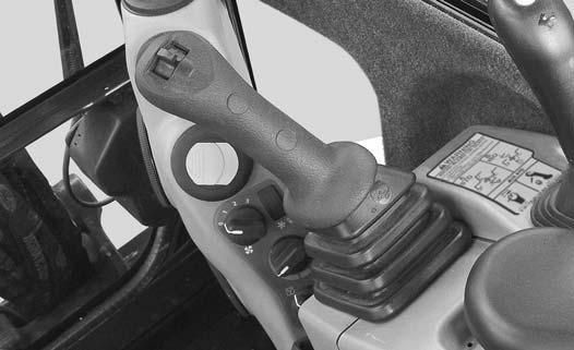
Move the switch (Item 1) [Figure48] on the right control lever to the right to supply hydraulic flow to the female coupler. Move the switch to the left to supply hydraulic flow to the male coupler. If you move the switch halfway, the auxiliary functions move at approximately one-half speed.
Press the switch (Item 2) [Figure48] on the front of the handle to provide constant flow to the female coupler.
NOTE:Pressing the switch (Item 1) to the left while pressing the switch (Item 2) [Figure48] on the front of the handle will provide constant flow to the male coupler.
Press the switch (Item 2) [Figure48] a second time to stop auxiliary flow to the quick couplers.
HYDRAULIC CONTROLS (CONT’D)
Secondary Auxiliary Hydraulics
When equipped with secondar y auxiliary hydraulics, the second set of hydraulic couplers will be mounted on the right side of the arm.
Relieve Hydraulic Pressure (Excavator And Attachment)
Excavator:
Put the attachment flat on the ground.
Stop the engine and turn the key switch to ON (Standard) or press ENTER CODE Button (Keyless).

NOTE:The left console must be fully lowered for relieving hydraulic pressure.
Move the boom swing / secondary auxiliary hydraulic switch (Item 1) [Figure49] to the right, secondary auxiliary hydraulic position.
Move the switch (Item 1) [Figure50] to the right and left several times.
Attachments:
•Follow procedure above to release pressure in excavator.
Move the boom swing / secondary auxiliary hydraulic switch (Item 1) [Figure49] to the right, secondary auxiliary hydraulic position.
•Connect male coupler from attachment to female coupler of excavator then repeat procedure above. This will release pressure in the attachment.
•Connect the female coupler from the attachment.
Hydraulic pressure in the auxiliary hydraulic system can make it difficult to engage quick couplers to an attachment.
Move the switch (Item 1) [Figure50] on the left control lever to the left to supply hydraulic flow to the female coupler. Move the switch to the right to supply hydraulic flow to the male coupler. If you move the switch halfway, the auxiliary functions move at approximately one-half speed.
HYDRAULIC CONTROLS (CONT’D)
Direct To Tank Valve
The direct to tank valve (if equipped) is located under the cab floor.
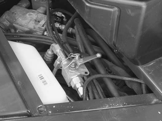
Remove the floor mat and floor panel. (See the Service Manual for the correct procedure.)
Rotate the lever (Item 1) [Figure51] clockwise to direct auxiliary return flow to the hydraulic fluid reservoir.
Rotate the lever (Item 1) [Figure51] anticlockwise for two way hydraulic auxiliary flow operation.
Blade Control Lever
Raising And Lowering Blade
Figure52
Pull the lever backward to raise the blade (Item 1) [Figure52]
Push the lever forward to lower the blade (Item 2) [Figure52]
NOTE:Keep blade lowered for increased digging performance.
Engine Speed Control
Setting Engine Speed (RPM)
Engine Speed Control Lever (If Equipped)

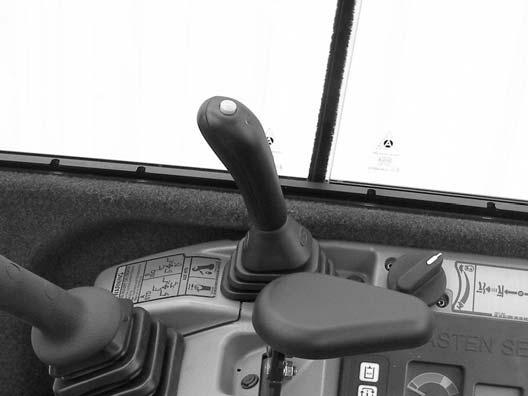
Figure53
The engine speed control lever (Item 1) [Figure53] controls engine rpm.
Pull the engine speed control lever back (Item 2) to reduce engine rpm. Push the engine speed control lever forward (Item 3) [Figure53] to increase engine rpm.
Engine Speed Control Dial (If Equipped)
Figure54
The engine speed control dial (Item 1) [Figure54] controls engine rpm.
Rotate the engine speed control dial anticlockwise (Item 2) to reduce engine rpm. Rotate the engine speed control dial clockwise (Item 3) [Figure54] to increase engine rpm.

The switch (Item 1) [Figure55] on the left control lever (joystick) controls boom swing. Move the switch to the left to swing the boom to the left. Move the switch to the right to swing the boom to the right.

With Secondary Auxiliary Hydraulics:
If the machine is equipped with secondary auxiliary hydraulic couplers, the switch (Item 2) [Figure55] is used to select either the boom swing function or the secondary auxiliary hydraulic function.
Move the switch (Item 2) [Figure55] to the left to select boom swing function, move the switch to the right to select secondary auxiliary hydraulic function.
NOTE:The purpose of the boom swing is to offset the boom with respect to the upperstructure for digging close to a structure [Figure56].

BOOM LOAD HOLDING VALVE
Description
The boom load holding valve (if equipped) will hold the boom in it’s current position in the event of hydraulic pressure loss.
Warning
AVOID INJURY OR DEATH
Do Not work or stand under raised work equipment or attachment.
W-2793-0409
Warning
AVOID BURNS
Hydraulic fluid, tubes, fittings and quick couplers can get hot when running machine and attachments. Be careful when connecting and disconnecting quick couplers.
If the excavator is equipped with a boom load holding valve (Item 1) [Figure57], it will be attached to the boom cylinder at the base end.

NOTE:DO NOT remove or adjust the two port relief valves (Item 2) [Figure57]. If the port relief valves have been tampered with, see your Bobcat dealer for service.
BOOM LOAD HOLDING VALVE (CONT’D)
Lowering Boom With Load Holding Valve (Cont’d)
Figure59
Lowering procedures:
With base end hose failure:
Loosen the jam nut (Item 1). Install a hex wrench into the valve screw (Item 2) [Figure59] and slowly rotate the screw clockwise 45° to 90° turn and allow the boom to lower to the ground.
After the boom is fully lowered, rotate the screw anticlockwise (Item 2) 45° to 90° turn and tighten the lock nut (Item 1) [Figure59].
With rod end hose failure - with accumulator pressure:
Place a container under the valve and hose end to contain hydraulic fluid. Enter the excavator and turn the key switch to the ON position or press the ENTER CODE Button (Keyless Panel), but do not start the engine. Slowly move the joystick boom lower function and allow the boom to lower to the ground.
With rod end hose failure and NO accumulator pressure:
Remove the boom base end hose from the boom load holding valve. Place a container under the valve and base end hose to contain hydraulic fluid.
Loosen the jam nut (Item 1). Install a hex wrench into the valve screw (Item 2) [Figure59] and slowly rotate the screw clockwise 45° to 90° turn and allow the boom to lower to the ground.
After the boom is fully lowered, rotate the screw (Item 2) anticlockwise 45° to 90° turn and tighten the lock nut (Item 1) [Figure59]. Reinstall the base end hose.
Loss of hydraulic pressure:
Use the same procedure as: With rod end hose failure and NO accumulator pressure

ARM LOAD HOLDING VALVE
Description
The arm load holding valve (if equipped) will hold the arm in it’s current position in the event of hydraulic pressure loss.
Warning
AVOID INJURY OR DEATH
Do Not work or stand under raised work equipment or attachment.
W-2793-0409
NOTE:DO NOT remove or adjust the two port relief valves (Item 1) [Figure61]. If the port relief valves have been tampered with, see your Bobcat dealer for service.

If the excavator is equipped with arm load holding valve (Item 1) [Figure60], it will be attached to the arm cylinder base end as shown.

Warning
AVOID BURNS
Hydraulic fluid, tubes, fittings and quick couplers can get hot when running machine and attachments. Be careful when connecting and disconnecting quick couplers.
W-2220-0396
ARM LOAD HOLDING VALVE (CONT’D)
Lowering Arm With Load Holding Valve (Cont’d)
Figure63
Lowering procedures:
With base end hose failure:
Loosen the jam nut (Item 1). Install a hex wrench into the valve screw (Item 2) [Figure63] and slowly rotate the screw clockwise 45° to 90° turn and allow the arm to lower.
After the arm is lowered, rotate the screw anticlockwise (Item 2) the same 45° to 90° turn and tighten the lock nut (Item 1) [Figure63].
With rod end hose failure - with accumulator pressure:

Place a container under the valve and hose end to contain hydraulic fluid. Enter the excavator and turn the key switch to the ON position or press the ENTER CODE Button (Keyless Panel), but do not start the engine. Move the joystick arm retract function to slowly lower the arm.
With rod end hose failure and NO accumulator pressure:
Remove the arm base end hose from the arm load holding valve. Place a container under the valve and base end hose to contain hydraulic fluid.
Loosen the jam nut (Item 1). Install a hex wrench into the valve screw (Item 2) [Figure63] and slowly rotate the screw clockwise 45° to 90° turn and allow the arm to lower.
After the arm is lowered, rotate the screw (Item 2) anticlockwise 45° to 90° turn and tighten the lock nut (Item 1) [Figure63]. Reinstall the base end hose.
Loss of hydraulic pressure:
Use the same procedure as: With rod end hose failurewith NO accumulator pressure above.
Daily Inspection
Daily Inspection And Maintenance
Figure64
Warning
Operator must have instructions before operating the machine. Untrained operators can cause injury or death.
W-2001-0502
Fluids such as engine oil, hydraulic fluid, coolants, etc. must be disposed of in an environmentally safe manner. Some regulations require that certain spills and leaks on the ground must be cleaned in a specific manner. See local regulations for correct disposal.
Important
Pressure Washing Decals
Maintenance work must be done at regular intervals. Failure to do so will result in excessive wear and early failures. The service schedule is a guide for correct maintenance of the Bobcat excavator. The decal (Item 1) [Figure64] is located on the inside of the tailgate58

.
(See SERVICE SCHEDULE on Page 99.)
Check the following items before each day of operation:
•Operator Canopy or Cab (ROPS / TOPS) and mounting hardware.
•Seat belt and mounting hardware. Replace seat belt if damaged.
•Check for damaged decals, replace as needed.
•Check control console lockout.
•Check X-Change System (if equipped) for damage or loose parts.
•Air cleaner and intake hoses / clamps.
•Engine oil level and engine for leaks.
•Engine coolant level and engine for leaks.
•Check engine area for flammable materials.
•Check hydraulic fluid level and system for leaks.
•Check indicator lights for correct operation.
•Grease all pivot points.
•Check cylinder and attachment pivot points.
•Check the track tension.
•Repair broken and loose parts.
•Clean cab heater filter (if equipped).
•Check front horn and motion alarm (if equipped) for proper function.
•Never direct the stream at a low angle toward the decal that could damage the decal causing it to peel from the surface.
•Direct the stream at a 90 degree angle and at least 300 mm (12 in) from the decal. Wash from the centre of the decal toward the edges.
I-2226-EN-0910
Important
This machine is factory equipped with a spark arrester exhaust system.
The spark arrester muffler, if equipped, must be cleaned to keep it in working condition. The spark arrester muffler must be serviced by dumping the spark chamber every 100 hours of operation.
On some models, the turbocharger functions as the spark arrester and must operate correctly for proper spark arrester function.
If this machine is operated on flammable forest, brush, or grass covered land, a spark arrester attached to the exhaust system may be required and must be maintained in working order. Refer to local laws and regulations for spark arrester requirements.
I-2284-EN-0909
PRE-STARTING PROCEDURE
Operation & Maintenance Manual And Operator’s Handbook Locations
Entering The Excavator
Warning
AVOID INJURY OR DEATH
Instructions are necessary before operating or servicing machine. Read and understand the Operation & Maintenance Manual, Operator’s Handbook and signs (decals) on machine. Follow warnings and instructions in the manuals when making repairs, adjustments or servicing. Check for correct function after adjustments, repairs or service. Untrained operators and failure to follow instructions can cause injury or death.
Read and understand the Operation & Maintenance Manual (Item 1) [Figure65] (located inside the storage box on the back of the operator’s seat) and the Operator’s Handbook (Item 1) [Figure66] before operating.


PRE-STARTING PROCEDURE (CONT’D)
Seat Adjustment
Standard Seat
Figure68
Release the seat lever (Item 1) [Figure68] to adjust the seat forward or back.
Sit in the seat and turn the knob (Item 2) [Figure68] to adjust the position of the back cushion.

Suspension Seat (If Equipped)


Figure69
Release the seat lever (Item 1) [Figure69] to adjust the seat forward or back.
Turn the handle (Item 2) to change the adjustment for operator weight. Turn the handle until the operator’s weight is shown in the window (Item 3) [Figure69]
Release the lever (Item 4) [Figure69] to adjust the position of the back cushion.
Sit in the seat and turn the knob (Item 5) [Figure69] to adjust the height of the seat.
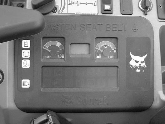
Seat Belt
Figure70
PRE-STARTING PROCEDURE (CONT’D)
Control Console
Figure71
NOTE:There is a control lock sensor in the left console which deactivates the hydraulic control levers (joysticks) and the traction drive system when the control console is raised. The console must be in the locked down position for the hydraulic control levers (joysticks) and traction system to operate.

NOTE:If the control lock sensor does not deactivate the control levers and traction system when console is raised, see your Bobcat dealer for service.
Mirror Adjustment
Figure72

STARTING THE ENGINE
Key Switch
Warning
AVOID INJURY OR DEATH
•Fasten seat belt, start and operate only from the operator’s seat.

•Never wear loose clothing when working near machine.
W-2135-1108
Perform the PRE-STARTING PROCEDURE. (See PRESTARTING PROCEDURE on Page 63.)
STARTING THE ENGINE (CONT’D)
Key Switch (Cont’d)
Figure76
Warning
AVOID INJURY OR DEATH
When an engine is running in an enclosed area, fresh air must be added to avoid concentration of exhaust fumes. If the engine is stationary, vent the exhaust outside. Exhaust fumes contain odorless, invisible gases which can kill without warning.
W-2050-0807 S39309
Turn the key switch (Item 1) [Figure76] to the ON position. If preheating is required, the glow plugs will automatically cycle and the remaining preheat time (in seconds) will show in the data display screen. (Preheat icon will be ON).
Turn the key switch to START and release the key switch when the engine starts. It will return to the ON position [Figure76]

Important
Do not engage the starter for longer than 15 seconds at a time. Longer use can damage the starter by overheating. Allow starter to cool for one minute before using starter again.
I-2034-0700
Stop the engine if the warning lights and alarm do not go OFF. Check for the cause before starting the engine again.
Turn the key switch OFF to stop the engine.
Warning
AVOID SERIOUS INJURY OR DEATH
•Engines can have hot parts and hot exhaust gas. Keep flammable material away.
•Do not use machines in atmosphere containing explosive dust or gases.
W-2051-0212
STARTING THE ENGINE (CONT’D)
Keyless
Warning
AVOID INJURY OR DEATH
•Fasten seat belt, start and operate only from the operator’s seat.

•Never wear loose clothing when working near machine.
W-2135-1108
Perform the PRE-STARTING PROCEDURE. (See PRESTARTING PROCEDURE on Page 63.)
Press ENTER CODE Button (Item 1) [Figure79]. The display will become lighted and there will be two short beeps, “CodE” will appear on the display screen.
Use the keypad (Item 2) [Figure79] to enter the password. For each digit that you enter, a dash will appear on the data display screen. (You have 40 seconds to enter the password or the process will abort and you will need to start over.) If the password was entered correctly, there will be one long beep.
NOTE:If the password was incorrect there will be three short beeps and “Error” will appear on the data display screen. Press the ENTER CODE Button again and start over. After three failed attempts, you must wait 3 minutes to try again.
Press the START Button (Item 3) [Figure79] and hold it until the engine starts.
Pull the engine speed control lever (Item 1) [Figure77] back to low idle.
Important
Do not engage the starter for longer than 15 seconds at a time. Longer use can damage the starter by overheating. Allow starter to cool for one minute before using starter again.
I-2034-0700
Warning
AVOID SERIOUS INJURY OR DEATH
•Engines can have hot parts and hot exhaust gas. Keep flammable material away.
Rotate the engine speed control dial (if equipped) (Item 1) [Figure78] anticlockwise to low idle.
•Do not use machines in atmosphere containing explosive dust or gases.
W-2051-0212
STARTING THE ENGINE (CONT’D)
Keyless (Cont’d)
Press the STOP button (Item 4) [Figure79] to stop the engine.
Stop the engine if the warning lights and alarm do not go OFF.
Check for the cause before starting the engine again.
Password Lockout Feature
See Password Lockout Feature. (See Password Lockout Feature on Page 144.)
Warning
AVOID INJURY OR DEATH
When an engine is running in an enclosed area, fresh air must be added to avoid concentration of exhaust fumes. If the engine is stationary, vent the exhaust outside. Exhaust fumes contain odorless, invisible gases which can kill without warning.
W-2050-0807
STARTING THE ENGINE (CONT’D)
Cold Temperature Starting
Warning
AVOID INJURY OR DEATH
Do not use ether with glow plug (preheat) systems. Explosion can result which can cause injury, death, or severe engine damage.
W-2071-0907
If the temperature is below freezing, perform the following to make starting the engine easier:
•Replace the engine oil with the correct type and viscosity for the anticipated starting temperature. (See Engine Oil Charton page113.)
•Make sure the battery is fully charged.
•Install an engine heater.
NOTE:If the battery is discharged (but not frozen) a booster battery can be used to jump start the excavator. (See Using A Booster Battery (Jump Starting)on page121.)
Important
Do not engage the starter for longer than 15 seconds at a time. Longer use can damage the starter by overheating. Allow starter to cool for one minute before using starter again.
STARTING THE ENGINE (CONT’D)
Cold Temperature Starting Procedure (Cont’d)
Key Switch
Figure82
Keyless
Follow STARTING PROCEDURE (See Keyless on Page 68.)
If the preheat icon comes ON, wait for it to go off before pressing the START Button [Figure83].
The remaining preheat time (in seconds) will count down in the data display screen.
Important
Do not engage the starter for longer than 15 seconds at a time. Longer use can damage the starter by overheating. Allow starter to cool for one minute before using starter again.
I-2034-0700
Turn the key switch to the ON position [Figure82]
Figure83
Important
Machines warmed up with moderate engine speed and light load have longer life.
I-2015-0284
Warning
AVOID INJURY OR DEATH
Do not use ether with glow plug (preheat) systems. Explosion can result which can cause injury, death, or severe engine damage.
W-2071-0907
The preheat icon (Item 1) [Figure83] will illuminate. The glow plugs will automatically cycle. When the icon goes off, turn the key switch to start.
Release the key switch when the engine starts, it will return to the ON position.
Stop the engine if the warning lights and alarm do not go off. Check for the cause before starting the engine again.
When the engine speed increases, move the engine speed control to idle position until the engine warms.
Important
When the temperature is below -30°C (-20°F), hydrostatic oil must be warmed before starting. The hydrostatic system will not get enough oil at low temperatures and will be damaged. Park the machine in an area where the temperature will be above -18°C (0°F) if possible.
I-2007-0910
Let the engine run at least 5 minutes to warm the engine and hydraulic fluid before operating the excavator.
STOPPING THE ENGINE AND LEAVING THE EXCAVATOR
Procedure
Figure84
Stop the machine on level ground. Lower the work equipment and the blade to the ground [Figure84]

Run the engine at idle speed for about 5 minutes to allow it to cool.
Pull the engine speed control lever (Item 1) [Figure85] back to low idle.
Turn the key switch to STOP [Figure87] or press the STOP Button (Keyless Panel) (Item 1) [Figure88]
Disconnect the seat belt. Remove the key (if equipped) from the switch to prevent operation of machine by unauthorised personnel. Raise the control console and exit the machine.

Rotate the engine speed control dial (if equipped) (Item 1) [Figure86] anticlockwise to low idle.
Attachments
Installing And Removing The Attachment (Pin-On Attachment)
Installation
Warning
AVOID INJURY OR DEATH
Stop the machine on a firm flat surface. When removing or installing attachments (such as a bucket), always have a second person in the operator’s seat, give clear signals and work carefully.
W-2140-0189
Install the two retainer pins (Item 1) [Figure90]. Install grease in the grease fittings.
Removal
Park the excavator on a flat surface and lower the bucket fully.
Remove the two retainer pins (Item 1) [Figure90]
Remove the washers and pins (Items 1 and 3) [Figure89].
Do not damage the dust seals in the arm.
Warning
Install the arm into the bucket and align the mounting hole.
Install the pin (Item 1) [Figure89] and washers.
Install the link (Item 2) in the bucket and align the mounting hole. Install the pin (Item 3) [Figure89] and washers.

AVOID INJURY OR DEATH
Never use attachments or buckets which are not approved by Bobcat Company. Buckets and attachments for safe loads of specified densities are approved for each model. Unapproved attachments can cause injury or death.
W-2052-0907
ATTACHMENTS (CONT’D)
Installing And Removing The Attachment (Quick Coupler, Klac™ System)
Installation
NOTE: Installation and removal of the bucket is shown. The procedure is the same for other attachments. Disconnect any hydraulic lines that are operated by hydraulic power before removing any attachments (breaker, auger etc.).
Warning
AVOID INJURY OR DEATH
Never use attachments or buckets which are not approved by Bobcat Company. Buckets and attachments for safe loads of specified densities are approved for each model. Unapproved attachments can cause injury or death.
Warning
Avoid Injury
Keep fingers and hands out of pinch points when latching and unlatching the attachment quick coupler.
Fully retract the bucket cylinder.
Stop the engine and exit the excavator.
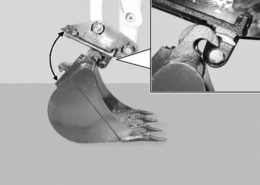
Inspect the quick coupler to make sure the latch is in the unlatched position (Item 1) [Figure91]

If in the latched position, see [Figure92] for additional information.
If the latch is in the unlatched position, proceed to [Figure93].
To unlatch the quick coupler, install the tool (Item 1) [Figure92] and pull the handle. The latch will move completely forward. The latch will lock in the unlatched position.
Enter the excavator, fasten the seat belt and start the engine.
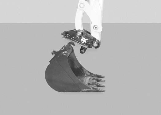
Position the quick coupler (Item 1) to the attachment (Item 2) [Figure93]
ATTACHMENTS (CONT’D)
Installing And Removing The Attachment (Quick Coupler, Klac™ System) (Cont’d)
Installation (Cont’d)
Figure94
There must be at least 100 between the quick coupler surface (Item 1) and the attachment mounting surface (Item 2) [Figure94]. Extend the arm out to get the required angle for proper installation.

NOTE: There must be proper clearance (100 minimum) between the hook (Item 3) and the quick coupler (Item 4) [Figure94]. Possible damage to the attachment hooks or the quick coupler could occur without proper clearance.
Raise the boom until there is approximately 500 mm (20.0 in) of clearance between the bottom of the attachment and the ground [Figure96]
Raise the boom and extend the arm until the hooks of the attachment (Item 1) engage the pins (Item 2) of the quick coupler [Figure95].
Extend the bucket cylinder (Item 1) [Figure97] fully.
Lower the attachment until it is flat on the ground.
Stop the engine and exit the excavator.
ATTACHMENTS (CONT’D)
Installing And Removing The Attachment (Quick Coupler, Klac™ System) (Cont’d)
Installation (Cont’d)
Figure98
Figure99
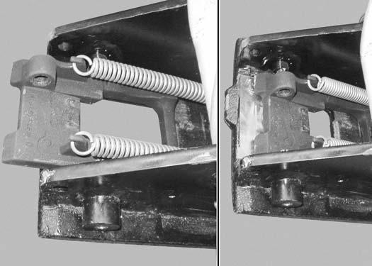
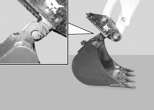
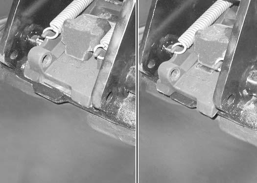
Visually inspect the quick coupler latch (Item 1) to the bucket mount (Item 2) [Figure98]. The latch must be fully engaged.

Warning
AVOID INJURY
Keep fingers and hands out of pinch points when latching and unlatching the attachment quick coupler.
W-2541-1106
If the latch is not engaged, install the tool (Item 1) in the hole (Item 2) [Figure99] of the quick coupler and push down to unlatch the quick coupler. Remove the tool. Enter the excavator, fasten the seat belt and start the engine. Raise the attachment 500 mm (20.0 in) off of the ground and fully extend the bucket cylinder. Lower the attachment until it is flat on the ground. Engage the parking brake. Stop the engine and exit the excavator.
Again, visually inspect the quick coupler to make sure the latch (Item 1) [Figure98] is fully engaged. If it is not fully engaged, remove the attachment and inspect both the quick coupler and the attachment for damage or debris. (See [Figure103] for Quick Coupler And Attachment Inspection information.)
ATTACHMENTS (CONT’D)
Installing And Removing The Attachment (Quick Coupler, Klac™ System) (Cont’d)
Removal
Warning
AVOID INJURY
Keep fingers and hands out of pinch points when latching and unlatching the attachment quick coupler.
W-2541-1106
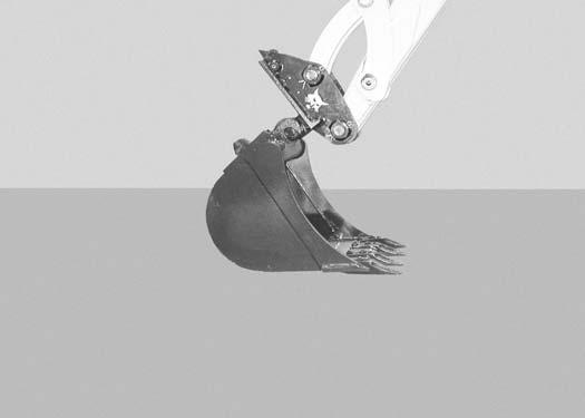
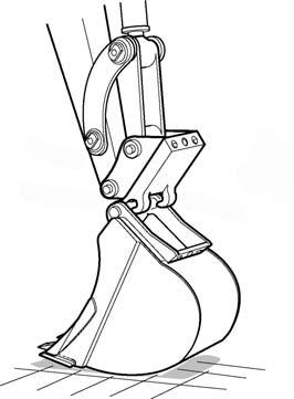
Retract the bucket cylinder fully and lower the boom [Figure101] until the attachment is on the ground.
Position the attachment flat on the ground.
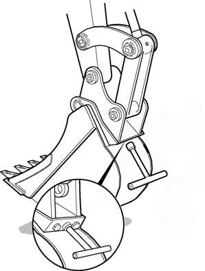
Install the quick coupler tool (Item 1) into the hole (Item 2) [Figure99] in the quick coupler.
Push down on the tool (Item 1) [Figure100] to unlock the latch.
Remove the tool.
Enter the excavator, fasten the seat belt and start the engine.
Continue to lower the boom and move the arm toward the excavator until the quick coupler is clear of the attachment [Figure102].


ATTACHMENTS (CONT’D)
Installing And Removing The Attachment (Quick Coupler, Klac™ System) (Cont’d)
Quick Coupler And Attachment Inspection
Figure103
Inspect the quick coupler for wear or damage. Inspect the quick coupler pins (Item 1) and the hooks (Item 2) [Figure103] (on the attachment) for wear or damage.
Repair or replace damaged parts.
ATTACHMENTS (CONT’D)
Installing And Removing The Attachment (Quick Coupler, Lehnhoff® System)
Installation
NOTE: Installation and removal of the bucket is shown. The procedure is the same for other attachments. Disconnect any hydraulic lines that are operated by hydraulic power before removing any attachments (breaker, auger etc.).
Warning
AVOID INJURY OR DEATH
Never use attachments or buckets which are not approved by Bobcat Company. Buckets and attachments for safe loads of specified densities are approved for each model. Unapproved attachments can cause injury or death.
W-2052-0907
Enter the excavator. (See Entering The Excavator on Page 63.)
Position the excavator so the excavator arm is above the attachment.
Fully retract the bucket cylinder.
Lower the coupler (Item 1) onto the attachment (Item 2) [Figure104].
Engage the coupler hooks (Item 1) onto the attachment shaft (Item 2) [Figure105]
Extend (curl in) the bucket cylinder and slightly raise the boom until the coupler (Item 1) contacts the back of the attachment mount (Item 2) [Figure106].


Engage the parking brake.
Stop the engine and exit the excavator.
ATTACHMENTS (CONT’D)
Installing And Removing The Attachment ((Quick Coupler, Lehnhoff® System) (Cont’d)
Installation (Cont’d)
Use the supplied tool (Item 1) or (Item 2) [Figure107] and turn the locking pins clockwise until they are fully engaged.
Removal Park the excavator on a level surface.
Install the tool (Item 1) or (Item 2) [Figure109] on the locking pins and turn anticlockwise until the locking pins are disengaged.
Raise the boom and extend the bucket cylinder until the attachment it is slightly off the ground [Figure108]
Engage the parking brake.
Stop the engine and exit the excavator.
Enter the excavator, fasten the seat belt and start the engine
Lower the attachment until it is on the ground [Figure110]


ATTACHMENTS (CONT’D)
Installing And Removing The Attachment (Quick Coupler, Lehnhoff® System) (Cont’d)
Removal (Cont’d)
Figure111
S3022A
Retract the bucket cylinder to rotate the coupler (Item 1) out of the attachment mount (Item 2) [Figure111]
Figure112
S3023A
Move the arm out and raise the boom until the quick coupler is clear of the attachment [Figure112]

Quick Coupler And Attachment Inspection
Figure113
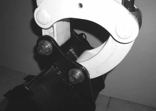
The locking pins must contact the lower edge of the attachment mounting frame.
The locking pins (Item 1) [Figure113] must extend through the holes in the attachment mounting frame, securely fastening the attachment to the coupler.

If both locking pins do not engage in the locked position, see your bobcat dealer for service.
Inspect the quick coupler for wear or damage. Inspect the attachment shaft and the quick coupler hooks for wear or damage.
Repair or replace damaged parts.
OPERATING PROCEDURE Inspect The Work Area
Before beginning operation, inspect the work area for unsafe conditions.
Look for sharp drop-offs or rough terrain. Have underground utility lines (gas, water, sewer, irrigation, etc.) located and marked. Work slowly in areas of underground utilities.
Remove objects or other construction material that could damage the excavator or cause personal injury.
Always check ground conditions before starting your work:
•Inspect for signs of instability such as cracks or settlement.
•Be aware of weather conditions that can affect ground stability.
•Check for adequate traction if working on a slope.
Basic Operating Instructions
When operating on a public road or motorway, always follow local regulations. For example: A slow moving vehicle (SMV) sign, or direction signals can be required.
Run the engine at low idle speed to warm the engine and hydraulic system before operating the excavator.
Important
Machines warmed up with moderate engine speed and light load have longer life.
I-2015-0284
New operators must operate the excavator in an open area without bystanders. Operate the controls until the excavator can be handled at an efficient and safe rate for all conditions of the work area.
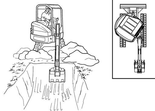
Operating Near An Edge Or Water
Keep the excavator as far back from the edge as possible and the excavator tracks perpendicular to the edge so that if part of the edge collapses, the excavator can be moved back.
Always move the excavator back at any indication the edge can be unstable.
Lowering The Work Equipment (Engine STOPPED)
The hydraulic control levers control the movement of the boom, arm, bucket and upperstructure slew functions.
The console must be in the locked down position, and the key switch in the ON position.
Use the control lever to lower the boom.
The joystick lock switch disengages the hydraulic control functions from the joysticks when the console are raised [Figure114]
NOTE:If the engine stops, the boom / bucket (attachments) can be lowered to the ground using hydraulic pressure in the accumulator.
The control console must be in the locked down position, and the key switch in the ON position.
Use the control lever to lower the boom.
Lower the control console to engage the hydraulic control functions of the joysticks [Figure114]
OPERATING PROCEDURE (CONT’D)
Using The Clamp
Figure115
The optional lifting clamp attachment gives the excavator a wider range of use and mobility for debris removal [Figure115]

The lifting clamp cylinder must be fully retracted when the machine is being used for excavating.
The lift capacities are reduced by 122 kg (270 lb) if the excavator is equipped with the optional lifting clamp.
When Using Primary Auxiliary Hydraulics To Activate Clamp
Engage auxiliary hydraulics. (See Auxiliary Hydraulics on Page 53.)
Figure116
Move the switch (Item 1) [Figure116] on the right control lever to the left to open the clamp. Move the switch to the right to close the clamp.
When Using Secondary Auxiliary Hydraulics To Activate Clamp
Engage secondary auxiliary hydraulics. (See Secondary Auxiliary Hydraulics on Page 54.)
Move the switch (Item 2) [Figure116] on the left control lever to the right open the clamp. Move the switch to the left to close the clamp.
OPERATING PROCEDURE (CONT’D)
Excavating
Lower the blade to increase digging performance.
Figure117
Extend the arm, lower the boom, and open the bucket [Figure117].
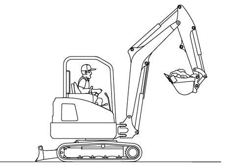

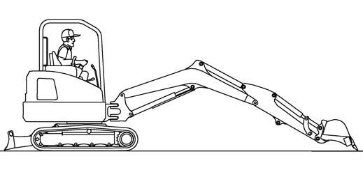
Figure118
Retract the arm, while lowering boom and curling the bucket [Figure118]
Figure119
Raise the boom, retract the arm and curl the bucket [Figure119]
Rotate the upperstructure.
NOTE:Do not allow the bucket teeth to contact the ground when slewing the upperstructure.
Warning
Keep all bystanders 6 m (20 ft) away from equipment when operating. Contact with moving parts, a trench cave-in or flying objects can cause injury or death.
W-2119-0910
Warning
AVOID INJURY OR DEATH
Check area to be excavated for overhead or underground electrical power lines. Keep a safe distance from electrical power lines.
W-2757-0910
OPERATING PROCEDURE (CONT’D)
Excavating (Cont’d)
Figure120
Look in the direction of rotation and make sure there are no bystanders in the work area before rotating the upperstructure [Figure120]
Do not dig under the excavator [Figure122].

Do not use the bucket as a breaker or pile driver. It is better to excavate hard or rocky ground after breaking it with other equipment. This will reduce damage to the excavator.
Do not move the excavator while the bucket is in the ground.
Dig only by moving the boom and arm toward the excavator.
Do not back dig (digging by moving the boom and arm away from the excavator). Damage to the quick coupler and attachments can occur.

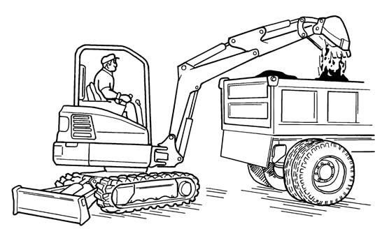
Extend the arm and uncurl the bucket to dump the material into a pile or truck [Figure121]
Important
Avoid operating hydraulics over relief pressure. Failure to do so will overheat hydraulic components. I-2220-0503
OPERATING PROCEDURE (CONT’D)
Boom Swing
Slew the upperstructure, swing the boom to the right [Figure123], centre [Figure124] and left [Figure125] to dig a square hole the width of the machine without repositioning the excavator.

The boom swing allows the operator to offset the boom and dig close to buildings and other structures [Figure126]

OPERATING PROCEDURE (CONT’D)
Backfilling
Important
Avoid impacting objects with the blade. Damage to blade and undercarriage components may occur.
I-2256-0507
Driving The Excavator
When operating on uneven ground, operate as slow as possible and avoid sudden changes in direction.
Avoid travelling over objects such as rocks, trees, stumps, etc.
When working on wet or soft ground, put planks on the ground to provide a solid base to travel on and prevent the excavator from getting stuck.
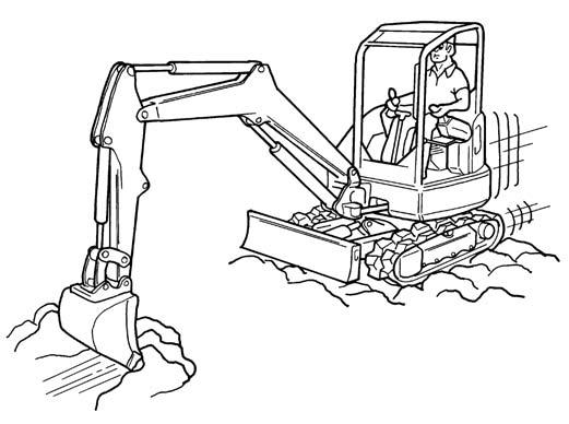
Use the blade to backfill the trench or hole after excavating [Figure127]
If one or both tracks have become stuck in soft or wet ground, raise one track at a time by turning the upperstructure and pushing the bucket against the ground [Figure128]
Put planks under the tracks and drive the excavator to dry ground.
The bucket can also be used to pull the excavator. Raise the blade, extend the arm and lower the boom. Operate the boom and arm in a digging manner [Figure129].

OPERATING PROCEDURE (CONT’D)
Operating On Slopes
Warning
AVOID INJURY OR DEATH
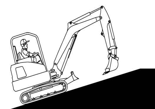
•Do not travel across or up slopes that are over 15 degrees.
•Do not travel down or back up slopes that exceed 25 degrees.
•Look in the direction of travel.
W-2497-0304
When going down a slope, control the speed with the steering levers and the engine speed control lever or dial.
Travelling Down or Backing Up Slopes
Warning
AVOID INJURY OR DEATH
•Avoid steep areas or banks that could break away.
•Keep boom centred and attachments as low as possible when travelling on slopes or in rough conditions. Look in the direction of travel.
•Always fasten seat belt.
W-2498-EN-1009
Travelling Up Slopes
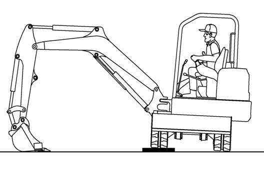
When going down grades that exceed 15 degrees, put the machine in the position shown, and run the engine slowly [Figure130]

Operate as slow as possible and avoid sudden changes in lever direction.
Avoid travelling over objects such as rocks, trees, stumps, etc.
Stop the machine before moving the upper equipment controls. Never allow the blade to strike a solid object. Damage to the blade or hydraulic cylinder can result.
When travelling up slopes or on side slopes that are 15 degrees or less, position the machine as shown and run the engine slow [Figure131] and [Figure132].