6 minute read
AIR CLEANER SERVICE


Standard
Replace the large (outer) filter element only when the red ring shows in the window of the condition indicator (Item 1) [A]
NOTE:Before replacing the filte element, push the button on the condtion indicator (Item 2) [A], start the engine. If the red ring does not show, do not replace the filter element.
Replace the inner filter every third time the outer filter is replaced or when the red ring still shows in the indicator window after the outer fiolter has been replaced.
Optional
It is important to change the air filter element only when the service code (on the instrument panel) shows the symbols as in the figure [B].
Service the air cleaner as follows:
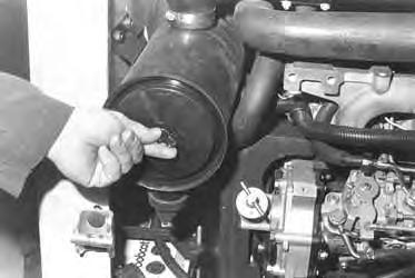
Remove the dust cover wing nut [C]
Remove the dust cover [D].
AIR CLEANER SERVICE (Cont’d)
Servicing The Air Cleaner (Cont’d)
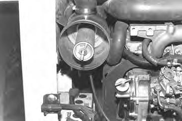
Remove the wing nut at the large air filter element [A].
Remove the large filter element [B].
NOTE:Make sure all sealing surfaces are free of dirt and debris.
Install the new filter element and tighten the wing nut. Install the dust cover and tighten the wing nut.
NOTE:Make sure the evacuator is in the down position.
Check the air intake hose for damage. Check the air cleaner housing for damage. Check to make sure all connections are tight.
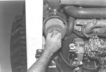
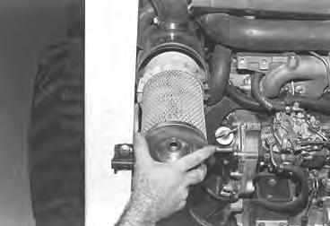
Only replace the inner filter element under the following conditions [C]:
1.Replace the inner filter element every third timethe outer filter is replaced.
2.Replace the inner filter element when the service codes show symbols AF.2, only after the outer filter element has been changed and the engine speed is at full RPM.
Fuel System
Fuel Specifications
Use only clean, high quality fuel. Use Grade No. 2 fuel above 40° F (4° C). Use Grade No. 1 fuel at temperatures below 40° F (4 ° C).
Filling The Fuel Tank
Stop and cool the engine before adding fuel. NO SMOKING! Failure to obey warnings can cause an explosion or fire.
W–2063–0887
Remove the fuel fill cap (Item 1) [A].
Use a clean, approved safety container to add fuel of the correct specifications. Add fuel only in an area that has free movement of air and no open flames or sparks. NO SMOKING! [B].
Install and tighten the fuel fill cap [A].
Fuel Filter
Always clean up spilled fuel or oil. Keep heat, flames, sparks or lighted tobacco away from fuel and oil. Failure to use care around combustibles can cause explosion or fire which can result in injury or death.
W–2103–1285
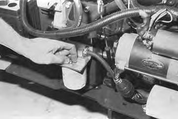
See the SERVICE SCHEDULE Page 29 for the service interval when to remove water from the fuel filter.
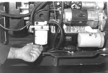
Loosen the drain at the bottom of the filter element to drain the water from the filter [C]
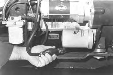
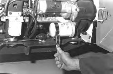
See the SERVICE SCHEDULE Page 29 for the service interval when to replace the fuel filter.
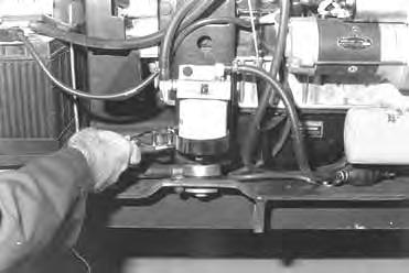
Use a filter wrench to remove the filter element [D].
Clean the area around the filter housing. Put oil on the seal of the new filter element. Install the fuel filter, hand tighten the filter element.
Remove the air from the fuel system. (See Removing Air From The Fuel System Page 38.)
FUEL SYSTEM (Cont’d)
Removing Air From The Fuel System
After replacing the fuel filter element or when the tankhas run out of fuel, the air must be removed from the fuel system to start the engine
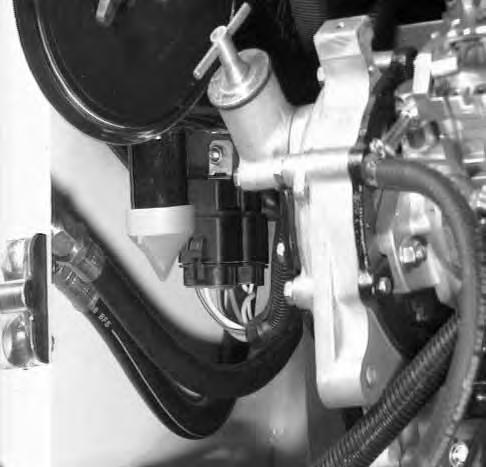
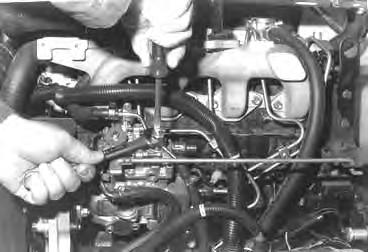
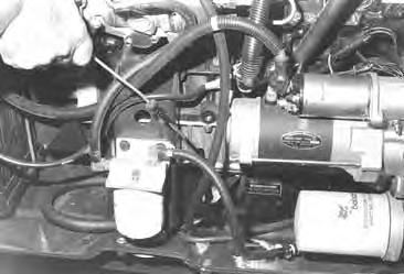
Loosen the air vent plug at the top of the fuel filter [A]
Operate the priming bulb until fuel flows from the filter vent plug [B]. Tighten the fuel filter vent plug.
Loosen the air vent plug at the top of the fuel injection pump [C]
Again operate the priming bulb until fuel flows from the air vent plug with no air bubbles showing [B]
Tighten the air vent plug at the fuel injection pump [C]
Always clean up spilled fuel or oil. Keep heat, flames, sparks or lighted tobacco away from fuel and oil. Failure to use care around combustibles can cause explosion or fire which can result in injury or death.
Engine Lubrication System
Checking Engine Oil
Check the oil level every day.
Before starting the engine for the work shift,open the rear door remove the dipstick [A]
Keep the oil level between the marks on the dipstick. Use a good quality motor oil that meets API Service Classification of CC, CD or CE (See Oil Chart Below).
RECOMMENDED SAE VISCOSITY NUMBER (LUBRICATION OILS FOR ENGINE CRANKCASE)
TEMPERATURE RANGE ANTICIPATED BEFORE NEXT OIL CHANGE DIESEL: USE API CLASSIFICATION CC,CD or SE)
Replacing Oil And Filter
See the SERVICE SCHEDULE Page 29 for the service interval for replacing the engine oil and filter.
Run the engine until it is at operating temperature. Stop the engine.
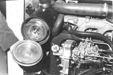
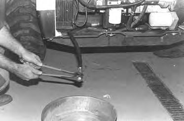
Open the rear door. Remove the drain plug [B]. Drain the oil into a container.
Remove the oil filter [C]
Clean the filter housing surface. Put clean oil on the oil filter gasket. Install the filter and hand tighten only. Install and tighten the drain plug.
ENGINE LUBRICATION SYSTEM (Cont’d)
Replacing Oil And Filter (Cont’d)
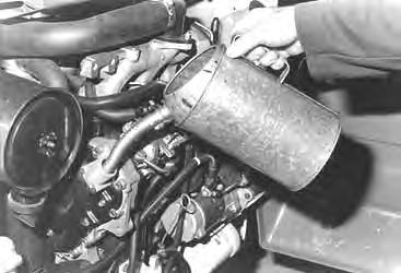
Remove the filler cap [A].
Put 8 qts. (7,6 L) of oil in the engine [B]. (See Checking Engine Oil Page 39.)
Start the engine and let it run for several minutes. Stop the engine. Check for leaks and check the oil level. Add oil as needed if not at the top mark on the dipstick.
Always clean up spilled fuel or oil. Keep heat, flames, sparks or lighted tobacco away from fuel and oil. Failure to use care around combustibles can cause explosion or fire which can result in injury or death.
W–2103–1285
Cooling System
Check the cooling system every day to prevent overheating, loss of performance or engine damage.
• When fluids are under pressure.
• Flying debris or loose material is present.
• Engine is running.
• Tools are being used.
Wear safety glasses to prevent eye injury when any of the following conditions exist: W–2019–1285
Cleaning The Cooling System
Raise the rear grill.
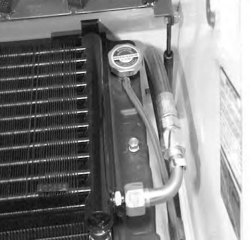
Use air pressure or water pressure to clean the top of the oil cooler [A]
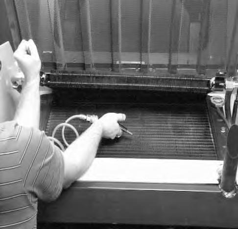

Raise the oil cooler and clean on the top of the radiator [B]
Check cooling system for leaks.
Checking The Coolant Level
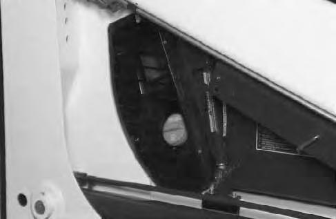
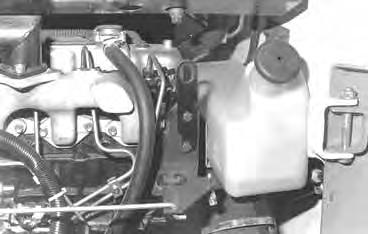
Open the rear door. Check the coolant level in the coolant recovery tank on the right side of the engine [C]
The coolant recovery tank must be 1/3 full (engine cold).
Add premixed coolant, 50% water and 50% ethylene glycol to the recovery tank if the coolant level is low.
COOLING SYSTEM (Cont’d)
Removing Coolant From The Cooling System
Do not remove radiator cap when the engine is hot. You can be seriously burned.
Open the rear door. Open the rear grill.
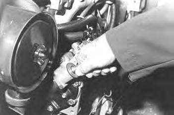
Remove the radiator cap (Item 1) [A].
Connect the drain plug from the side of the engine block [B] drain the coolant into a container.
After the coolant is removed, install and tighten the drain plug.
NOTE:The loader is factory filled with propylene glycol coolant. DO NOT mix propylene glycol with ethylene glycol.
Propylene Glycol
Add premixed coolant, 47% water and 53% propylene glycol to the recovery tank if the coolant level is low.
One gallon and one pint of propylene glycol mixed with one gallon of water is the correct mixture of coolant to provide a –34°F (–37°C) freexe protection.
Use a refractometer to check the condition of propylene glycol in your cooling system.
Mix the coolant in separate container. (See SPECIFICATIONS Page 71 for correct capacity.)
Fill the radiator and engine block with the premixed coolant. Install the radiator cap.
Fill the coolant recovery tank 1/3 full.
Run the engine until it is at operating temperature. Stop the engine. Check the coolant level in the recovery tank when cool. Add coolant to the recovery tank as needed.
Alternator Belt
Adjusting The Alternator Belt
To adjust the belt tension for the alternator, use the following procedure:
Stop the engine.
Raise the operator cab. (See Raising The Operator Cab Page 31.)
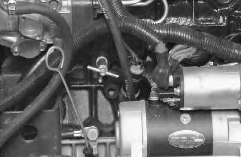
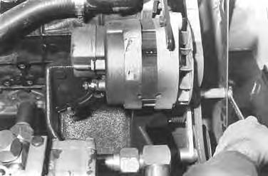
Loosen the alternator mounting bolt (Item 1) [A]
Loosen the adjustment bolt (Item 2) [A].
Move the alternator until the belt has 5/16 inch (8,0 mm) movement at the middle of the belt span with 15 lbs. (66 N) force.
ELECTRICAL SYSTEM Description
The loader has a 12 volt, negative ground alternator charging system. The electrical system is protected by fuses located in the instrument panel or the engine compartment. The fuses will protect the electrical system when there is an electrical overload. The reason for the overload must be found before starting the machine again.
Servicing The Electrical System
The battery cables must be clean and tight. Check the water level in the battery. Remove any acid or corrosion from the battery and cables with a sodium bicarbonate and water solution [A]
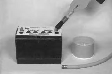
Cover the battery terminals and cable ends with grease.
Batteries contain acid which burns eyes and skin on contact. Wear goggles, protective clothing and rubber gloves to keep acid off body.
In case of acid contact, wash immediately with water. In case of eye contact get prompt medical attention and wash eye with clean, cool water for at least 15 minutes.
If electrolyte is taken internally drink large quantities of water or milk! DO NOT induce vomiting. Get prompt medical attention. W–2065–1296
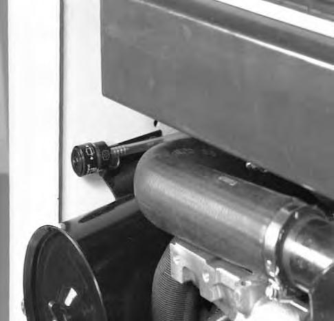
Fuse Location – 853 (Optional) & 853H (Option)
The electrical system for loaders is protectedby two fuses (Item 1) [B] installed in the wiring harness. Fuses protect the electrical system from an overload. The fuses are located in the engine compartment under the air cleaner.
Fuse Location – 853 (Standard)
The electrical system for this model loader is protected by two fuses (Item 1) [C] located in the instrument panel.