25 minute read
INSTRUMENT PANEL (Cont’d)


Standard
The instrument panel has the following instruments [A]:
1. LIGHT SWITCH (OPT.) – Controls the work and travel lights.
2. KEY SWITCH – For starting, stopping and preheating the engine.
3. FUSE (ACCESSORIES) – To protect the electrical system from overload.
4. FUSE (IGNITION) – To protect the electrical system from overload.
5. HOURMETER – Records the total operating hours of the loader.
6. FUEL GAUGE – Shows the amount of fuel in the fuel tank.
7. ENGINE TEMPERATURE GAUGE – Shows the engine coolant temperature.
8. ENGINE WARNING LIGHT – Engine oil pressure is low. Stop the engine if the light comes ON.
9. TRANSMISSION WARNING LIGHT – Low transmission charge pressure, hydraulic filter needs replacement or high fluid temperature. Stop the engine if the light comes ON.
10. VOLTMETER – Shows the condition of the battery and the rate of charge.
11. PREHEAT BUTTON – For preheating the glow plugs before starting the engine.
12. AUXILIARY HYDRAULICS MODE SWITCH (OPT.) – For engaging the auxiliary hydraulics (front & rear).
Instrument Panel
Optional BOSS®
The following items are located on the instrument panel [A] & [B]:
1. IGNITION SWITCH – Controls the starting and stopping of the engine. If engine doesn’t start turn the key to the OFF position for 3 seconds to reset the fuel timer module.
2. LIGHT SWITCH (OPTIONAL) – Controls the work and travel lights.
3. DIAGNOSTIC COUPLER – Connector for diagnostic tool to make service checks of the system operation unit and other components.
4. DISPLAY PANEL – The display has the following symbols and functions (Ref. 5 thru 18).
5. OPTIONAL AUXILIARY HYDRAULICS MODE SWITCH – For Engaging The Auxiliary Hydraulics (Front And Rear).
6. FUEL – Shows the amount of fuel in the tank.
7. BATTERY VOLTAGE – Shows the condition of the battery and charge rate. Also will indicate a WARNING for high and low voltage.
8. ENGINE OIL SYMBOL – Shows engine oil pressure. Flashing symbol indicated low oil pressure.
9. ENGINE COOLANT SYMBOL – Shows engine coolant temperature and/or low coolant level (SHUTDOWN).
10. FUEL FILTER – If fuel pump and bar flashes it is a low fuel WARNING H2O symbol indicates water in the fuel filter (NOT FUNCTIONAL AT THIS TIME).
11. SHUTDOWN SYMBOL – The symbol is associated with any shutdown condition. When this symbol comes ON the shutdown will occur in 30 seconds. During shutdown the buzzer will sound continuously and the symbol will flash until the key is turned OFF.
NOTE:The engine can be restarted for 30–second periods to move the loader after a shutdown condition.
12. WARNING SYMBOL – The symbol will be ON when any warning or shutdown is activated. The warning symbol is also used to indicatea warning if there is no related symbol on the display. During a warning the buzzer will beep three times andsymbol will be on continuously.
13. HOURMETER – Records the total operating hours of the loader. The five character code will display the operating hours to the nearest tenth. When SHUTDOWNS or WARNINGS occur an alpha–numeric code will be displayed in the hourmeter area to inform the operator of the problem (See Page 59 for code listing). During a SHUTDOWN or WARNING the hourmeter symbol is not visible.
14. CHARGE PRESSURE AND FILTER CONDITION
– Flashing symbol indicates low fluid charge pressure and SHUTDOWN. If arrows are ON with gear/drop it is fluid charge pressure.This symbol will also indicate a clogged hydraulic fluid filter.
15. AIR FILTER CONDITION – This symbol will indicate a clogged air filter element.
16. GLOW PLUG – The symbol will flashwhen the glow plugs are energized. The hourmeter will also contain characters GLOXX where XX indicates the remaining time the glow plugs will beON. Glow plug will count down in 5 second increments.
17. ENGINE SPEED – This symbol will indicate an engine overspeed WARNING and SHUTDOWN.
18. PARKING BRAKE – This symbol will indicate when the brake is engaged (NOT FUNCTIONAL AT THIS TIME.
19. HYDRAULIC FLUID TEMPERATURE – This symbol will indicate a high fluid temperature and SHUTDOWN or WARNING.
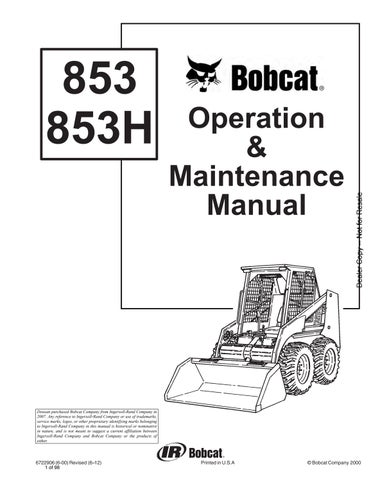
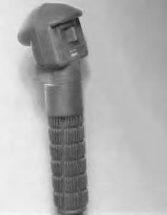
Engine Speed Control
The engine speed control (Item 1) [A] is at the right side of the operator’s seat. Engine speed is controlled by moving the speed control forward to increase the engine RPM and backward to decrease the engine RPM.
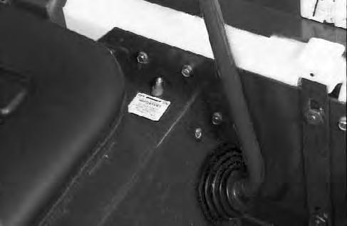
Parking Brake
Lock the parking brake by pushing down on the top (toe) of the pedal [B].
Avoid Injury Or Death
When operating the machine:
• Keep the seat belt fastened snugly.
• The seat bar must be lowered.
• Keep your feet on the pedal controls.
W–2046–0595
The steering lever (Item 1) [A] are on the right and left side in front of the seat.
For safe control of the loader always move the levers slowly and smoothly. Only a small movement is necessary to move the loader.
The steering levers control forward and reverse travel of the loader [B]
Forward Travel – Push both levers forward.
Reverse Travel – Pull both levers backward.
Normal Turning – Move one lever farther forward than the other.
Fast Turning – Push one lever forward and pull the other lever backward.

For slow travel speed, push the steering levers forward only a small amount.
To increase travel speed, push both levers farther forward.
For maximum pushing force, push the levers forward only a small amount with the engine at full RPM.
Reverse
RIGHT TURN 853 Bobcat Loader Operation & Maintenance Manual –6–
Left Turn
Hydraulic Controls
Foot Pedals
Keep both feet on pedals while operating machine. Failure to do so can cause serious injury.
W–2002–1285
Clean dirt and debris from the foot pedals and surrounding area before operating the loader, to ensure proper operation of the foot pedals.
Put your feet on the pedals and KEEP THEM THERE any time you operate the loader.
Two foot pedals (Item 1) [A] control the hydraulic cylinders for the lift and tilt function.
Lift Arm Operation
The left pedal controls the lift arms. Push on the bottom (heel) (Item 2) [A] of the pedal to raise the lift arms.
Push on the top (toe) (Item 3)[A] of the pedal to lower the lift arms.
Push the top (toe) (Item 3) [A] of the lift pedal all the way forward until it locks into detent (float). Use the float position of the lift arms to level loose material while driving backward.
Tilt Operation (Bucket)
The right pedal controls the action of the bucket. Push the top (toe) (Item 4)[A] of the pedal to tiltthe bucket forward.
Push the bottom of the pedal (heel) (Item 5)[A] to tilt the bucket backward.
Bucket Position Valve Operation (Optional)
The function of the bucket positioning valve isto keep the bucket in the same approximate position it is placed in, prior to the upward lift cycle.
Bucket positioning functions automatically during the upward lift cycle only.
HYDRAULIC CONTROLS (Cont’d)
Auxiliary Hydraulics Operation (Optional)
Described below is the operation ofthe optional auxiliary hydraulics used with the standard instrument panel.
Press the mode switch (Item 1) [A] (on the instrument panel) to allow for the front and rear auxiliary hydraulics, the light (Item 2) [A] will come ON.

The switch (Item 1)[B] on the rightsteering lever controls the front auxiliary hydraulics and the switch (Item 2) [B] on the left steering lever control the rear auxiliary hydraulics.

Switch (Item 4) [B] controls the optional horn.
(OPTIONAL) FRONT AUXILIARY CONTROL:
Push switch (Item 1) [B] in the right or left direction (with mode switch engaged & top light ON to change fluidflow direction to the front quick couplers[C]. (Example: Open and close grapple teeth.)

(OPTIONAL) REAR AUXILIARY CONTROL:
Push the switch (Item 2) [B] in the right or left direction (with mode switch engaged & top light ON to change the fluid flow direction to the rear quick couplers [C]. (Example: Raise or lower rear stabilizers.)
DETENT CONTROL:
Push the mode switch (Item 1) [A] the second time to engage the detent function and both lights (Items 2 & 3) [A] will come ON. Push the front button (Item 3) [B] to give the front auxiliary hydraulics a constant flow of fluid. (Example: Operate a backhoe.)
To release the detent position, push the switch (Item 3) [B] again.
RELIEVE PRESSURE AT FRONT QUICK COUPLERS:
Turn the key switch to the OFF position, as the engine stops running, turn the key switch all the way to the left (hold the key in this position until the engine stops) to release the hydraulic pressure at the front quick couplers.
RELIEVE PRESSURE AT REAR QUICK COUPLERS:

With the engine running, press the mode switch (Item 1) [A] to engage the auxiliary hydraulics, the light (Item 2) [A] will come ON.
Push the heel of the tilt pedal so the hydraulic fluid goes over the main relief pressure and at the same time push switch (Item 2) [B] back and forth several times to relieve the pressure at the rear quick couplers. Release the tilt pedals. Stop the engine.

Left Right Steering Lever (Optional)
853 Bobcat Loader Operation & Maintenance Manual –8–
HYDRAULIC CONTROLS (Cont’d)
Auxiliary Hydraulics Operation (With Optional BOSS ®)
Described below is the operation of the optional auxiliary hydraulics used with the standard instrument panel.
NOTE:The right and left steering lever control are blank (no switches) as standard.
Press the mode switch (Item 1) [A] (on the instrument panel) to allow for the front and rear auxiliary hydraulics, the light (Item 2) [A] will come ON.
The switch (Item 1) [B] on the right steering lever controls the front auxiliary hydraulics and the switch (Item 2) [B] on the left steering lever control the rear auxiliary hydraulics.

Switch (Item 4) [B] controls the optional horn.
(OPTIONAL) FRONT AUXILIARY CONTROL:
Push switch (Item 1) [B] in the right or left direction (with mode switch engaged & top light ON to change fluid flow direction to the front quick couplers [C]. (Example: Open and close grapple teeth.)
(OPTIONAL) REAR AUXILIARY CONTROL:
Push the switch (Item 2) [B] in the right or left direction (with mode switch engaged & top light ON to change the fluid flow direction to the rear quick couplers [C] (Example: Raise or lower rear stabilizers.)
DETENT CONTROL:
Push the mode switch (Item 1) [A] the second time to engage the detent function and both lights (Items 2 & 3) [A] will come ON. Push the front button(Item 3) [B] to give the front auxiliary hydraulics a constant flow of fluid. (Example: Operate a backhoe.)
To release the detent position, push the switch (Item 3) [B] again.
RELIEVE PRESSURE AT FRONT QUICK COUPLERS:
Turn the key switch to the OFF position, as the engine stops running, turn the key switch all the way to the left (hold the key in this position until the engine stops) to release the hydraulic pressure at the front quickcouplers.
RELIEVE PRESSURE AT REAR QUICK COUPLERS:
With the engine running, press the mode switch (Item 1) [A] to engage the auxiliary hydraulics, the light (Item 2) [A] will come ON.
Push the heel of the tilt pedal so the hydraulic fluid goes over the main relief pressure and at the same time push switch (Item 2) [B] back and forth several times torelieve the pressure at the rear quick couplers. Release the tilt pedals. Stop the engine.
853 Bobcat Loader Operation & Maintenance Manual –9–
HYDRAULIC CONTROLS (Cont’d)
Auxiliary Hydraulics Operation – 853H (Optional)
Press the mode switch (Item 1) [A] (on the instrument panel) once to engage the auxiliary hydraulics, for momentary operation. The light (Item 2) [A] will come ON. Press the mode switch a secondtime for continuous operation. Both lights (Items 2 & 3) [A] will come ON. Pressing the mode switch a third time will disengage the auxiliary hydraulics and both lights will be OFF.
The buttons (switches) (Item 1 through Item 5)[B] on the right and left steering levers control the front and rear auxiliary hydraulics.
Button (Item 6) [B] controls the optional water kit. Button (Item 7) [B] controls the optional horn. Button (Item 8)[B] controls the optional left/right turn signals .
FRONT AUXILIARY CONTROL (Momentary) (Normal Flow):
Push buttons in the right or left direction (Item 1)[B] (with mode switch engaged) for momentary or continuous operation to change fluid flow direction to the front quick couplers (Item 1) [C]. (Example: Open and close grapple teeth.)

FRONT AUXILIARY CONTROL (Continuous) (Detent) (Normal Flow):
Push the front button (Item 2) [B] one (with mode switch engaged for continuous operation) for continuous flow to the front auxiliary quick couplers (Item 1) [C]. (Example: backhoe). To disengage continuous (detent) flow, push button (Item 2) [B] a second time.
If the high horsepower switch is in the ON position, (See Auxiliary High Horsepower Hydraulics Operation, Page 10). High Horsepower Hydraulics will flow through the front auxiliary quick coupler (Item 1) [C]. Damage to unapproved attachments can result.


I–2106–0196
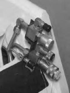
SECONDARY AUXILIARY (Optional) (Momentary Only):
There is also a set of couplers (Item 2) [C] on the right front of the loader. These couplers are used when there is an additional connection needed for attachment operation (Example: Side shift on the planer).

Push button (Item 3) [B] in the right or left direction (with mode switch engaged) for momentary operation, to change the fluid flow direction to the secondary auxiliary couplers (Item 2) [C]. (Example: side shift on the Planer.)
Push the top or bottom of either button (Item 4 or Item 5) [B] (with mode switch engaged for momentary or continuous operation) to change fluid flow direction to the attachments.
NOTE:When the loader is equipped with the second and rear auxiliary hydraulics, disconnect the rear auxiliary couplers so both front and rear do not function at the same time.
HYDRAULIC CONTROLS (Cont’d)
Auxiliary Hydraulics Operation – 853H (Optional) (Cont’d)
REAR AUXILIARY CONTROL (OPTIONAL);
Engage the mode switch for momentary operation (one light). Push button (Item 3) [B] Page 9 right or left to change the fluid flow direction to the rear quick couplers (Item 1) [A]. (Example: Raise and lower the rear stabilizers.)
NOTE:When the loader is equipped with rear and second auxiliaries, disconnect the second auxiliary couplers so both auxiliaries do not function at the same time.
Relieve Pressure At Optional Rear Couplers

With the engine OFF, use a rag to cover the quick couplers and top tap the poppet with a wooden dowel. this will release trapped pressure in the hydraulic circuit.
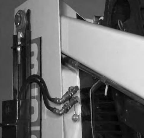
RELIEVE PRESSURE AT FRONT COUPLERS
With the engine running, turn ignition switch quickly to the left (counterclockwise) past the OFF position and hold until engine comes to a complete stop. This relieves pressure that may be trapped in the front auxiliary circuit which would hinder the engagement of attachment couplers.
AUXILIARY HIGH HORSEPOWER HYDRAULICS OPERATION:
The ON/OFF toggle switch (Item 1)[B] located on the left side of the operator’s seat controls the High Horsepower function.
The High Horsepower function provides additional GPM to the system to operate a High Horsepower attachment (Example: Planer). There is a total of 24 GPM available to operate the attachment. System pressure is also increased from 2300 PSI to 3300 PSI while the High Horsepower function is in use.
NOTE:Use only the large quick couplers for the High Horsepower function.
With the toggle switch in the OFF position, connect the attachment quick couplers to the large quick couplers (Item 1) [C] on the left front of the loader. The High Horsepower attachment may have a case drain which needs to be connected to the screw on male coupler (Item 2) [C] on the left front of the loader.
When all the couplers are connected turn the toggle switch to the ON position. For continuous high pressure/high flow in forward direction push the Detent button (Item 2) [B] Page 9 on the front side of the right steering lever (the mode switch must bein the continuous flow mode). (See Page 10.) To stop continuous flow push the Detent button a second time.
Momentary operation of the front auxiliary is also possible with the toggle switch in the ON position (the mode switch must be either in the Momentary or in the Continuous mode). Momentary forward flow (high flow and high pressure) results from pushing the button (Item 1) [B] Page 9 to the right (Example: closing a LaBounty Shear). Momentary reverse flow (high pressure and normal flow) results from pushing the button (Item 1)[B] Page 9 to the left (Example: opening a LaBounty Shear).
Daily Inspection
The loader must be in good operating condition [A] Check the following items:
• Engine Oil
• Hydraulic/Hydrostatic Fluid
• Engine Cooling System
• Operator Cab, Seat Belt, Seat Bar & Pedal Interlocks
• Lift Arm & Cylinder Pivot Pins
• Tires
• Any Loose or Broken Parts
• Safety Tread & Safety Signs
• Check the instrument panel display readout for faulty codes (See SERVICE CODES Page 59.)
Follow the maintenance requirements on the Service Schedule Decal, located inside the rear door [B]
NOTE:Fluids such as engine oil, hydraulic fluid, coolants, etc. must be disposed of in an environmentally safe manner. Some regulations require that certain spills and leaks on the ground must be cleaned in a specific manner. See local, state and federal regulations for correct disposal.
Instructions are necessary before operating or servicing machine. Read Operation & Maintenance Manuals, Handbook and signs (decals) on machine. Follow warnings and instructions in the manuals when making repairs, adjustments or servicing. Check for correct function after adjustments, repairs or service. Failure to follow instructions can cause injury or death [A]. W–2003–1289
Seat Bar Restraint System
The seat bar restraint system has a pivoting seat bar (Item 1) [A] with arm rests and has spring loaded interlocks for the lift and tilt control pedals. The operator controls the use of the seat bar. The seat bar in the down position helps to keep the operator in the seat. The interlocks require the operator to lower the seat bar in order to operate the foot pedal controls. When the seat bar is up, the lift and tilt control pedals are locked when returned to the neutral position.
AVOID INJURY OR DEATH
When operating the machine:
• Keep the seat belt fastened snugly.
• The seat bar must be lowered.
• Keep your feet on the pedal controls.
W–2046–0595
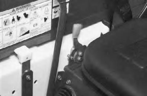
The spring loaded interlocks (Item 1) [B] control the locking and unlocking functions of the control pedals.
The interlocks (Item 1) [B] require the operator to lower the seat bar (Item 2) [B] which allows the operator to move the foot pedals to control the lift and tilt functions.

When the seat bar is lowered, it pushes the interlock (Item 1) [B] down on both sides, releasing the pedal linkages (Item 3) [B] from the interlocks.
The pedals will pivot in both directions when the interlock is down.
AVOID INJURY OR DEATH
Before you leave the operator’s seat:
• Lower the lift arms, put the attachment flat on the ground.
• Stop the engine.
• Engage the parking brake.
• Raise seat bar, move pedals until both locked.
W–2045–1086
AVOID INJURY OR DEATH
The seat bar system must lock the lift and tilt control pedals in neutral when the seat bar is up. Service the system if pedals do not lock correctly.
W–2105–1285
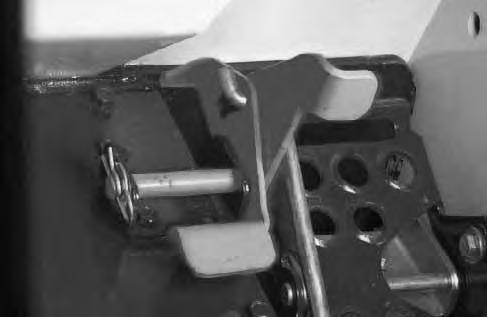
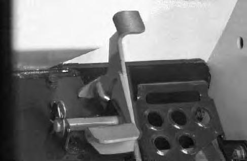
When the seat bar is raised, spring forces raise the interlocks [C]
The foot pedals will not pivot when the interlock is up.
See Seat Bar Inspection Page 33 and Seat Bar Maintenance Page 33.
Getting Ready For Operation
Read the Operation & Maintenance Manual and the Operator’s Handbook before operating the loader [A]
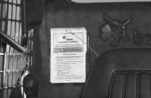
Operator must have instructions before running the machine. Untrained operators can cause injury or death.
W–2001–0596
Use the bucket or attachment steps, grab handles and safety treads (on top of the loader lift arms and frame) to get on and off the loader [B]
Safety treads are installed on the Bobcatloader to provide a slip resistant surface for getting on and off the loader. Keep safety treads clean and replace when damaged. Replacement treads are available from your dealer.
Pull the seat lever (Item 1)[C] and adjust the seat position for comfortable operation of the loader controls.


Fasten the seat belt snugly and adjust it so that the buckle is centered between the hips [D]
Avoid Injury Or Death
When operating the machine:
• Keep the seat belt fastened snugly.
• The seat bar must be lowered.
• Keep your feet on the pedal controls.
W–2046–0595
GETTING READY FOR OPERATION (Cont’d)
Lower the seat ba r [A]
All controls must be in the neutral position before you start the engine. (See Normal Starting Condition Pages 16 & 18.)
I–2105–0196
Starting The Engine
When an engine is running in an enclosed area, fresh air must be added to avoid concentration of exhaust fumes. If the engine is stationary, vent the exhaust outside. Exhaust fumes contain odorless, invisible gases which can kill without warning.
W–2050–1285
Avoid Injury Or Death
• Engines can have hot parts and hot exhaust gas. Keep flammable material away.

• Do not use machines in atmosphere containing explosive gas.
W–2051–1086

STARTING THE ENGINE (Cont’d)
Normal Starting Condition – (Standard)
Adjust the seat position for comfortable operation of the foot pedals and steering levers.
Fasten the seat belt snugly and adjust it so the buckle is centered between the hips.
Lower the seat bar [A]
Put the foot pedals and steering levers in neutral (center) position (Item 1) [B]

Set the engine speed control to the half speed position (Item 2) [B]
Turn the key to the ON position. The engine and transmission warning lights will be ON when thekey is on and the engine is stopped (Item 3) [B].
Turn the key to start position (Item 4) and release it when the engine starts [B]
Do not engage the starter for longer than 15 seconds at a time. Longer use can damage the starter by overheating. Cool the starter for one minute between uses.
I–2034–0284
When the engine starts, release the key and it will return to the run position (Item 5) [B].
STOP THE ENGINE IF THE WARNING LIGHTS DO NOT GO OFF.
Without turning the key to the START position, turn the key to the RUN position (Item 5)[B] for starting theloader in cold weather. (See Cold Temperature Starting Condition Page 17 & 19.)
Do not use ether with glow plug (preheat) systems. Explosion can result which can cause injury or death.
W–2071–1285
Cold Temperature Starting Condition – (Standard)
See Normal Starting Condition, Page 18. Turn the key switch to the RUN position.
Push the PREHEAT switch (Item 1) [A] on the left side of the instrument panel to preheat the glow plugs.
Refer to the decal on the left side of the operator cab for operation of the preheat system [B]
Follow the steps under Normal Starting Condition and repeat the Preheating procedure until the engine starts.
If the temperature is below 32°F (0°C), use the following procedure to make starting the engine easier:
Replace the engine oil with the correct type and viscosity for the anticipated starting temperature. (See Oil Specifications, Page 39.)
Make sure the battery is at full charge.
Install a block or tank heater on the engine.
Warming The Hydraulic/Hydrostatic System
When the temperature is below –20°F (–30°C), hydrostatic oil must be warmed before starting. The hydrostatic system will not get enough oil at low temperatures and will be damaged. Park the machine in an area where the temperature will be above 0°F (–18°C) if possible.
I–2007–1285
Let the engine run for a minimum of 5 minutes to warm the engine and hydrostatic trasmission fluid before operting the loader. If the warning light comes ON when operating the loader (cold), more warm up time is needed.
STARTING THE ENGINE (Cont’d)
Normal Starting Condition – (Optional)
Adjust the seat position for comfortable operation of the foot pedals and steering levers.
Fasten the seat belt snugly and adjust it so the buckle is centered between the hips.
Lower the seat bar [A]
Put the foot pedals and steering levers in neutral (Center) position (Item 1) [B]
Set the engine speed control to 1/2speed position (Item 2) [B].
Turn the key to the ON position, one beep will sound and the display symbols will be ON [C]. Turn the key to START. (See Cold Temperature Starting Condition Pages 17 & 19.) Release the key when the engine starts.
Do not engage the starter for longer than 15 seconds at a time. Longer use can damage the starter by overheating. Cool the starter for one minute between uses.
I–2034–0284
When the key is turned ON and the alpha numeric display will show various readout codes for three secondintervals each. The readout codes are from the previous work shift when a WARNING may have occurred. (See SERVICE CODES Page 59.)
The readout codes may be viewed again by turning the key switch OFF and then ON again without starting the engine.
Once the engine is started, the microprocessor will clear out all the codes from memory. The codes will not reappear in subsequent key ON conditions unless the problem recurs.
When the readout codes are completed, the numerical display will return to the operating hours.
STARTING THE ENGINE (Cont’d)
Do not use ether with glow plug (preheat) systems. Explosion can result which can cause injury or death.
W–2071–1285
NOTE:If display is showing readout codes (see above description), the timing of the glow plug activation may be obscured on the display. However the glow plugs will actually be energized.
The alpha numeric display will indicate the characters GLOXX where XX will show remaining time the glow plugs will be energized. The following chart shows the time glow plugs will be energized dependent on engine coolant temperature.
See Normal Starting Condition Pages 17. Turn the key switch to the ON position (readout codes will show first) and the glow plug signal will be ON [A] GLOW
0
0°–50°F. (–18°–10°C.)15 Seconds
50°–70°F. (10°–21°C.) 5 Seconds
70°F (21°C) & Above NO TIME
Turn the key to the START position and release when the engine starts. If the engine does not start, turn the key switch to the OFF position and ONagain to cycle the glow plugs again. When the engine is running, slowly move the engine speed control forward to increase the RPM.
If the starting temperature is below 32° F (0° C), use the following procedure to make starting easier:
Replace the engine oil with the correct type and viscosity for the anticipated starting temperature. (See Checking Engine Oil Page 39.)
Make sure the battery is at full charge. Install an engine block heater or tank heater.
Stopping The Engine
Pull the throttle fully backward to decrease the engine RPM. Turn the key switch to the OFF position.
When the temperature is below –20°F (–30°C), hydrostatic oil must be warmed before starting. The hydrostatic system will not get enough oil at low temperatures and will be damaged. Park the machine in an area where the temperature will be above 0°F (–18°C) if possible. I–2007–1285
Never use attachments or buckets which are not approved by Bobcat Company. Buckets and attachments for safe loads of specified densities are approved for each model. Unapproved attachments can cause injury or death.
W–2052–1285
The dealer can identify, for each model loader, the attachments and buckets approved by BobcatCompany. The buckets and attachments are approved for Rated Operating Capacity and for secure fastening to the Bob–Tach.
The Rated Operating Capacity for this loader is shown on a label in the operator cab. (See SPECIFICATIONS , Page 71.)
It is determined by using a standard dirt bucket, and material of normal density, such as dirt or dry gravel. If longer buckets are used and load center moves forward and reduces the Rated Operating Capacity. If very dense material is loaded, the volume must be reduced.
Exceeding the Rated Operating Capacity can cause the following problems:
1.Steering the loader may be difficult.
2.Tires may wear faster.
3.There will be a loss of stability.
4.The life of the Bobcat loader will be reduced. Use the correct size bucket for the type and density of material being handled. For safe handling of materials and avoiding machine damage, the attachment (or bucket) should handle a full load without going over the Rated Operating Capacity for the loader. Partial loads make steering more difficult.
Maximum loads to be carried when using a pallet fork are shown in figure [B]
Avoid Injury Or Death
B–06587
Do not exceed rated operating capacity. Excessive load can cause tipping or loss of control.
W–2053–0887
WEIGHT OF LOADS LBS. (KG) CENTER
ATTACHMENTS AND BUCKETS (Cont’d)
Installation And Removal
The loader is equipped with the Bob–Tach system. The Bob–Tach is used for fast changing of buckets and attachments. See the Attachment Operation & Maintenance Manual to install other attachments.
Bob–Tach levers have spring tension. Hold lever tightly and release slowly. Failure to obey warning can cause injury.
W–2054–1285
Pull the Bob–Tach levers all the way up.
Tilt the Bob–Tach forward. Drive the loader forward until the top edge of the Bob–Tach is completely under the flange of the bucket [A].
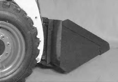
DO NOT hit the Bob–Tach levers on the bucket.
Tilt the Bob–Tach backward until the bucket is off the ground [B]. Stop the engine.
Avoid Injury Or Death
Before you leave the operator’s seat:
• Lower the lift arms, put the attachment flat on the ground.
• Stop the engine.
• Engage the parking brake.
• Raise seat bar, move pedals until both locked.
W–2045–1086
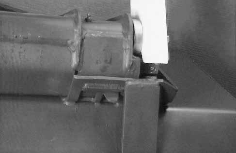
Push down on the Bob–Tach levers until they are in the locked position [C]. Inset [C] is locked position.
Bob–Tach wedges must extend through the holes in attachment. Lever(s) must be fully down and locked. Failure to secure wedges can allow attachment to come off and cause injury or death.


W–2102–0497
The wedges (Item 1) [D] must extend through the holes in the bucket or attachment.
Removal: Reverse the above procedure to remove the bucket or attachment from the Bob–Tach.
Operating Procedures
When operating on a public road or highway, always follow local regulations. For example: Slow Moving Vehicle Sign or Directional Signals may be required.
Always warm up the engine and hydrostatic system before operating the loader.
WITH BUCKET FULL
Machines warmed up with moderate engine speed and light load have longer life.
I–2015–0284
Operate the loader with the engine at full speed for maximum horsepower. Move the steering levers only a small amount to operate the loader slowly.
New operators must operate the loader in an open area without bystanders. Operate the controls until the loader can be handled at an efficient and safe rate for all conditions of the work area.
With a full bucket, go up to down the slope with theheavy end toward the top of the slope [A] & [B]
With empty bucket, go down or up the slope with the heavy end toward the top of the slope [C] & [D]
Going Up Slope
WITH BUCKET FULL
Going Down Slope
WITH BUCKET EMPTY
AVOID INJURY OR DEATH
• Keep the lift arms as low as possible.
• Do not travel or turn with the lift arms up.
• Turn on level ground.
• Go up and down slopes, not across them.
• Keep the heavy end of the machine uphill.
• Do not overload the machine.
Failure to obey warnings can cause the machine to tip or roll over and cause injury or death.
W–2018–1187
Raise the bucket only high enough to avoid obstructions on rough ground.
WITH BUCKET EMPTY
Going Down Slope D B–13297
Going Up Slope
OPERATING PROCEDURES (Cont’d)
Filling The Bucket
Push down on the top of the lift pedal until the lift arms are all the way down. Push the top of the tilt pedal to put the cutting edge of the bucket on the ground [A].
Drive slowly forward into the material. Push the bottom of the tilt pedal to raise the front of the bucket [B]
Load, unload and turn on flat level ground. Do not exceed rated operating capacity shown on sign (decal) in cab. Failure to obey warnings can cause the machine to tip or roll over and cause injury or death.
W–2056–1187
Drive backward away from the material.
Emptying The Bucket
Push down on the bottom of the lift pedal to raise the bucket over the truck box or bin [C]
Drive forward slowly until the bucket is over the top of the truck box or bin. Push the top of the tilt pedals until the bucket is empty [C]. If all the material is near the side of the truck or bin, push it to the other side with the bucket.
Never dump over an obstruction, such as a post, that can enter the operator cab. The machine could tip forward and cause injury or death.
W–2057–0694
OPERATING PROCEDURES (Cont’d) Digging Into The Ground
Put the lift arms all the way down. Push the top of the tilt pedal until the cutting edge of the bucket is on theground. Drive forward slowly and continue to tilt the bucket down until it enters the ground [A]
Push the bottom of the tilt pedal a small amount to increase traction and keep an even digging depth. Continue to drive forward until the bucket is full. Whenthe ground is hard, raise and lower the cutting edge of the bucket with the tilt pedal while driving forward slowly.
Push the bottom of the tilt pedal to the tilt the bucket backward as far as it will go when the bucket is full [B]
Leveling The Ground (Using Lift Arms In Float Position)
Push the top (toe) of the lift pedal all the way forwarduntil the pedal is in the locked position (detent) to put the lift arms in a float position [C]
Push the tilt pedal to change the position of the cutting edge on the bucket. With the bucket tilted farther forward, there is more force on the cutting edge and more loose material can be moved.
Never drive forward when the hydraulic control for lift arms is in float position.
I–2005–1285
Drive backward to level loose material. Push the bottom of the lift pedal to unlock from the detent position.
OPERATING PROCEDURES (Cont’d)
Backfilling
Lower the lift arms and put the cutting edge of the bucket on the ground. Drive forward to the edge of the hole to push the material into the hole [A].
Tilt the bucket forward as soon as it is past the edge of the hole [A]. If necessary, raise the lift arms to empty the bucket.
Parking The Bobcat Loader
Stop the Bobcat loader on level ground.
Lower the lift arms fully and put the edge of the bucket on the ground.
Pull the engine speed control all the way backward. Turn the key switch to the OFF position.
Avoid Injury Or Death
Before you leave the operator’s seat:
• Lower the lift arms, put the attachment flat on the ground.
• Stop the engine.
• Engage the parking brake.
• Raise seat bar, move pedals until both locked.
W–2045–1086
Engage the parking brake.
Lift the seat bar and make sure the foot pedals are in the locked position.
Unbuckle the seat belt. Remove the key from the switch to prevent operation of the loader by unauthorized personnel.
Transporting The Bobcat Loader
Adequately designed ramps of sufficient strength are needed to support the weight of the machine when loading onto a transport vehicle. Wood ramps can break and cause personal injury.
W–2058–0494
A loader with an empty bucket or no attachment must be loaded backward onto the transport vehicle [B]
The rear of the trailer must be blocked or supported [B] when loading or unloading the loader to prevent the front end of the trailer from raising up.
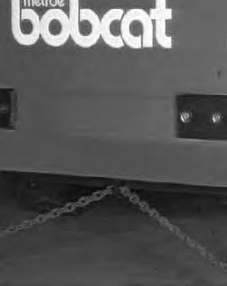
Use the following procedure to fasten the Bobcat loader to the transport vehicle to prevent the loader from moving during sudden stops or when going up or down slopes.
Lower the bucket or attachment to the floor [C].
Stop the engine. Engage the parking brake. Install chains at the front and rear of the loader and to to the transport vehicle.

Lifting The Loader
Four Point Lift
AVOID INJURY OR DEATH
When operating the machine:
• Keep the seat belt fastened snugly.
• The seat bar must be lowered.
• Keep your feet on the pedal controls.
W–2046–0595
The loader can be lifted with the four point lift which is available as a kit from your Bobcat loader dealer.
Install the lift eyes [A] in the kit as shown.
Single Point Lift
AVOID INJURY OR DEATH
• Before lifting, check fasteners on single point lift and operator cab.
• Assemble front cab fasteners as shown in this manual.
• Never allow riders in the cab or bystanders within 15 feet (5 meters) while lifting the machine.
W–2007–0497
The loader can also be lifted with the singlepoint lift which is available as a kit from your Bobcat loader dealer.
Install the kit and lift as shown [B]
The single point lift, supplied by Bobcat Company is designed to lift and support the Bobcat loader without affecting roll over and falling object protection features of the operator cab.