11 minute read
ELECTRICAL SYSTEM (Cont’d)


Battery Removal And Installation
Batteries contain acid which burns eyes and skin on contact. Wear goggles, protective clothing and rubber gloves to keep acid off body.
In case of acid contact, wash immediately with water. In case of eye contact get prompt medical attention and wash eye with clean, cool water for at least 15 minutes.
If electrolyte is taken internally drink large quantities of water or milk! DO NOT induce vomiting. Get prompt medical attention.
W–2065–1296
Open the rear door. Disconnect the negative (–) battery cable first [A]
Disconnect the positive (+) battery cable.
Remove the battery holddown clamp (Item 1) [B]

Remove the battery from the loader.
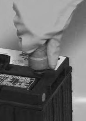
Always clean the terminals and cable ends when installing a new battery [C].
When installing the battery in the loader, do not touch any metal parts with the battery terminal posts.
Connect and tighten the battery cables. Connect the negative (–) cable last to prevent sparks.
HYDRAULIC/HYDROSTATIC SYSTEM Checking And Adding Fluid
Use only recommended fluid in the hydraulic system (See SPECIFICATIONS for the correct fluid, Page 53.)
To check the fluid level in the reservoir, use the following procedure:
Put the Bobcat loader on a level surface. Lower the lift arms and tilt the Bob–Tach fully back. Stop the engine.
Remove the dipstick (Item 1) [A].
The fluid level must be between the marks on the dipstick. Remove the fill cap (Item 2) [A] and add fluid as needed.
Hydraulic Filter Replacement
See The SERVICE SCHEDULE Page 25 for the correct service interval.
Raise the operator cab (See Page 27.)
Remove the filter element (Item 1) [B]
Clean the surface of the filter housing where theelement contacts the head.
Put clean oil on the rubber gasket of the filter element. Install the filter and hand tighten.
Hydrostatic Filter Replacement
See the SERVICE SCHEDULE Page 25 for the correct service interval.
NOTE:The filter must be replaced when the warning light comes on during loader operation.
Remove the filter element (Item 1) [C]
Clean the surface of the filter housing where theelement contacts the head.
Put clean oil on the rubber gasket of the filter element. Install the filter and hand tighten.
Record the operating hours of the loader on the decal (Item 1) [D] inside the rear door.
HYDRAULIC/HYDROSTATIC SYSTEM (Cont’d)
Hydraulic Fluid Replacement
See the SERVICE SCHEDULE Page 25 for the correct service interval.
The fluid must also be replaced if it becomes contaminated or after major repairs.
Remove the fill cap.
Remove the screen from the fill pipe [A]
Check the screen for damage. Clean the screen in solvent.
Remove the fluid from the reservoir with a hand operated suction pump or a fluid lift pump [B]
Install the screen.
Replace the hydraulic and hydrostatic filter elements. (See Page 40.)
Add fluid to the reservoir until the fluid level is between the marks on the dipstick. DO NOT fill above the top mark on the dipstick.
Start the engine and operate the loader hydraulic/hydrostatic functions. Stop the engine. Check the fluid level and add as needed.
Always clean up spilled fuel or oil. Keep heat, flames, sparks or lighted tobacco away from fuel and oil. Failure to use care around combustibles can cause explosion or fire which can result in injury or death.
W–2103–1285
Spark Arrestor Muffler
See the SERVICE SCHEDULE Page 25 for service interval for cleaning the spark arrestor muffler.
Do not operate the loader with a defective exhaust system.
This loader is factory equipped with a U.S.D.A. Forestry Service approved spark arrestor muffler. It is necessary to do maintenance on this spark arrestor muffler to keep it in working condition. The spark arrestor muffler must be serviced by dumping the spark chamber every 100 hours of operation.
If this machine is operated on flammable forest, brush or grass covered land, it must be equipped with a spark arrestor attached to the exhaust system and maintained in working order. Failure to do so will be in violation of California State Law, Section 4442 PRC.
Make reference to local laws and regulations for spark arrestor requirements.
Stop the engine. Open the rear door.
Remove the plug (Item 1) [A] at the bottom of the muffler.
Failure to obey can cause serious injury.
When the engine is running during service, the steering levers must be in neutral and the parking brake engaged. Failure to do so can cause injury or death.
Start the engine and run for about 10 seconds while a second person wearing safety glasses holds a piece of wood over the outlet of the muffler.
Stop the engine. Install and tighten the plug. Close the rear door.
When an engine is running in an enclosed area, fresh air must be added to avoid concentration of exhaust fumes. If the engine is stationary, vent the exhaust outside. Exhaust fumes contain odorless, invisible gases which can kill without warning.
Never use machine in atmosphere with explosive dust or gases or where exhaust can contact flammable material. Failure to obey warnings can cause injury or death.
Tire Maintenance
Wheel Nuts
See the SERVICE SCHEDULE Page 25 for the service interval to check the wheel nuts. The correct torque is 105–115 ft.–lbs. (142–156 Nm).
Tire Rotation
Check the tires regularly for wear, damage and pressure (See SPECIFICATIONS , Page 53 for the correct tire pressure.)
Rear tires usually wear faster than front tires. To keep tire wear even, move the front tires to the rear and rear tires to the front [A].
It is important to keep the same size tires on each side of the loader to avoid excessive wear. If different sizes are used, each tire will be turning at a different speed and cause excessive wear. When tires wear, install two new tires on the same side of the loader. The tread bars of all the tires must face the same direction.
Recommended tire pressure must be maintained to avoid excessive tire wear and loss of stability and handling capability. Check for the correct pressure before operating the loader.
Tire Inflation
Tires are to be repaired only by an authorized person using the proper procedures and safety equipment. Tires and rims must always be checked for correct size before mounting. Check rim and tire bead for damage.
The rim flange must be cleaned and free of rust. The tire bead and rim flange must be lubricated with a rubber lubricant before mounting the tire, avoid excess pressure which can rupture the tire and cause serious injury or death. During inflation of the tire, check the tire pressure frequently to avoid over–inflation.
FINAL DRIVE TRANSMISSION (CHAINCASE)
Checking And Adding Oil
The chaincase contains the final drive sprockets and chains and uses the same type of oil as the hydraulic/hydrostatic system (See SPECIFICATIONS Section, Page 53.)
To check the chaincase oil level, use the following procedure: Drive the loader onto a level surface. Stop the engine. Remove the plug (Item 1)[A] at the front of the chaincase housing.
If oil can be reached with the tip of the your finger through the hole the oil level is correct.
If the level is low, add oil through the check plug hole until the oil flows from the hole. Install and tighten the plug.
Lubrication Of The Bobcat Loader
Lubricate the Bobcat loader as specified in theSERVICE SCHEDULE Page 25 for the best performance of the loader [A].
Always use a good quality lithium based multi–purpose grease when you lubricate the loader. Apply the lubricant until the extra grease shows.
Record the operating hours each time you lubricate the Bobcat loader.
GREASE
See the SERVICE SCHEDULE Page 25 for the service interval when to grease the U–joints.
Raise the operator cab (See Page 27.)
Use a special U–joint grease (P/N 6599719) to assure correct lubrication of the U–joints fittings (Item 1) [B].
See the SERVICE SCHEDULE Page 25 for the service interval when to grease the steering lever pivot bearings and oil the shaft.
Grease the pivot bearings for the steering levers [C]
Fitting Located Between Fender and Control Box Under Cab
LUBRICATION OF THE BOBCAT LOADER (Cont’d)
Add oil as needed to the steering control shaft [A]. Lubricate the seat rails for easy movement of the seat.
BOB–TACH
Check for free movement of wedges and Bob–Tach levers.
The wedges must extend far enough to engage theholes in the attachment [B]
Bob–Tach wedges must extend through the holes in attachment. Lever(s) must be fully down and locked. Failure to secure wedges can allow attachment to come off and cause injury or death.
W–2102–0497
Replace wedges that are bent or broken.
PIVOT PINS
All pivot pins in the lift arms, Bob–Tach and cylinders have a large pin held in position with a retainer bolt and nut (Item 1) [C]
Check that the retainer bolt and lock nut are tightened to 18–20 ft.–lbs. (24–27 Nm) torque.
Parking Brake Adjustment
Loosen the lock nut (Item 1) [D] and turn the nut on the linkage rod (Item 2) [D] to adjust the brake pedal.
There must be 1/4 inch (6,35 mm) of movement under the bottom edge (heel) of the brake pedal.
Tighten the jam nut when the adjustment is correct.
Troubleshooting
The following information identifies loader problems which can occur most often. Service procedures for correcting loader problems can be found in this manual on the pages indicated. Some procedures are marked D/S (Dealer Service) and must be performed only by qualified Bobcat service personnel. Instructions are necessary before operating or servicing machine. Read Operation & Maintenance Manuals, Handbook and signs (decals) on machine. Follow warnings and instructions in the manuals when making repairs, adjustments or servicing. Check for correct function after adjustments, repairs or service. Failure to follow instructions can cause injury or death W–2003–1289
Engine won’t turn over with starter.
Battery has low charge.
Cables loose or dirty.
Damaged starter, solenoid or wiring.
Charge battery and find cause of discharge.
Clean and tighten the battery cables.
Check the starting circuit. Repair as needed.
Engine turns with starter, but is difficult to start.
Wrong starting procedure.
Air in the fuel.
Auxiliary control lever orlift pedal is in detent
No fuel in tank.
Vent in fuel filler cap is plugged.
Dirt or water in fuel system.
Fuel filter is dirty.
Hole in fuel line.
Weak battery.
Wrong oil in engine.
Cylinder compression is low.
Engine has overheated.
Poor fuel quality.
Restricted exhaust.
Use correct starting procedure.
Check & repair as needed.
Take out of detent.
Add fuel.
Clean the vent.
Repair as needed.
Install a new filter.
Repair as needed.
Charge or replace battery.
See Oil Specifications.
Recondition the engine.
Check cooling system.
Use fresh, good quality fuel.
Clean exhaust system.
Engine has little power or runs rough.
D/S = Dealer Service Only
Injectors are not working correctly.
Dirt, water or air in fuel system.
Clean and repair as needed.
Clean and repair as needed.
TROUBLESHOOTING THE ENGINE (Cont’d)
Engine has little power or runs rough (Cont’d).
Engine is hot.
Restricted exhaust.
Dirty air cleaner
Cylinder compression is low.
See Engine Overheats
Clean exhaust system
Install new element.
Recondition the engine.
Engine overheats.
Restriction in cooling air flow.
Blower shroud damaged or missing.
Engine is overheated.
PROBLEM
No drive on both sides.
No drive on one side.
Machine pulls to one side.
Check for debris on radiator grill.
Check shroud and repair or replace as needed.
Troubleshooting The Drive System
Hydraulic fluid is low.
Damaged hydraulic pump.
Hydrostatic system is damaged. Control linkage is disconnected.
Hydrostatic system is damaged.
Wrong tire pressure.
Steering linkage out of adjustment.
Damaged hydrostatic system.
Check fluid level. Add as needed.
Check condition of pump and replace as needed.
Check hydrostatic system.
Repair linkage.
Check hydrostatic system and make repair as needed.
Check all tires for correctpressure.
Check steering linkage and adjust as needed.
Machine moves when levers are in neutral.
System is overheating.
Steering linkage out of adjustment. (26001 & Above) Servos out of adjustment.
Hydraulic fluid level is low.
Cooling system is dirty. Air restricted.
Low charge pressure (transmission light on).
Auxiliary control in detent.
Loader is overloaded.
Check system. Repair as needed. Adjust steering linkage.
Adjust Steering
Check fluid level and add as needed.
Clean cooling system. Check for debris on radiator grill.
Check by–pass valve.
Take out of detent.
Use correct size attachment.
Parking brake will not hold.
D/S = Dealer Service Only
Hydrostatic transmission damage. Out of adjustment.
Check system and make repair.
Adjust parking brake.
Troubleshooting The Hydraulic System
No hydraulic action.
No hydraulic oil.
Pedals are disconnected.
Relief valve is damaged.
Hydraulic pump is damaged.
Hydraulic fluid is too thick.
Check fluid level and add as needed.
Check linkage. Repair as needed.
Replace the relief valve.
Check pump. Replace as needed.
Let machine warm up.
Hydraulic action is rough.
Hydraulic fluid level is low.
Pedal is hitting floor or debris under pedal.
Check fluid level and add as needed.
Check adjustment. Remove debris.
Hydraulic action is slow.
Cylinders leak internally.
Hydraulic pump is damaged. Control valve is damaged.
Check condition of cylinders and repair as needed.
Check pump. Replace as needed.
Check valve and repair as needed.
Hydraulic cylinders leak fluid.
D/S = Dealer Service Only
Hydraulic fluid is too thick. Damage to cylinder rods or seals.
Let machine warm up.
Repair cylinders.
843b Loader Specifications
Specifications
• Dimensions are given for loader equipped with standard tires and dirt bucket. Dimensions may vary with other types. All dimensions are shown in inches. Respective metric dimensions are given in millimeters enclosed by parentheses.
• Where applicable, specifications conform to SAE standards and are subject to change without notice.
This loader was designed without counterweights or ballasts. Changes of structure or weight distribution of the loader can cause changes in control and steering response and can cause failure of the loader parts.
Performance
Weights Operating Weight6480 lbs. (2942 kg) Rated Operating Capacity 1700 lbs. (772 kg) . . . . . . . . . . . . Tipping Load 3420 lbs. (1553 kg)
Travel Speed Infinitely variable 0–6.3 MPH (10 km/hr.)
Controls
Vehicle Direction & speed controlled by two hand levers. Loader Function Lift & Tilt Function: Controlled by separate foot pedals. . . . . . . . . . . . . . . . . . . . .
Auxiliary function (opt.) controlled by the right steering lever
Engine Hand lever throttle & key–type starter switch; Main Drive Hydrostatic
Parking Brake Mechanical disc, foot operated pedal . . . . . . . . . . . . . . . . . . . . . .
ENGINE Make Isuzu Model 4JBIPK01
Fuel Diesel Horsepower 54 HP (40,3 kW) @ 2700 RPM
Maximum Governed RPM 2600 RPM . . . . . . . . . . . .
Torque 120 ft.–lbs. (163 Nm) Maximum @ 1600 RPM
Number of Cylinders Four . . . . . . . . . . . . . . . . .
Bore/Stroke 3.66/4.02 (93/102) . . . . . . . . . . . . . . . . . . . . . . . .
Displacement 169 cu.in (2770 cm 3)
Cooling SystemLiquid . . . . . . . . . . . . . . . . . . . . .
LubricationPressure System W/Filter
Crankcase Ventilation Open . . . . . . . . . . . . . . . .
Air Cleaner Dry replaceable cartridge, with safety element
Low Idle 2725–2775 RPM
High Idle 1200 RPM
HYDRAULIC SYSTEM
Hydraulic PumpEngine driven gear type–Rated @ 1050 PSI (7240 kPa)
Pump (Front) 10.8 GPM (40,9 L/min.) Hydraulic Pump (Rear) 16.2 GPM (61,3 L/min.)
Hydraulic Fluid Filters Hydraulic Replaceable #4 Micro Element
3 spool, open center, series type W/float detent on lift, detent on lift, detent on auxiliary
Bucket Position Valve (Opt.) Provides bucket positioning when lift arms are raised
Fluid Lines SAE standard tubes, hoses & fittings
Fluid Type
Bobcat Fluid (P/N 6563328) (5 gal package). If fluid is not available use 10W–30 or 10W–40 Class SE Motor Oil for temperatures above 0° F (–18 ° C), & 5W–30 Motor Oil for temperatures below 0 F (–18 C)
Additional Publications
The following publications are also available for your Bobcat Loader. You can order them from your Bobcat dealer.
OPERATOR’S HANDBOOK
6569119
–gives basic operation instruction and safety warnings.
Skid Steer Loader Operator Training Course
6722720
–Introduces operator to step–by–step basics of Skid–Steer loader operation. Also available in Spanish P/N 6724036.
Maintenance
OPERATION & MANUAL
6720547
–complete instruction on the correct operation and the routine maintenance of the BOBCAT loader.
SAFETY VIDEO 6724793
–provides basic safety instructions.
SAFETY MANUAL 6556500
6566091
–complete maintenance and overhaul instructions for your BOBCAT loader.
–provides basic safety procedures and warnings for your BOBCAT loader. Also available in Spanish P/N 6724451.
–Up–to–date PARTS information is also available. See your BOBCAT dealer.