68 minute read
4–7.3 Installation Of The Axle


Reverse the above steps to install axles. Replace the gasket between the axle and the transmission case if damaged. When installing the axle housing, tighten the upright bolts (Item 3) to 240–280 ft.–lbs. (326–380 Nm) torque (Fig. 4–21). Tighten fastening bolts (Item 8) to the frame to 125–140 ft.–lbs. (170–190 Nm) torque.
NOTE:If repairs are being done on loaders (S/N 15640 & Below) used in heavy work conditions or when solid tires are used also weld the axle housing to the loader main frame (Fig. 4–20a). The welds shown in Figure 4–20a are all that are needed. Any more than this will cause axle housing distortion and removal will not be possible.
4–8 AXLE BEARING AND SEAL REPLACEMENT
1.Remove the axle assembly (axle with housing) from the loader.
2.Remove the inner bearing and axle from the housing.
3.Remove the outer bearing from the axle (Fig. 4–22).
4.Remove the seals and races from the axle housing. Check the wear ring (Fig. 4–27, Item 5) for damage and replace as needed.
NOTE:The early model 825s use a wear ring with an inside diameter of 2.7553–2.7559 inch (69,984–69,999 mm). The later model 825s use a wear ring with an inside diameter of 3.117–3.121 inch (79,17–79,27 mm).
Put heat on the wear ring until it can be removed from the axle. To install a new ring, put LOCTITE on it, heat it and put it on a cold axle.
5.Install new races, outer bearing and seal in housing (Fig. 4–23, 4–24 & 4–25).
6.Install axle in housing. Use a press to prevent damage to the bearing and seal (Fig. 4–26).
7.Use a press to install the inner bearing.
8.Assemble the sprocket on the axle.
9.Tighten the axle nut (Fig. 4–19) until there is no free play.
10.Tighten the nut one slot further to align it with the bolt hole and install the lock bolt and nut.
4–9 INSTALLATION OF AXLE SPROCKET
Install the axle sprockets after the axle is installed in the loader.
To install the axle sprockets:
1.Install the axle sprocket (Fig. 4–27, Item 1).
2.Install the axle nut and tighten the nut until there is no end play to the axle (Fig. 4–27, Item 2).
3.Hit the end of the axle and check for end play.
4.Tighten the axle nut to the nearest hole on the axle nut that will align with the hole in the axle and remove end play from the axle.
5.Install the lock bolt and nut (Fig. 4–27, Item 3 & 4). Tighten the nut to 55–70 in.–lbs. (6,2 – 7,9 Nm).
4–10 PARK BRAKE REMOVAL
1.Lift the lift arms and install cylinder stops (Fig. 4–2).
2.Tilt the ROPS enclosure.
3.Clean area thoroughly.
4.Remove transmission cover.
5.Before removal of the left brake, remove the steering linkage. Brake linkage rod and hydraulic oil pickup tube.
Before removal of the right brake, removesteering linkage and steering arm from the pump. Remove the brake linkage rod.
6.Remove shoulder screws from the case and lift out brake assembly. Use caution not to drop the actuator lever from the bottom of the brake assembly (Fig. 4–28).
Reverse the above steps to install the brake.
5 Main Frame
5–1.1 Description (Fig. 5–1)
The loader main frame is separate from the upright frame assembly. The main frame is the housing for the drive system and is part of the support for the engine.
5–2 REMOVAL OF ROPS
1.Remove rear fastening bolts (one on each side).
2.Lift the lift arms about 12.0 inches (30 cm) off the stops and hold with blocks.
3.Tilt the ROPS forward, disconnect the electrical wiring connectors (2) and remove the ground strap.
4.Attach a chain to the ROPS, connect to an overhead hoist and take up all loose play.
5.Remove the two front pivot bolts.
6.Remove the bolt which fastens the tilt assembly to the cab (Fig. 5–2for electric tilt and Fig. 5–6 for mechanical tilt).
7.Lift ROPS vertically until it clears the steering handles. TO INSTALL THE ROPS, REVERSE THE ABOVE PROCEDURE.
5–3 PIVOT PIN AND BUSHING REPLACEMENT (Fig. 5–3)
1.Remove the pivot pin thru bolts.
2.Connect the hoist and lift the rear of the lift arms until it is clear of the uprights.
3.Remove the bushings with a driver tool.
4.Use a bushing driver and install new bushings.
NOTE:Make sure that when the new bushings are installed that thegrease hole in the bushing and the hole in the lift arm is in correct alignment.
5.Lower the lift arms into place and install new pivot pins. Fasten with thru bolts.
5–4 BOB–TACH REMOVAL (Fig. 5–3)
1.Tilt the Bob–Tach forward until it is flat on the ground.
2.Stop the engine and engage the tilt pedal to release the hydraulicpressure on the system.
3.Remove the tilt cylinder pivot pins (rod end).
4.Remove the Bob–Tach lower pivot pin.
5.Remove the Bob–Tach.
6.Reverse the above steps to install.
5–5 LIFT ARMS REMOVAL (Fig. 5–3)
1.Remove the Bob–Tach.
2.Remove the lift cylinder pivot pins at rod end.
3.Remove the auxiliary and rear tilt hose lines.
4.Attach overhead hoist and take up all play.
5.Remove the rear thru bolts and pivot pins.
6.Remove the lift arm assembly.
5–6 FUEL TANK REMOVAL
5–6.1 Removing Fuel Tank On Loader S/N 16999 & Below (Fig. 5–1)
1.Remove the engine.
2.Remove or loosen the hoses and electrical wires.
3.Loosen the upright frame to axle housing bolts and move the frame about 1.0 inch toward the rear.
4.Remove the fuel tank fastening bolts.
5.Move the fuel tank toward the rear and remove from under the loader.
5–6.2 Removing Fuel Tank On Loader S/N 17001 & Above (Fig. 5–4)
1.Remove the filler hose.
2.Disconnect the sender wire.
3.Remove the fuel outlet hose.
4.Install a floor jack under the belly pan.
5.Remove the bolts on the belly pan.
6.Lower the floor jack with the belly pan to remove the gas tank.
5–7 ELECTRIC MOTOR FOR ROPS (Cab Tilt – S/N 19126 & Below)
The cab tilt mechanism (Fig. 5–2) is an electric screw jack. Do not service this unit. If there is a defect, make a replacement of the complete unit.
Bushings
5–7.1 Removal Of Tilt Mechanism
1.Tilt the ROPS forward and hold with overhead hoist.
2.Remove the electrical wires to the motor.
3.Remove the fastening bolts.
4.Remove the motor.
5.Reverse to install.
NOTE:If water enters the motor through the electrical wire opening it will cause failure of the tilt motor. To prevent this problem, thoroughly clean this area with rubbing alcohol. Use a R.T.V. (Room Temperature Vulcanizing) type compound to close the opening (Fig. 5–5, Item 1).
5–8 MECHANICAL TILT FOR THE ROPS (S/N 19127 & Above)
The ROPS tilt mechanism (Fig. 5–6) is a mechanical operated screw jack. The mechanical jack is operated by turning the adjustment bolt on the jack (Fig. 5–7).
If the jack is repaired or replaced, make sure the ROPS is supported by a chain hoist.
The ROPS fastening bolts must be tightened to 120 – 150 ft.–lbs. (163 – 203Nm) torque.
6 Electrical System
6–1 ELECTRICAL CIRCUITRY
There are two basic circuits in the electrical system:
1.Charging circuit.
2.Starting circuit.
The ignition switch must be turned on to activate these circuits.
The charging circuit includes the alternator, (with integral regulator), warning indicator light (CLT) and battery.
The starting circuit includes the starter, solenoid and other parts needed to turn the engine.
NOTE:When using an extra battery (jump start) to start the engine the ground wire (Fig. 6–1, Item 1) can burn through the insulation. Replace the ground wire (Fig. 6–1, Item 1) with a 4 gauge wire. Do not put the ground wire through the harness clip.
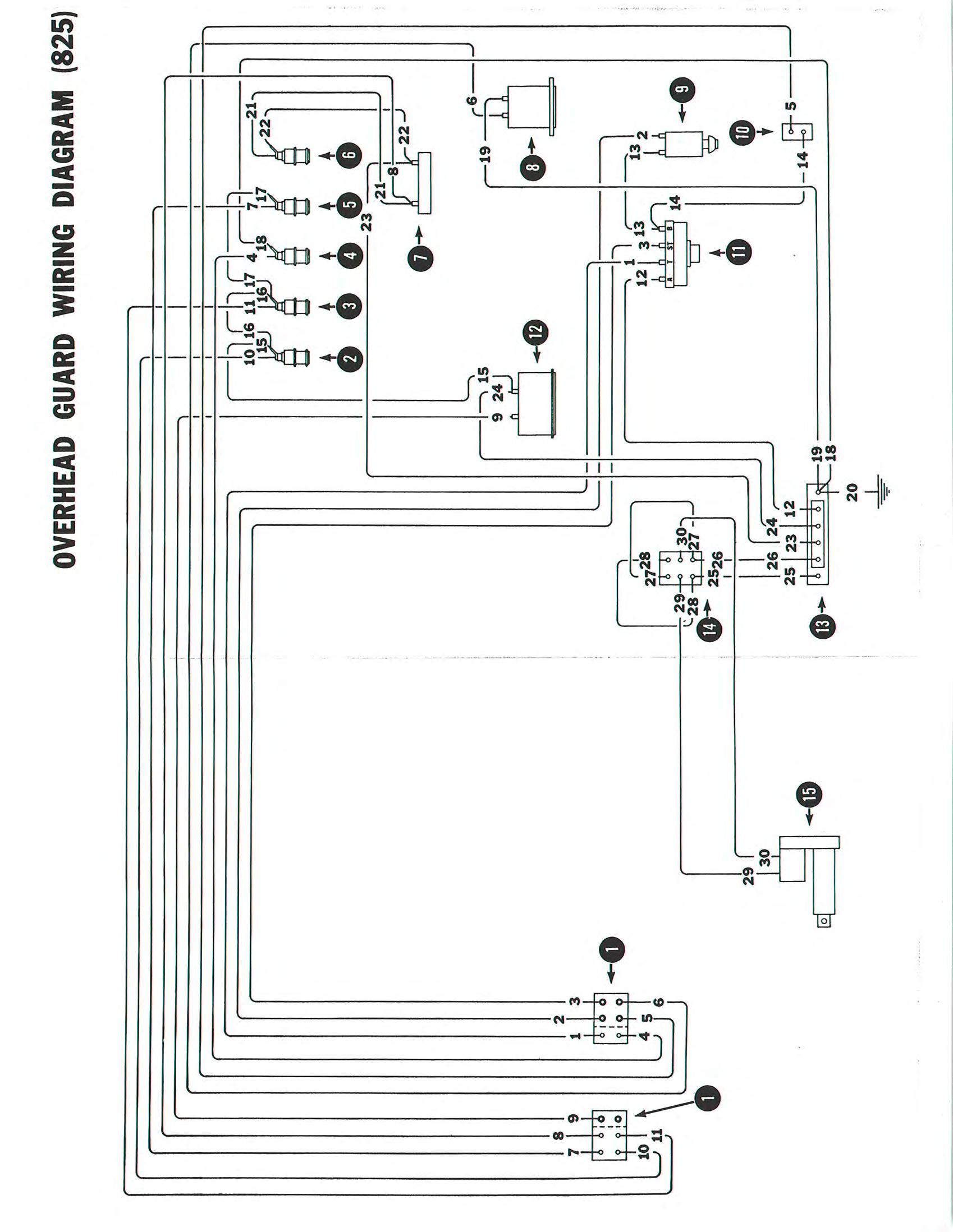
See Figure 6–1 for wiring diagram.
The two most common problems with the electrical system are:
1.Battery loses charge.
2.Starter will not turn engine. Refer to problem analysis charts to find problem with starting orcharging circuits.
Important
When working on the electrical circuitry, first remove the ground (negative) cable from the battery.
I–2155–1297
6–2 PROBLEM ANALYSIS
See the charts for diagnosis of electrical problems:
Chart 1: Battery loses charge.
Chart 2: Starter won’t turn engine over.
The charts give the correct sequence for finding problems and making repairs.
Chart A Battery Loses Charge
6–3 FAN BELT
Check the drive belt for correct tension. A loose belt can cause charging problems. Correct tension is 0.375 inch (10 mm) play at the midway point (Fig. 6–2).
A new belt must be installed when:
1.It is worn narrow.
2.It has cracks or is separating.
3.It has oil on it.
4.There is no more adjustment.
To check wiring:
1.Turn the ignition switch on. Connect a voltmeter from chassis to: (Fig. 6–3) No. 1 alternator connection No. 2 alternator connection Bat connection
2.If any of these connections show zero voltage, the wiring has defect. Find defect and make repair. Then check voltage again.
6–4 TO CHECK ALTERNATOR OUTPUT
1.Put the machine on safe blocks.
2.Disconnect negative battery cable. Connect an ammeter in line with the Bat terminal of the generator. Connect the battery cable.
3.Lower the electric charge in battery. (Turn engine with starter, connect lights, etc.)
4.Start engine and run at full throttle. The minimum indication on the ammeter must be 22 amperes.
5.If the indication is correct, the alternator is good. If the indication is high or low, check the regulator.
6–5 TO CHECK THE REGULATOR
1.Leave the ammeter connected as in Paragraph 6–4.
2.Lower the electric charge in battery. (Turn engine with starter, connect lights, etc.)
3.With the engine running at full throttle, connect the alternator field to chassis with a small screwdriver or wire (Fig. 6–4).
4.Check the ammeter. The indication must be 8 – 28 amperes. If indication is correct, the regulator probably has a defect. If indication is not correct, the problem is in the diode trio, the rectifier, the stator or the rotor.
6–6 ALTERNATOR SERVICE
6–6.1
Removal (ROPS Must Be Tilted)
1.Disconnect negative battery cable.
2.Disconnect wires from alternator.
3.Remove the two bolts that hold alternator in placeand lift alternator from the Bobcat.
4.Installation is the reverse of removal.
6–6.2 Disassembly
1.Put a mark across each housing half to help in correct assembly.
2.Remove the pulley from the shaft.
3.Remove the four bolts which hold the housing together.
4.Use a screwdriver to separate each half of housing (Fig. 6–5). Slide the rotor out of the housing.
5.Remove the nuts which hold the three stator wires to the frame. Remove the stator.
6.Disconnect the diode trio.
6–6.3
To Check Rotor (Fig. 6–6)
1.Connect an ohmmeter from one slip ring to the shaft. There must be maximum resistance.
2.Connect an ohmmeter to both slip rings. There must be 21.8 to 24.0 ohms of resistance on the alternator. If not, there is a defect in the rotor.
6–6.4
To Check Stator (Fig.
6–7)
1.Connect a test light from the middle wire connection to one of the outside wire connections. If the light doesn’t come on, there is a defect in the stator.
2.Connect the test light from the middle connection to the other outside connection. If the light doesn’t come on, there is a defect in the stator.
3.Connect the test light from one of the connections to the frame of the stator. If the light comes on, there is a defect in the stator.
B–02113
A–02211
Fig. 6–4 To Check The Regulator
C–01959
Fig. 6–5 Separating Alternator Housing
(Check for Ohmmeter Shorts and Opens)
Check For Grounds
A–01857
Fig. 6–6 Checking Rotor Coil Wires
Check For Opens
Ohmmeter
(Check for Grounds)
B–02108
Fig. 6–6 Checking Stator Coil Wires
a 6–6.5 To Check Diode Trio (Fig. 6–8)
1.Connect a D.C. test light from one of the three connections to the single connection. Then, reverse the connections. The light must come on when connected one way, but not when connected the other way.
Do not use high voltage to check diode trio or rectifier.
W–2306–0298
2.Do Step 1 for the other two diodes.
3.Connect the test light from the middle connection to each outside connection. If the light comes on, there is a defect in the diode trio.
6–6.6 To Check Rectifier (Fig. 6–9)
1.Remove the rectifier from the generator.
2.Tighten the three nuts on the connections.
3.Connect the test light from one connection, to the insulated heat sink. Then, reverse the connections. The light should come on when connected one way, but not when connected the other way.
4.Connect the test light from the grounded heat sink to the same connection. Then, reverse the connections. The light must come on when connected one way, but not when connected the other way.
5.Repeat Steps 3 and 4 on both the other connections. If any of the tests are bad, complete rectifier replacement is necessary.
6–6.7 Assembly
Assembly is basically the reverse of disassembly.
If the regulator is removed, make sure the insulation washers and spacers are in good condition on the two regulator screws (Fig. 6–10).
To install the rotor, put a piece of straight wire through the case tohold the brushes in place (Fig. 6–11).
6–7.1 To Check The Starter
1.Lift the Bobcat on safe blocks. Keep the ignition switch off. Be sure the battery has full charge and the connections are clean and tight.
2.Connect a jumper wire from the S connection on solenoid to the Batt connection on solenoid (Fig. 6–12). Theengine will turn rapidly. If the starter turns, but not the engine, the defect is in starter drive. If the starter doesn’t turn, do this:
3.Connect the jumper from the Batt connection on solenoid to the M terminal on starter (Fig. 6–13). If the starter will turn rapidly, the defect is in the solenoid. If starter does not turn, the defect is in the starter.
6–7.2 To Remove Starter
1.Disconnect negative battery cable.
2.Disconnect the wires from starter connections.
3.Remove the bracket which holds the rear of the starter. Remove the three nuts which hold the starter in place, and lift it out.
6–7.3 Disassembly And Inspection
1.Remove the three screws which hold the solenoid in place. Twist the solenoid 1/4 turn and slide it off.
2.Remove the thru bolts and the shift lever bolt. The starter will now come apart.
3.Check the armature by connecting a test light from the outside of the armature to the commutator (Fig. 6–14). If the light comes on, the defect is in the armature.
4.Check the armature on an armature tester (Fig. 6–15).
5.Check the condition of the commutator, and make repairs as needed.
6.Connect a test light from the outside connection to each of the inside connections (Fig. 6–16). If the light doesn’t come on, the field coils have a defect.
6–7.4 Assembly
Assembly is the reverse of disassembly.
7–1 INTRODUCTION
7–1.1 Engine Parts
Whenever engine parts are ordered, be sure that all information is given. Always quote the engine serial number, engine part number and description.
7–1.2 Engine Number Location
The engine number is stamped on the fuel pump mounting flange as shown in Figure 1–2.
7–2 STARTING A NEW OR RECONDITIONED ENGINE
1.Remove the plug on the thermostat housing so that all the air will be removed from the system when the radiator is filled.
2.Fill the cooling system with a 50 – 50 mixture of antifreeze and water.
3.Start the engine and check to make sure the oil pressure is satisfactory.
NOTE:The oil passages and the rocker arm shaft will need a little time to fill with oil. Once the oil flow to the rocker arms is satisfactory, the rocker arm cover and the air cleaner can be installed.
4.Run the engine at idle (1200 – 1500 RPM) for 10 – 15minutes to let it warm up.
5.After the engine has been warmed up thoroughly it must be stopped and head bolts tightened to the correct torque (See Specifications Section). The valve clearances must be adjusted after the head bolts are tightened.
6.Check for oil and coolant leaks. Check to make sure the coolant and oil levels are correct.
7–3 ENGINE OVERHAUL
For overhaul of cylinder head, it is not necessary to remove the engine from the loader. Remove only those items such as engine cover, fuel lines, hoses, etc., to make clearance to cylinder head possible.
The engine must be removed when it is necessary to overhaul the block assembly. The engine must be at operating temperature and turning at about 175 RPM. The compression must be between 300 and 500 PSI (2069–3448 kPa) with no more than 50 PSI (345 kPa) difference between the cylinders.
7–3.1 Engine Removal
The engine is most easily removed with the engine coolant radiator and transmission oil cooler attached. Remove the engine as follows:
1.Tilt the operator guard forward.
2.Remove the rear grill.
3.Disconnect the battery cables, electrical wiring, fuel lines and throttle linkage.
4.Let out engine oil and disconnect drain hose from the frame connection.
5.Remove the engine cover and muffler.
6.Remove the hydraulic hoses from the oil cooler. Plug the openings.
7.Remove the three engine fastening bolts from the engine supports at the sides and rear of engine.
8.Fasten chain hoist to engine as shown in Fig. 7–1.
9.Lift the engine up and to the rear slowly to release the drive coupling.
7–3.2 Cylinder Head Maintenance
The number of hours run has no effect on when to overhaul the cylinder head on the 4.108 diesel engine, since carbon beyond a small quantity does not form and gather in the combustion chambers and on the pistons as in gasoline engines.
Easy starting and performance should be the determining factors and the cylinder head removed only when it becomes absolutely necessary.
Before starting to overhaul the cylinder head, make sure that all gaskets and any other parts expected to be required are available.
Remove any external foreign matter from the area of the cylinder head cover, injectors and fuel pump. Remove the cylinder head as follows:
1.Completely empty the cooling system by opening the radiator and cylinder block plug and valve.
2.Disconnect the battery terminals.
3.Remove the fastening nuts and remove the muffler from the exhaust manifold.
4.Disconnect the water outlet connection on the front of the cylinder head.
5.Remove the air cleaner.
6.Disconnect the fuel pipe and electrical connection to the starting aid located in the intake manifold.
7.Remove the cylinder head cover together with the breather pipe.
8.Remove the oil feed pipe to the rocker shaft at the cylinder head end.
9.Remove the eight rocker shaft fastening nuts evenly and remove the rocker shaft complete with the oil feed pipe (Fig. 7–2).
10.Remove the eight push rods and place somewhere safe (possibly in the cylinder head cover) to prevent them from being bent.
11.Unscrew the small bolts on the tops of the injectors and remove the leak–off pipe by turning the fitting on top of the fuel filter.
12.Remove the low pressure fuel pipes between the fuel filter and the fuel pump, remove the fuel filter after disconnecting the feed pipe from the lift pump, plug all pipes and openings to prevent entry of foreign particles.
13.Remove the four high pressure fuel pipes from the fuel pump tothe injectors. Plug fuel pump outlet ports.
14.Remove the injector fastening nuts and carefully remove the injectors. Plug the exposed openings on the injectors.
15.Remove the alternator adjusting arm.
16.Remove the cylinder head fastening nuts and lift off the cylinder head completely with intake and exhaust manifolds (Fig. 7–3).
NOTE:During this final operation do not pry with a screwdriver or any other sharp instrument between the cylinder head and block faces. Once the head has been removed it must be placed on a flat surface, such as wood, to prevent any damage to the machined face.
7–3.3 To Remove The Valves
All valves are numbered so that they may be fitted to their original locations during assembly (Fig. 7–4). The cylinder head is marked with corresponding numbers next to the valve seat.
1.Put the cylinder on the bench with the machined face down.
2.Use a valve spring compressor to remove the two collets by compressing the valve springs as shown in figure 7–5. Repeat for each valve to be removed.
3.Remove the spring caps, springs, seals and spring seat. The valves are now free to be removed from their guides when the cylinder head is turned over.
NOTE: O sealing rings are fitted to the inlet valve stems. The inlet valve spring caps have a deeper center portion to fit this seal. During re–assembly, be sure that the correct spring caps are fitted to the inlet valves and the seals are fitted in the sequence detailed on page 7–7.
7–3.4 Combustion Chamber Inserts
When it is necessary to remove combustion chamber inserts from their seats in the cylinder head, they can be pushed out of their locations by a short curved bar through the injector bore. When installing inserts they must be held by expansion washers in the seats to prevent them from turning. The expansion washers are fitted as shown in Figures 7–6 and 7–7.
7–3.4a Reconditioning Cylinder Heads
When reconditioning cylinder heads, it is not always necessaryto replace cracked pre–combustion chamber inserts. As a general rule, inserts having a single straight crack less than 0.250 inch (16 mm) in length going out and away fromeach end of the throat (Fig. 7–7a) are acceptable. If an insert has a crack that turns toward the center of the insert (Fig. 7–7b, Item A) or one starting from the straight edge of the throat (Fig. 7–7b, Item B) it must be replaced.
Also when replacing a cylinder head (supplied without inserts), the inserts may be used from the old head if the inserts are acceptable to the list above.
NOTE:Cracks are easier to see by checking the inside face of the insert.
7–3.5
Cleaning
Plug all openings, oil ways, etc., where the entry of foreign matter could cause damage to the working parts. Remove any carbon carefully from the tops of pistons (a ring of grease between the piston and cylinder wall can help catchloose carbon particles).
Clean the cylinder head face, being careful not to scratch the machined surface. If the water jacket within the cylinder head shows signs of excessive scale, then a special cleaning solution must be used. The cylinder head should be tested for water leakage after this cleaning.
Clean all the studs on top of the cylinder head and those in the top face of the cylinder block. Examine for thread damage or stretching and replace with new ones where necessary.
Any loose studs must be tightened and any cylinder head nuts found with damaged threads replaced.
NOTE:Studs and nuts are phosphate coated. Be sure that only genuine parts are used as replacements.
7–3.6 Inspection
After the cylinder head has been disassembled and cleaned, the following components should be inspected as follows:
1.Valve springs
Valve springs become weak because of the combined effects of heat and the normal working of the springs.
It is best to install new valve springs whenever the engine undergoes an overhaul. Where a top overhaul only is being done, the springs should be inspected, paying special attention to squareness of ends and pressures at specific lengths. The details can be found on page 8–4.
2.Valve
The valve guides should be inspected for wearand if necessary replaced by new ones.
The worn guides should be removed either by press or the valve guide removal tool shown in Figure 7–8, being careful not to damage the bores during their removal.
Before installing new guides, remove any burrsfrom the cylinder head parent bores, then coat the bores with clean oil and either press in the new guides or pull them in by means of the tool shown in Figure 7–9 until the guide protrusion above the head top face is 0.800–0.815 inch.
NOTE:Be careful during this operation since guides are brittle.
3.Valves and Valve Seats
The valves should be checked in their guides for wear and replacement made if worn. Be sure that the wear is on the valve stem and not in the guide bore before making a replacement.
7–3.7 Reconditioning Of Valves And Valve Seats
The valve and valve seat faces using specialized equipment or with grinding compound, according to their condition. A valve seat (hand operated) cutting tool is shown in Figure 7–10. Valves should always be fitted to their original seats and any new valve fitted should be marked to identify its position if removed later. (See Fig. 7–4 for illustration of valve numbering.)
Before installing the valves, be sure to check the valve head depth in relation to the cylinder head face, within the limits given on page 8–3. This depth can be checked, as shown in figure 7–11, by placing a straight edge across the face of the cylinder head, then use a feeler gauge to measure the distance between the straight edge and the head of the valve.
Where this depth is more than the maximum limit and when the fitting of a new valve does not reduce this depth below the maximum limit, then install a new valve seat insert.
When refacing valves or valve seats see that only the minimum amount of metal necessary to obtain a satisfactory seat is removed, and that as narrow a valve seat as possible is maintained.
7–3.8 Valve Seat Inserts
Valve seat inserts are not installed in productionengines. Inserts can be installed in these engines where it is considered necessary.
When installing inserts be sure that only genuine replacement parts are used.
7–3.9 To Install Inserts, Proceed As Follows:
1.Install new valve guides as described on page 7–4.
2.Using a new valve guide bore as a pilot, machine cut the insert area in the cylinder head face to the dimensions shown in Figure 7–12.
3.Remove all loose material and thoroughly clean the cut out area (removing any burrs which may be present.
4.Using the valve guide bore as a pilot once again press the insert in with the insert driver, this tool is shown fully dimensioned in Figure 7–13. Steady pressure should be given with either a hand or a hydraulic press. The purpose of the insert driver is to get squareness when the insert is being pressed in.
NOTE:The insert must not be driven by hammer and lubrication must not be used.
5.Visually inspect to be sure that the insert has been pressed fully in (flush with the bottom of the recess).
6.Cut the valve seat at an included angle of 90 ° (which will give the normal 45° seat) until the valve head depth reaches the minimum limit which is given on page 8–3. Lightly lap the valve to its new seat.
A – 1.530” to 1.531”
B – 0.3125” to 0.3175”
C – 0.015” Chamfer at 45° (Max.)
Fig. 7–12 Valve Insert Detail
INSERT DRIVER (Fig. 7–13)
A – 1.296” to 1.297”
B – 0.3125” to 0.3175”
C – 0.015” Chamfer at 45° (Max.)
A–02350
D.
E. – 0.0625 inch at 45 °
F. – 0.0625 inch at 45 °
– 0.0625 inch at 45 °
G. – 0.0312 inch RadiusG. – 0.03125 inch Radius
H. – 1.238 to 1.239 inchH. – 1.018 to 0.019 inch
J. – 0.222 to 0.225 inch
K. – 1.523 to 1.533 inch
J. – 0.222 to 0.225 inch
K. 1.287 to 1.297 inch
7–3.10 To Disassemble The Rocker Shaft Assembly
1.Remove the snap rings from each end of the rocker shaft.
2.Withdraw the rocker levers, springs and support brackets from the rocker shaft.
3.Unscrew the oil feed pipe from the connector and remove the connector. (When refitting this feed pipe, it should be noted that the end of the pipe locates the connector position on the shaft.)
After disassembly, thoroughly wash all parts in clean solvent. Inspect the rocker bushings and shaft for wear. The rocker levers should be an easy fit on the rocker shaft without loose side play.
If any rocker lever bushings have bad seizure onto the rocker shaft, the bushings will have worked loose in their locations. Each rocker lever shouldbe checked and if any looseness is present, make a replacement of both lever and bushing.
New rocker levers are supplied complete with bushing fitted and reamed to size.
Fig. 7–13 Insert Driver
NOTE:When fitting new bushings, see that the oil feed holes are in alignment before pressing in, and when pressed fully insee that the holes are in alignment (Fig. 7–14).
7–3.11 To Assemble The Rocker Shaft Assembly
1.Install the oil feed connection and locate with the feed pipe.
2.Install the rocker levers, springs and support brackets in the opposite order to which they were removed. Lightly oil the components during re–assembly and ensure that each rocker lever does not bind on the shaft. The assembly should now be as shown in figure 7–15.
7–3.12 Push Rods
Make a replacement of any bent push rods.
Replacement of push rods may be made without removing the rocker shaft, as follows:
1.Ensure that the valve is closed.
2.Loosen the valve adjusting screw until the rocker lever can be moved sideways along the shaft.
3.Remove the old push rod and install new rod.
4.Make adjustment of valve clearance.
NOTE:This procedure does not apply to No. 5 rocker leveras the connector prevents the side movement. Nos. 1 and 8 rocker levers may be removed after removal of the snap ring and push rod replacement.
7–3.13 To Install The Valves
1.Ensure that the cylinder head and all parts are clean.
2.Put oil on the valve stems to provide the initial lubrication.
3.Insert each valve into its correct guide.
4.Locate the spring seat washers, valve springs and spring caps in position.
NOTE:The valve springs have a damper coil, when correctly installed this coil is nearest the cylinder head top face. See note on spring caps on page 8–4.
5.Use a valve spring compressor, as shown in Figure 7–16, to compress the valve springs and locate the retaining semi–conical collets.
NOTE:Inlet valve stems are fitted with rubber O–ring seals. They fit inside the valve spring cap bore and must align with groove on the valve stem. Assembly of the inlet valve assemblies should be carried out as follows: (Fig. 7–17).
6.Put spring seating washer in position (Item 1).
7.Position the valve springs correctly on the seating washer (Item 2).
8.Put the valve spring cap inposition (Item 3).
9.Compress with the valve spring compressor until the valve stem is through the cap enough to install the O–ring seal.
10.Install the O–ring over the valve stem and slide it down until it locates in the groove (Item 4).
11.Install the collets (Item 5).
7–4 INSTALLING CYLINDER HEAD
7–4.1
Cylinder Head Gasket
Whenever the cylinder head is removed, it should NOT be installed using the old gasket again. Be sure that only the correct type is used. It is made of a black composite material and is known as a Klinger type. It MUST be fitted DRY, and gasket cement must not be used.
The copper asbestos type of cylinder head gasket is not suitable and must not be used.
Since the cylinder liners on this engine, when correctly installed, are above the cylinder block face, it is very important that the gasket is placed correctly, otherwise the steel beading may be pinched between the cylinder head face and the top of the liner when installing the head.
NOTE:Before installing the cylinder head, be sure that the faces are clean. Check that the rocker assembly oil passage in the cylinder head is not restricted.
7–4.2 To Install The Cylinder Head
1.Put the cylinder head gasket carefully in position on the cylinder block face the gasket is marked Top Front to indicate how it must be installed (Fig. 7–18).
2.Lower the cylinder head into position on top of the gasket making sure that it is level.
3.Lightly put oil on both cylinder head studs and nuts, then tighten the nuts in a three stage sequence shown in Figure 7–19 until torque is 60 ft.–lbs. (8,3 kgf/m).
NOTE:After the engine has been running, check the torque. If the bolts do not move with the correct torque setting on the torque wrench, loosen 30 to 60° and tighten to the correct torque. Check the first 10 positions again after all the bolts have been tightened to make sure they are at the correct torque (Fig. 7–19).
4.Install the push rods in their locations then carefully fit the rocker shaft assembly, noting that the valve adjusting screw ends arein the push rod cups and that the oil feed to the rocker shaft is positioned correctly.
5.Tighten the oil feed pipe nut just finger tight at this stage, then tighten the rocker shaft bracket securing nuts evenly to a torque of 12 – 15 ft.–lbs. (1,7 – 2 kgf/m). Now tighten the oil feed pipe nut.
When correctly positioned, the oil feed pipe will be as shown in Figure 7–20.
NOTE:If the oil feed pipe nut is tightened before the rocker shaft bracket fastening nuts, there will be stress on the pipe.
6.Adjust the valve clearances to 0.012 inch (0,3 mm) as described on page 7–25.
7.Replace the alternator adjusting link and adjust the fan belt tension.
8.Install the injectors (refer to page 7–34) but do not tighten the holding nuts.
9.Install the leak off pipe assembly and four high pressure fuel pipes to the injectors. Tighten the holding nuts.
10.Install the fuel oil filter and the low pressure fuel pipes between filter and lift pump and filter and fuel pump.
11.Connect the electrical wire and fuel line to the starting aid.
12.Install the muffler onto the manifold.
13.Connect the water outlet connection at the front of the cylinder head.
14.Fill the cooling system with clean water. Check for water leaks.
15.Vent the air from the fuel system as described on page 7–35.
16.Connect the battery.
7–5 CONNECTING RODS AND PISTONS
7–5.1 To Remove Pistons And Connecting Rods
1.Remove the cylinder head assembly (Refer to page 7–2).
2.Remove the oil sump (Refer to page 7–25).
NOTE:Any ridges or carbon deposits around the top of the cylinder bores must be removed with a suitable ridge reamer before piston removal.
3.Rotate the crankshaft until one pair of big ends are at bottom dead center, then remove the connecting rod cap bolts.
4.Remove the connecting rod caps and bearing shells (Fig. 7–21).
NOTE:If the bearing shells are to be used again, they should be marked to identify them to their original locations. Identification marks should be made on the steel (back) face.
5.Push the pistons and connecting rods carefully out through the top of the block and remove as shown in figure 7–22.
6.Rotate the crankshaft through 180 ° to bring the other pair of big ends to bottom dead center and remove them.
When piston removal has been done, keep each piston and rod assembly separate, each to each as marked. Mark the pistons on the crown (before removing the piston pin) to indicate the Front marking on the connecting rods.
7–5.2 To Remove Pistons And Rings From The Connecting Rods
1.Remove the piston rings from each piston, using a piston ring tool, as shown in figure 7–23.
NOTE:The laminated pieces fitted in the fourth ring groove should be removed by hand.
Important
There is a steel insert rolled into the top ring groove during piston manufacture, it is part of the piston and must not be removed from its location.
2.Use snap ring pliers to remove the snap ring holding the piston pin andpush out the piston pin to release the connecting rod.
NOTE:If the pin does not come out easily, do not use force to drive it out. The procedure is to warm the piston in a clean liquid (usually water) to a temperature of 100 °–120°F (40°–50°C), the pin can then be pushed out easily.
7–5.3 Inspection
1.Thoroughly clean all the disassembled components.
2.Inspect the pistons for scoring and any signs of ring groove damage.
3.Check the clearance of the piston rings in their grooves by placing the ring into the groove and using a feller gauge between the ring and groove face.
NOTE:All ring gaps, ring groove clearances, etc., are given in theTechnical Data Section on page 8–1.
4.Check the gaps of the piston rings at the bottom of the bore.
5.Check the fit of the piston pin in the bushing. If worn, make replacement of the bushing.
6.To make replacement of bushing, remove the old one with a press. The bore should be cleaned and any burrs which are present should be removed. Press in the new bushing, making sure that the oil holes are in alignment when fitted. Ream out the new bushing to fit the piston pin (refer to the details given on page 8–1), then check the rod for angle and twist (Refer to page 8–2).
7.Inspect the rod bearing inserts for signs of wear or pitting. Also inspect the crankpins and, if out of round, remove the crankshaft from the engine for a complete dimensional check, to determine whether grinding or a replacement crankshaft is necessary. For details of crankshaft removal, See Page 7–15.
7–5.4 To Install The Pistons To The Connecting Rods
If the original pistons are to be fitted, they must be assembled to the same connecting rods, i.e., No. 1 piston to No. 1 connecting rod assembly. Refer to Figures 7–24 and 7–25 for location of piston and rod numbering. Any new components fitted must be numbered the same as the old components.
1.Warm the piston in a suitable clean liquid to a temperature of 100 – 120 °F (40–50°C) until the piston pin can be easily pushed into the piston bore when the piston and rod have correct alignment.
2.Position No. 1 piston on its head, noting the position of theF mark indicating Front . (When there is no mark, pistons can be installed either way.)
3.Hold No. 1 connecting rod with the small end between the piston pin bores so that the word Front on the rod is towards the same side.
4.Push the piston pin into the piston to hold the connecting rod in position.
5.Install the two retaining snap rings making sure that they fit correctly in their recesses (Fig. 7–26).
NOTE:If the engine has been in use for a long time, install new snap rings, even if the old ones are not damaged.
6.Repeat this procedure for the other three pistons and connecting rods.
7–5.5 Installing The Piston Rings
The piston rings should be fitted to the piston in the following order: (Fig. 7–27).
1.Slotted oil control – below the piston pin (fifth groove) (Item 1).
2.Slotted oil control – above the piston pin (fourth groove) (Item 2).
3.Internally stepped compression (third groove) (Item 3).
4.Internally stepped compression (second groove) (Item 4).
5.Plain parallel faced compression (top groove) (Item 5).
NOTE:All of the above rings can be fitted by means of an expanding tool of the type shown in Figure 7–23. These rings are made of cast iron and are brittle, so when fitting, be careful not to expand any ring more than is necessary to just clear the piston.
NOTE:The internally stepped compression rings must be installed with the step up.
7–5.6 To Install Rings
1.Hold the connecting rod, with piston, in a vise.
2.Install the bottom (5th) slotted oil ring in the groove below the piston pin (Either side up.)
3.Install the 4th slotted oil ring in groove above piston pin. (Either side up.)
4.Install the 2nd and 3rd internal step ring in the next 2 slots,with the step up (Fig. 7–28).
5.Install the 1st (Top) ring. (Either side up.)
Position the gaps of the rings evenly around the piston.
Oil the rings in their grooves and see that they can move freely in their locations.
When all the rings have been fitted, they must be as shown in Figure 7–28.
7–5.7 To Install Piston And Connecting Rod Assemblies
Before installing the piston and connecting rod assemblies in their respective cylinder bores, thoroughly clean and wash each bore with clean engine oil.
1.Turn the engine until the crankpins of numbers 1 and 4 cylinders are at bottom dead center.
2.Use a ring clamp of the type shown in Figure 7–29 carefully compress the rings on No. 1 piston and hold in this position.
3.With the word Front on the connecting rod facing the front of the engine, insert the rod carefully into No. 1 cylinder bore.
NOTE:The cylinders are numbered 1, 2, 3 & 4 starting from the (water pump) end of the engine. It is important that these components (marked as shown in figures 7–24 and 7–25) are installed in their original locations.
4.The piston head may be hit lightly with the shaft of a hammer as shown in figure 7–29 until all the rings have entered the cylinder bore.
5.Pull the rod towards the crankshaft, put the top half bearing shell inposition with the tag in the machined slot and add oil lubricant. Pull the rod fully onto the crank pin.
6.Fit the lower half bearing shell to the connecting rod cap, putting the tag in the machined slot, add oil to bearing and fit the cap to the crankpin, making sure that the numbers on the rod and cap are in alignment as shown in Figure 7–24.
7.Fit the two connecting rod fastening bolts and tighten evenly to 38 ft.–lbs. (5,8 kgf/m) torque.
NOTE:Locking tabs are not fitted to these bolts.
8.Use the same procedure for No. 4 piston and connecting rod assembly.
9.Rotate the crankshaft to bring numbers 2 and 3 crank pins to bottom dead center.
10.Follow procedures 2–7 to fit the other two assemblies.
11.Install the oil pan (Refer to page 7–25).
12.Install the cylinder head assembly (Refer to page 7–8).
7–5.8 Installing New Pistons
With new pistons extra material is given on the top of thepiston to let the necessary material be removed with a lathe so that when fitted, the piston height above the cylinder block top face will be within the limits indicated on page 8–1.
To find what amount needs to be removed from the piston crown, the piston, connecting rod and bearing assembly will have to be fitted to its cylinder bore as described earlier. (This includes tightening the connecting rod screws to the correct torque to prevent the possibility of getting a wrong reading.) The piston height above the cylinder block top face must be measured with the piston at top dead center. This piston height can be measured with a depth gauge. Do this for each new piston to be fitted and mark each piston with the number of the cylinder bore it will belong to (not on the top as any marking here will be removed by the machining) possibly a temporary mark on the side with pencil. When each piston has been machined, it should be checked again when finally installed to make sure that the new piston fitted is within the limits quoted. Once the piston height is correct, mark any such piston on the top with the number of its bore (Fig. 7–25).
7–5.9 Cylinder Liners
The cylinder liners are made of cast alloy iron, they are an interference fit in the cylinder block and are of the thinwall dry type.
Boring of these liners to a larger size is not possible and new liners must be fitted when liners have become worn.
Dimensional checks of the cylinder bore is best done with an inside micrometer. When checking liners each one should be measured in three positions – top, center and bottom; the readings being taken parallel and at right angles to the center line of the cylinder block, giving six readings for each cylinder bore.
When checking the internal bore of a new installed liner, first let the liner settle for a period of time.
7–5.10 To Install New Cylinder Liners
1.Remove all the components from the cylinder block. (Refer to the specific sections for details of their removal.)
2.Remove the cylinder head studs from the cylinder block top face.
3.Use a liner removal tool to pull the liners carefully out through the top of the cylinder block (Fig. 7–30).
4.Clean the bore thoroughly and remove any burrs which may be present.
5.Thoroughly clean and dry the liner after the removal of any grease or preservative.
6.Lightly add lubricant to the outside of the liner with clean engine oil.
7.The liner must be slightly above the cylinder block top face and not be pressed fully down when fitted correctly, use a solid large washer of correct thickness to give the correct liner height.
NOTE:The limits for liner height are given on page 8–1 and may be checked as shown in figure 7–31.
This height should be checked in four 90 ° positions for correct height of top face of liner with top face of cylinder block.
8.Press the liner into the bore making sure that it enters squarely, check for squareness with a machinists square.
9.Press the liner into the bore evenly until it contacts the solid washer.
10.Follow same procedure for other liners.
11.Bore and hone the liners to the dimensions quoted on page 8–1.
NOTE:The liner height may make boring difficult where boring equipment is mounted on the top face of the cylinder block. This may be overcome by making a parallel plate to fit between the boring bar and cylinder block face. Such a plate must be thicker than 0.027 inch (0,686 mm) and have holes bored in it to give clearance around the liners.
12.Assemble the engine components to the cylinder block. (Refer to the specific sections for assembly of these components.)
7–6 CRANKSHAFT AND MAIN BEARINGS
7–6.1 Description
The crankshaft uses three aluminum tin lined bearings. Crankshaft end float is controlled by thrust washers located on each side of the rear main bearing. These give 180° and 360 ° thrust faces to the crankshaft at the front and rear of this bearing. 0.0075 inch (0,19 mm) oversize thrust washers are available which if used on one side of the rear main bearing only will reduce crankshaft end float by 0.0075 inch (0,19 mm) and by 0.015 inch (0,38 mm) if used on both sides. The limits for the crankshaft end float are given on page 8–2.
The main bearing caps are not interchangeable and must always be kept as a set and regarded as an integral part of the block. The main bearing shells are located in position in the same manner as the connecting rod bearing shells by means of tabs, which locate in machined slots in the bearing housings.
NOTE:Before renewal of the main bearings is attempted, make sure that the correct replacement parts are available.
7–6.2 To Install Main Bearings And Thrust Washers
When installing new main bearings, also check the crankshaftfor wear. Removal of the main bearings and thrust washers can be done without removing the crankshaft by the following procedure:
1.Remove the oil pan and suction pipe assembly.
2.Loosen the six capscrews which hold the main bearing caps.
3.Remove completely one of the main bearing caps and remove the bearing shell from the cap.
4.Remove the top half of the bearing shell by pushing it, on the side opposite to the one having the locating tab, using a strip of woodand rotating it on the crankshaft as shown in Figure 7–32.
5.Inspect the bearing shells and if replacements are necessary, add light lubricant and insert the new top half bearing shell, plain end first, into the side having the tab location.
6.Rotate the bearing shell on the crankshaft until it is in correct location with the tab in the machined slot.
7.Locate the lower half bearing shell in the main bearing cap, add lubricant and install.
8.Tighten the two fastening bolts to position the bearing shells, then loosen.
9.Follow items 3–8 for the other two bearings.
NOTE:To remove the rear main bearing cap, first remove the two oil seal housing bolts as shown in Figure 7–33.
10.Finally, tighten the main bearings to 85 ft.–lbs. (11,5 kgf/m) torque.
7–6.3 To Install Thrust Washers
1.Remove the two capscrews which hold the two housings for the rear main bearing oil seal as shown in Figure 7–33.
2.Remove the rear bearing cap bolts.
NOTE:When both thrust washers and main bearing shells are being installed, both operations would normally be done with the main bearing cap removed.
3.Remove the rear main bearing cap and from it the two lower half thrust washers (Fig. 7–34).
4.Remove the single upper half thrust washer by rotating it with a thin piece of wood until it can be lifted out of its position.
NOTE:The new thrust washers should have a light lubrication with oil before fitting. The steel faces of the lower thrust washers should face towards the bearing cap (Fig. 7–35), the steel face of the upper thrust washer should also face towards the cap.
5.Position the upper thrust washer half as shown in Figure 7–36, put the lower halves on either side of the rear main bearing cap as described and install the cap.
6.Tighten the bolts evenly to 85 ft.–lbs. (11,5 kgf/m) torque.
7.Check that the crankshaft end play is within the limits given on page 8–2 using a feeler gauge as shown in Figure 7–37. If incorrect, install oversize thrust washers to give an overall reduction of 0.015 inch (0,38 mm). (Refer to page 8–2.)
8.Install two bolts to hold the rear main oil seal half housing.
NOTE:If any leakage of oil is noted from this seal, then install new seals to the half housings as described under the heading Crankshaft Rear End Oil Seal.
9.Reinstall the suction pipe assembly and oil pan.
7–6.4 To Remove The Crankshaft
Any components removed must be marked to identify them to their original locations when they are later installed.
1.Remove the starter motor, flywheel and flywheel housing. (Refer to page 7–17.)
2.Remove the crankshaft front pulley, timing case cover, timing gears and fuel pump drive hub. (Refer to page 7–19.)
3.Remove the fastening bolts (also any studs fitted) and remove the timing case back plate.
4.Remove the oil pan and lubricating oil pump, complete with suction and delivery pipes. (Refer to page 7–25.)
5.Remove all the connecting rod bolts, connecting rod capsand bearing shells. (Refer to page 7–9.)
NOTE:All the bearing shells must be marked (on the steel face) to indicate Top or Bottom and number of the rod assembly.
6.Remove all the main bearing bolts.
NOTE:The rear seal half housing fastening bolts must be removed before the rear main bearing cap can be removed (Fig. 7–33).
7.Lift out the crankshaft for inspection and put it where it will not be damaged.
8.Remove the top half main bearing shells and mark them if they are to be used again.
9.Remove the top half oil seal housing to complete the disassembly.
7–6.5 To Reinstall The Crankshaft
1.First clean the crankshaft and check that all the oilways are clear.
2.Clean the bearing housings, put the three top bearing shells in position then give them lubrication with clean engine oil.
NOTE:Unless a new set of main bearings is being fitted, return removed bearings to their original locations.
3.Put the crankshaft carefully in position.
4.Locate the upper thrust washer in position as shown in Figure 7–36.
5.Clean the bore in the main bearing caps, fit the three lower bearing shells, then give them lubrication with oil.
6.Fit the three main bearing caps in their correct locations.
NOTE:Be sure that the two lower thrust washer halves are positioned correctly either side of the rear main bearing when cap is fitted.
7.Check the main bearing bolts before installing for signs of stretch or thread damage. When damaged, use new bolts.
8.Install bolts and tighten them evenly to 85 ft.–lbs. (11,5 kgf/m) torque.
9.Check that the crankshaft can be rotated freely. Check the crankshaft end play with a feeler gauge as shown in Figure 7–37. If it is not within the limits specified on page 8–2, then install oversize thrust washers to give the necessary adjustment. (Refer to page 8–2.)
10.Install new seal strips to the rear main bearing oil seal housings and install the housings as described under Crankshaft Rear End Oil Seal on page 7–17.
11.Put oil on the crank pins, install the connecting rod bearing shells, making sure their positions are correct, then install the connecting rod caps as described on page 7–12. The crankcase should now be as shown in Figure 7–38.
12.Install the lubricating oil pump complete with suction and delivery pipes. (Refer to page 7–25.)
13.Install the oil pan using new seals and gaskets. (Refer to page 7–25.)
14.Install the timing case back plate, fuel pump drive hub, timing gears, timing cover and crankshaft front pulley. (Refer to page 7–21 for theirreassembly.)
15.Install and make correct alignment of the flywheel housing as described on page 7–18.
16.Install the flywheel and starter motor.
7–6.6 Crankshaft Rear End Oil Seal
The seal assembly location is in two half housings bolted around the rear of the crankshaft.
NOTE:When traces of oil is noticed from behind the flywheel and a faulty rear oil seal is expected, first make sure that the crankcase is vented correctly. Any build up in crankcase pressure could cause oil to be forced past the rear sealing assembly. If crackcase pressure is normal and new seals need to be installed, the following procedure should be followed with the crankshaft in position.
1.Set up a half housing in a vise with the seal recess.
2.Press about 1.0 inch (25 mm) of the strip, at each end, into the ends of the groove making sure that each end of the strip goes 0.010/0.020 inch (0,25/0,50 mm) beyond the half housing face.
3.With the thumb or finger press the remainder of the strip into the groove, working from the center, then use a round bar to force the strip into position by rolling and pressing its inner diameter as shown in Figure 7–39.
4.Fit the sealing strip to the other half housing, using same method.
5.Remove all of the old gasket from the cylinder block rear face and fit a new gasket treated with a good sealing material.
6.Put sealing material on the faces of the housing.
7.Put graphite grease over the inside diameter surface of the strip.
8.Assemble the half housings around the crankshaft rear journal and fasten together by the two bolts (See Fig. 7–40).
9.Turn the complete seal housing on the shaft to seal in the strips,and to make sure that the assembly turns on the crankshaft.
10.Bolt the seal housing in position on the block and the rear main bearing cap then tighten the bolts to block.
7–7 FLYWHEEL AND FLYWHEEL HOUSING
7–7.1 To Remove The Flywheel
1.Remove the transfer chaincase and clutch housing from the flywheel housing.
2.Straighten the locking tabs on the flywheel fastening bolts.
3.Remove the bolts and carefully remove the flywheel from the crankshaft flange.
7–7.2 To Replace The Flywheel Ring Gear
1.The flywheel ring gear is a shrink fit on the flywheel. It can be removed by cutting partway through the gear with a hacksaw and chisel cutting it from the flywheel. Another method is to heat the ring gear to expandit enough to hit it loose with a hammer, evenly, from the flywheel.
2.The outer face of the flywheel should be thoroughly cleaned to give a smooth fit when the new ring gear is installed.
3.Clean, then heat the new ring gear to a temperature not more than 480 °F (250°C).
4.Fit the ring gear over the flywheel with the lead on the teeth facing uppermost (facing away from the engine when the flywheel is installed). Rotatethe gear quickly on its location as soon as it is fitted to make sure that it is laying flat, then let cool.
7–7.3 To Reinstall The Flywheel
It is important that the crankshaft flange face is clean and free from burrs, also the mating face of the flywheel before installing the flywheel.
The flywheel can only be installed in one position due to the spacing of the bolt holes.
1.Turn a short stud into the crankshaft flange just fingertight, so that when the flywheel is installed, this stud can take the weight of the flywheel as the fastening bolts are installed. This stud can then be removed and the fifth bolt installed.
2.Tighten the bolts to 60 ft.–lbs. (8,3 kgf/m) torque. Do not lock the tab washers at this stage.
3.Install a dial indicator with the base against the rear face of the flywheel housing and the gauge rod at right angle to the flywheel. Turn the crankshaft and check the run indicator out, the flywheel should run true within 0.012 inch (0,30 mm) (Fig. 7–41).
4.When the flywheel is correctly aligned, lock the bolts with the tab washers.
7–7.4 To Install The Flywheel Housing
1.Make sure that the rear face of the cylinder block and the face of the flywheel housing are clean and free from burrs, etc. Check dowel location in block and housing.
2.Position the flywheel housing carefully on the two dowels and install the fastening bolts.
3.When the housing is correctly aligned, tighten the fastening bolts.
4.Install the flywheel as described on page 7–17.
7–8 TIMING CASE AND DRIVE
7–8.1 To Remove The Timing Case Cover
1.Loosen the alternator fastening bolts, remove the adjusting arm bolt and remove the fan belt.
2.Remove the fan blade.
3.Remove the crankshaft pulley holding bolt and washer and use a puller tool to remove the pulley. (Keyed fit on the crankshaft.)
4.Remove the bolts and nuts from the timing case and carefully remove the cover, being careful not to catch the rubber lip of the oil seal on the crankshaft pulley locating key.
7–8.2 Replacement Of The Crankshaft Front Oil Seal
1.Use a press to remove the oil seal from the timing case cover by pushing out through the front.
2.Put the new seal in position so that the lip faces inwards.
3.Press in the new seal from the front until it is lightly against the seal holding lip.
7–8.3 To Install The Timing Case Cover
1.Thoroughly clean the faces of the timing case front cover and the timing case back plate.
2.Using a new gasket with a light application of sealing material, put the front cover in position being careful not to damage the rubber lip of the oil seal on the crankshaft key.
3.Loosely install the front cover bolts and nuts.
4.Install the crankshaft pulley to center the seal, then tighten the cover screws and nuts.
5.Install the crankshaft pulley holding bolt and washer and tighten to 150 ft.–lbs. (20,5 kgf/m) torque.
6.Install the fan belt and make adjustment for 0.375 inch deflection.
7–8.4 To Remove The Idler Gear And Hub
1.Remove the timing case front cover as described earlier in this section.
2.Straighten the locking tabs and unturn the two idler hub holding bolts.
3.The bolts, idler gear and hub may now be removed together as shown in Figure 7–42.
4.Clean and thoroughly inspect the gear and hub for signs of heavy wear, cracks, etc.
7–8.5 To Install The Idler Gear And Hub
1.After making sure that oilways in the hub and gear are clear, hold the gear in position with the timing marks in correct alignment as shown in Figure 7–43.
2.Install the hub as shown in Figure 7–42 so that the holes in the hub and the cylinder block are in alignment.
3.Fasten with the two bolts.
NOTE:Clearance is given in the bolt holes of the idler gear hub, so that it may be moved slightly to give the necessary backlash adjustment for the timing gears.
4.Make adjustment of the idler gear until gear play between both crankshaft gear/idler gear and camshaft gear/idler gear is within the range given on page 8–5 with the gears held together. Gear play can be checked with a feeler gauge as shown in Figure 7–44.
5.When the gear play has correct adjustment, tighten the idler gear hub bolts to 32 ft.–lbs. (4,4 kgf/m) torque.
6.Check the idler gear end play as shown in Figure 7–45, the limits are given on page 8–5.
Fig. 7–42 Idler Gear
B–01880
Timing Marks
Timing Marks
B–01889
Fig. 7–43 Idler Gear Timing Marks
Fig. 7–44 Backlash Check
B–01881
Fig. 7–45 Idler Gear End Play
C–01812
7.Lock the idler gear hub bolts with the tab washers.
NOTE:When the timing gears are correctly aligned, they should be as shown in figure 7–46.
8.Install the timing case front cover, etc., as described earlier in this section.
7–8.5
To Remove The Camshaft Gear
1.Remove the timing case front cover as described earlier in this section.
2.Remove the three bolts carefully and pull the gear away from its location on the end of the camshaft (Fig. 7–47).
3.Clean and thoroughly inspect the gear for signs of wear, cracks, pitting, etc.
7–8.6
To Install The Camshaft Gear
1.Remove the idler gear and hub as described earlier in this section.
Timing Marks
Timing Marks
Timing Marks
2.Remove cylinder head cover and rocker shaft (if not earlier removed).
3.Install the gear to the camshaft making sure the D marks on the gear and camshaft hub are in alignment as shown in Figure 7–47.
4.Install the three bolts and tighten to a torque of 19–21 ft.–lbs. (2,6–2,9 kgf/m)*.
NOTE:Only the round (not–slotted) holes in the camshaft gear are to be used and these will make alignment with the tapped holes on the camshaft hub when the D marks are in alignment.
5.Install the idler hub and gear, timing case front cover, etc., as described earlier in this section.
7–8.7
To Remove The Fuel Pump Gear
1.Remove the timing case front cover as described earlier in this section.
2.Remove the idler gear and hub as described earlier in this section.
3.Remove the three bolts and carefully pull the gear from its location on the fuel pump drive hub.
4.Clean and thoroughly inspect the gear for signs of wear, cracks, pitting, etc.
7–8.8 To Install The Fuel Pump Gear
1.Install the fuel pump gear so that the timing marks on the gear and hub are in alignment as shown in Figure 7–48.
2.Install the three bolts and tighten to a torque of 19–21 ft.–lbs (2,6–2,9 kgf/m)*.
Timing Marks
3.Install the idler gear and hub, timing case front cover, etc., as previously detailed in this section.
*Tightening these bolts to the correct torque is more easily done after the idler gear and hub have been installed.
7–8.9 to Remove The Fuel Pump Drive Hub
1.Remove the timing case front cover as described earlier in this section.
2.Remove the fuel pump gear as described earlier in this section.
3.Remove the low and high pressure fuel pipes from the fuel (injection) pump and plug the openings.
4.Remove the fuel pump fastening bolts and remove the pump.
5.Remove the drive hub snap ring with a pair of snap ring pliers (Fig. 7–50).
6.Remove the drive hub from its bearing (Fig. 7–49).
7.Clean and examine the drive hub and the bearing for signs of wear, surface cracks, pitting, etc.
NOTE:The bearing is a tight fit in thecylinder block and replacement must be made with a puller, or press if the block is completely stripped. Install the new one in the reverse method.
7–8.10 To Install The Fuel Pump Drive Hub
1.Install the drive hub in the bearing and locate with the snap ring as shown in Figure 7–50.
2.Check the drive hub end play with feeler gauges placed between the front face of the bearing and the rear face of the drive hub. The end play limits are given on page 8–5.
3.Install the fuel pump as described on page 7–32.
4.Install the low and high pressure fuel pipes to the fuel pump.
5.Install the fuel pump drive gear, idler gear and hub, timing case front cover, etc., as described earlier in this section.
7–8.11 To Remove The Timing Case Back Plate
1.Remove the timing case front cover and timing gears as described earlier.
2.Remove the fuel pump and drive hub as described earlier.
3.Remove the plate bolts.
4.Lift the timing case back plate clear from the camshaft hub and crankshaft gear.
NOTE:The crankshaft gear is a tight fit on the crankshaft. When its removal is necessary, then this must be done with a puller.
7–8.12 To Install The Timing Case Back Plate
1.Make sure that both the cylinder block and timing case back plate faces are clean. Install the timing case back plate to the cylinder block using a new gasket and sealing material.
2.Install the bolts.
3.Install the fuel pump drive hub and fuel pump as previously detailed.
4.Install the timing gears, timing case front cover, etc., as previously detailed.
7–8.13 To Remove The Camshaft And Tappets
Camshaft end play is controlled by two 180° thrust plates which are positioned in a groove machined in the front face of the cylinder block. One of the plates is positioned on a dowel to prevent rotation. These thrust plates areheld in position by the timing case back plate.
1.Remove the cylinder head cover, rocker shaft and push rods.
2.Remove the timing case front cover and timing gears as described earlier.
3.Remove the fuel lift pump, tappet inspection cover and operating push rod for fuel lift pump.
4.Turn the engine block over so that the crankcase is up.
NOTE:If it is not possible to turn the engine block over, then remove the side cover and lift the tappets to the top of their locations and hold them with clips.
5.Remove the oil pan and lubricating oil pump assembly. (Refer to page 7–26 for details of their removal.)
NOTE:The camshaft cannot be removed with the oil pump in position.
6.Remove the timing cover back plate as described earlier, this will show the camshaft and thrust plates as illustrated in Figure 7–51.
7.Pull the camshaft out from the block and catch the two thrust plates asthey come out of their recess in the cylinder block.
8.Pull out the camshaft as shown in Figure 7–52 taking the weight of the camshaft and exercising great care to ensure that the cams and journals are not damaged during this operation.
9.If desired, the tappets may now be removed by lifting them out of their locations (Fig. 7–53).
10.Thoroughly clean the camshaft and tappets, then inspect for signs of wear, surface cracks, pitting, etc.
7–8.14 To Install The Tappets And Camshaft
1.Add lubricant to the tappets and return them to their locations.
2.Carefully install the camshaft into the cylinder block.
3.Before the camshaft is pushed fully in, locate the two thrust plates (Fig. 7–54) (one of which locates on the dowel in the recess) in position, either side of the camshaft hub, when correctly located the camshaft can be pushed fully in and will appear as in Figure 7–51.
4.Install the timing case back plate as described earlier.
5.Install the lubricating oil pump assembly and sump as described on page 7–27.
6.Turn the engine block over so that the cylinder block top face or cylinder head is up.
7.Install the timing gears, timing case front cover, etc., as described on page 7–19.
8.Install the operating push rod for fuel lift pump (Fig. 7–55), tappet inspection cover andfuel lift pump.
9.Assemble the remainder of the engine components as described in the instructions given for each specific part of this section.
7–8.15 Timing Marks
When the engine is originally timedat the factory, certain marks are stamped on the gears, so that if for any reason the engine timing has to be changed, then setting to the original timing is easily done.
To Reset The Engine To The Original Timing
If the cylinder head assembly is still in position, it is best to remove the injectors and rocker shaft to make timing easier.
1.Turn the engine until the keyway in the front of the crankshaft is up as shown in figure 7–56 (This will bringNos. 1 and 4 pistons to T.D.C.).
2.Fit the camshaft gear to its hub, making sure that the D marks are correctly aligned (Fig. 7–57). Fasten with the three bolts.
3.Install the fuel pump gear on to the fuel pump drive hub, making sure that the stamped timing marks align as shown in figure 5–58. Fasten with the three bolts.
4.Install the idler gear so that the double dots on the idler gear are in alignment to the single dot on the crankshaft gear and single line (or dot) on the camshaft gear, with the single dot on the idler gear in alignment with the double dots on the fuel pump gear. These timing marks when correctly positioned will appear as shown in Figure 7–56.
5.Put the idler gear with the hub and install the two retaining screws using a new washer.
6.Gear play adjustment should be done as described on page 7–19.
7–8.16 Timing Pin
A timing pin is installed at the bottom of the timing case coveron the left hand side. When it is unscrewed, it positions in a hole machined in the rear face of the crankshaft pulley (as shown in Fig. 7–59), when Nos. 1 and 4 pistons are at T.D.C. Always return this pin to its normal position as soon as T.D.C. check has been made and before starting the engine.
7–8.17 Check Valve Timing
To check the valve timing use procedure as follows:
1.Turn the crankshaft until the valves of No. 4 cylinder are both moving (Page 7–25).
2.In this position set the valve clearance of No. 1 inlet valve to 0.039 inch (1,0 mm).
3.Turn the engine slowly in the normal direction of rotation until the clearance of No. 1 inlet valve is just taken up. (In thiscondition it will be possible to rotate No. 1 inlet valve push rod between the thumb and the forefinger.)
4.Nos. 1 and 4 pistons will now be at T.D.C. if the timing has been correctly set.
NOTE:If valve timing is incorrect and the camshaft gear hasbeen correctly fitted to the camshaft hub, the error will probably be due to wrong alignment of the original timing marks on the drive gears (Check as detailed on page 7–23).
When valve timing is originally set and checked during production a timing tolerance of plus or minus 2–1/2 (flywheel) degrees is available for item (4) above. When the timing has been correctly set, do not forget to reset No. 1 inlet valve clearance to the correct figure also to return the timing pin to its correct location if it has been used to check T.D.C.
Timing Pin
Timing Marks
7–8.18 Adjusting Valve Clearance
Using the following procedure check the valve clearance by using the correct size feeler gauge between the valve stem and the rocker lever end, if any adjustment is necessary, loosen the locknut and turn the adjustment screw clockwise to decrease or counterclockwise to increase the clearance as shown in Figure 7–60. When a sliding fit between the surfaces is obtained with the feeler gauge, lock the adjustment screw and check the clearance again. When satisfactory, proceed to the next valve in the adjustment sequence.
7–8.19 Valve Adjustment Sequence
Following the firing order sequence (1, 3, 4, 2) turn the engine so that the valves of No. 1 cylinder are in the position of valve overlap (the period between the opening of the inlet valve and the closing of the exhaust valve). In this position, make adjustment for clearances of the No. 4 cylinder; then with No. 3 cylinder valves in the valve overlap, make adjustment of valves of No. 2 cylinder; with No.4 cylinder valves on valve overlap, make adjustment of clearances of No. 1 cylinder and finally with No. 2 cylinder valves on valve overlap, make adjustment of clearances of No. 3 cylinder.
7–9
Lubrication System
7–9.1 The Lubricating Oil Pump
The oil pump fits into a machined bore in the cylinder block and is fastened by a screw locked by a tab washer.
7–9.2
To Remove The Sump
1.Remove the oil pan drain plug and empty out all the oil.
2.Remove the dipstick and put somewhere safe.
3.Remove the oil pan fastening screws and remove the pan carefully. Thoroughly clean the pan before installing.
7–9.3
To Install The Oil Pan
1.Remove all pieces of the gasket from the pan and crankcase faces and pieces of cork strip from around the front and rear main bearing caps.
2.Put a light application of gasket compound on the crankcase and pan faces and position the gasket so that all the holes are in alignment.
NOTE:When the gaskets are being put in position, it is important that the shaped ends go right up into the recesses in the front and rear main bearing caps.
3.Put a light application of gasket compound on the cork strips, then press these strips into the grooves in the main bearing caps.
4.Put the pan in position and install all of the fastening screws. Tighten them evenly.
5.Install the dipstick and pan drain plug, then fill with clean new oil of correct grade to the full level. Do not overfill.
7–9.4 To Remove The Oil Pump
1.Empty the engine oil from the oil pan.
2.Remove the oil pan fastening screws and carefully remove the pan.
3.Remove the strainer from the end of the oil suction pipe (Fig. 7–61).
4.Remove the delivery pipe bolding nut on the cylinder block and the bolt holding the suction pipe assembly to the rear main bearing cap.
5.Bend back the washer locking the position bolt.
6.Remove the oil pump assembly from the cylinder block as shown in Figure 7–62.
7–9.5 To Dismantle The Oil Pump
1.Remove the delivery and suction pipes. Remove 2.Remove the drive gear with a puller.
3.With the pump held in a vice, remove the four fastening bolts and remove the end cover assembly.
NOTE:This end cover assembly also holds the pressure relief valve housing.
4.Pull out the drive shaft complete with inner rotor.
NOTE:It is best not to remove the inner rotor from the shaft because this item is not available as a separate part.
5.Pull out the outer rotor.
7–9.6 Inspection
1.Thoroughly clean all the parts and inspect for signs of wear, cracks, pitting, etc.
2.Install the drive shaft complete with inner rotor, then the outer (driven) rotor making sure that the face which holds the tapered edge enters the pump body first (Fig. 7–63). Now make the three following dimensional checks:
(a) Check the clearance between the inner and outer rotor (Fig. 7–64).
(b) Check the clearance between the outer rotor and the pump body (Fig. 7–65).
(c) Check the clearance between the rotors and the end cover assembly using a straight edge and feeler gauge (Fig. 7–66).
7–9.7 To Assemble The Oil Pump
1.Install the outer rotor making sure that the face which holds the tapered edge enters the pump body first (Fig. 7–63).
2.Install the drive shaft complete with inner rotor into the pump body.
3.Install the end cover assembly and install the four bolts. Be sure of correct positioning so that the suction and delivery pipes will fit correctly.
4.Press the oil pump drive gear onto the shaft.
5.Rotate the pump by hand to make sure that it turns quite freely.
7–9.8 To Install The Oil Pump
1.Connect the suction and delivery pipes but do not tighten the pipes at this time.
2.Put the lubricating oil pump assembly in position, install the securing screw and lock it by bending the washer.
3.Tighten the delivery pipe at both ends, install the screw holding the suction pipe assembly.
4.Tighten the suction pipe at the pump end, then install the straineron the end of the suction pipe.
NOTE:The strainer which fits on the end of the suction pipe must be thoroughly cleaned in cleaning fluid before being installed.It is best to remove the strainer and clean it thoroughly whenever the oil pan is removed.
5.Carefully install the sump as described earlier and fasten with the bolts.
6.Fill the oil pan to the correct level with clean oil of an approved grade.
NOTE:Be careful starting the engine, since it will take a moment for the oil pump and pipes to charge. The engine speed should be kept to a minimum until the gauge shows enough pressure. (Oil pressure warning light is off.)
The best way to prime the lubricating oil pump is to crank the engine for about 10 to 20 seconds before starting the engine.
7–9.9 Oil Pressure Relief Valve
The oil pressure relief valve is part of the oil pump end cover, which is fastened to the rotor housing by four capscrews. This relief valve controls the maximum oil pressure by moving a spring loaded plunger and sending extra oil back to the oil pan when the oil pressure goes above the spring pressure setting.
7–9.10 To Dismantle The Oil Pressure Relief Valve
1.Empty the engine oil from the oil pan.
2.Remove the oil pan fasteningbolts and carefully remove the oil pan.
3.Continue by removing the oil pump as described earlier.
4.Remove suction and delivery pipes.
5.Remove the four bolts and remove the end cover assembly.
6.Remove the split pin from the end of the housing andpull out the spring cap, spring and plunger. A view of the assembly is shown in Figure 7–67.
7.Thoroughly clean the parts, inspect for wear or damage and install new when necessary.
7–9.11 To Assemble The Oil Pressure Relief Valve
1.Install the plunger, spring and spring cap, then fasten with the split pin.
2.Fasten to the lubricating oil pump body with the four bolts.
3.Continue as described for installing the lubricating oil pump. If a tester is available, check the pressure setting of the relief valve. If a tester is not available, then be careful when starting the engine until it is sure that the pressure relief valve is working correctly.
7–10 COOLING SYSTEM
The engine is cooled by water circulation through the cylinder block and cylinder head. Circulation is by thermo–syphon action, with aid of an impeller type water pump, belt driven from the crankshaft pulley.
7–10.1 Fan Belt
Wrong adjustment of the fan belt will result in wear or failure of theV belt, and can overload the bearings in the water pump or alternator if adjustment is over tight. If the adjustment is loose, engine overheating will result because of slipping fan belt.
7–10.2 Adjustment Of Fan Belt
Fan belt adjustment is made by changing the position of the alternator.
1.Loosen the alternator adjustment lever bolt.
2.Loosen the two alternator bracket fastening bolts.
3.Move the alternator either towards or away from the engine to loosen or tighten the belt.
4.Hold the position by tightening the alternator adjusting lever bolt.
5.Tension is correct when the belt has 0.375 inch (10 mm) freeplay at a point halfway between water pump pulley and crankshaft pulley.
6.When tension is correct, tighten the two alternator bracket fastening bolts.
NOTE:When a new belt has been installed, check the adjustment again after a short running period.
7–10.3 Water Pump
The water pump shaft rotates within two bearings. The impeller aids the circulation of the water through the system. Water is held within the impeller chamber by a carbon–faced seal which is spring pressed against the face of a phosphor bronze bearing in the pump body. Figure 7–68 shows the positions of the assembled parts.
7–10.4 Remove The Water Pump
1.Straighten the washer locks, remove the fan bolts and remove the fan.
2.Remove the fan belt.
3.Remove the four bolts which fasten the water pump and back plate to the cylinder block.
4.Remove the water pump and back plate.
7–10.5 To Disassemble The Water Pump
1.Remove the pulley nut.
2.Remove the water pump pulley with a puller, the holes in the pulley face may be used for this purpose (Fig. 7–69).
3.Press the shaft out of the pump body from the pulley end complete with water pump thrower, insert, seal and impeller.
4.Remove the impeller from the pump drive shaft with a puller or press.
5.Remove the bearing snap ring. Use a press to push out the two shaft bearings, complete with spacer, out through the front of the pump body.
6.Remove the felt seal and holding flanges.
7–10.6 Inspection
1.Clean all the components in solvent, then dry thoroughly.
2.Inspect the pump body for cracks, corrosion or any other damage. Install new when necessary.
3.Inspect the shaft and bearing assembly for wear or corrosion. Install new when necessary.
4.Inspect the water thrower flange for damage or corrosion. Install new when necessary.
5.Inspect the water pump seal and inspect for wear, scoring or cracks on the sealing faces. Install new when necessary.
6.Remove rust and scale from the impeller and inspect for corrosion or other damage. Install new when necessary.
7.Inspect the pump pulley for signs of cracks, corrosion or any other damage. Install new when necessary.
2.Seal
6.Distance
7–10.7 To Assemble The Water Pump
1.Install the oil seal holder and oil seal, followed by the oilseal holding flange.
2.Fit the two bearings and spacer onto the shaft and pack the space between the two bearings about 3/4 full of high temperature grease.
3.Press the bearing and shaft assembly into the pump body, impeller end first and locate with the snap ring.
4.Press the water thrower flange into position on the drive shaft.
5.Thoroughly clean the insert recess and drain hole in the pump body.
6.Lightly coat the inner diameter of the insert area and outside diameter of the insert with sealing material.
7.After removing any traces of oil or grease from the insert, press it fully in. Remove all extra sealing material.
NOTE:Special care must be taken during this operation not to mark the face upon which the seal contacts.
8.Place the carbon–faced seal on the drive shaft so that this face contacts with the insert face.
9.Press the impeller onto the shaft over this seal until the clearance of 0.005 to 0.025 inch is measured between the back face of the impeller and the pump body. This clearance can be checked as shown in Figure 7–70.
10.Press the pulley fully onto the shaft and install the nut.
7–10.8 To Install The Water Pump
1.Make sure that the faces of the water pump, water pump backplate and cylinder block are clean and free from pieces of old gasket.
2.Fit the backplate followed by the water pump tothe cylinder block, using new gaskets. Put a light application of gasket compound on the two surfaces.
3.Fasten the water pump assembly to the cylinder block with the four bolts.
4.Install the fan belt and adjust to the correct tension.
5.Install the fan using new lock washers.
7–10.9 Thermostat
A thermostat is located in a housing at the front of the cylinder head, inside the water outlet connector to the radiator.
The thermostat works by restriction of the water circulation until the water in the thermostat housing is at a specific temperature. A valve in the thermostat then opens and the normal coolant circulation through the system takes place.
7–10.10 To Remove The Thermostat
1.Empty the coolant from the radiator.
2.Remove the water hose from the engine water outlet connection at the front of the cylinder head.
3.Remove the two nuts and washers which hold the outlet connection to the thermostat housing.
4.Remove the outlet connection and gasket.
5.Lift out the thermostat as shown in Figure 7–71.
7–10.11 To Test The Thermostat
The thermostat can be tested in the following manner.
1.Put the thermostat in a container of water and slowly heat. Use a thermometer to check the temperature of the water as temperatures increases.
2.Note the temperature at which the valve in the unit begins to open. This temperature should be as marked on the unit.
3.If the unit does not function properly, then a replacement thermostat will be necessary. No adjustment of these units is possible.
7–10.12 Replacement Of The Thermostat
Replacement of the thermostat is in reverse of the removal procedure. A new gasket must be installed between the thermostat housing and the water outlet connection. When the radiator has been filled with coolant, check that there are no leaks.
7–11 FUEL SYSTEM
7–11.1
To Test Fuel Lift Pump
1.Disconnect the outlet pipe (lift pump to filter) leaving outlet from the pump open.
2.Engage the starter. There should be a flow of fuel from the outlet port once every two revolutions.
3.If no fuel flows, check for fuel in the tank and that the pipe from the fuel tank is clear and has no air leaks. If there still is no delivery of fuel, replace the pump.
4.After you have fuel flow, connect a 0–10 PSI pressure gauge to the outlet of the pump. Make sure connections are tight so there are no leaks. Turn the engine for ten seconds and record the maximum pressure on the gauge. Make reference to the chart and when pressure is not to acceptable minimum, replace the pump.
5.Check the time necessary for the pressure to drop to half the pressure reached while the engine was turning. If the time was less than thirty seconds, replace pump.
Acceptable
PUMPSTANDARDMINIMUM
ENGINETYPEPRESSUREPRESSURE
4.1082 or 4 bolt6 PSI (41,37 kPa)4.5 PSI (31,02 kPa)
7–11.2 To Remove The Lift Pump
1.Disconnect the pipes from the inlet and outlet connections. Seal the ends of the pipes to keep out dirt.
2.Remove the two nuts and washers holding the pump to the tappet inspection cover.
3.Remove the pump, spacer and gasket (Fig. 7–73).
4.To install the pump, reverse the above procedure. Be sure to install two gaskets, one on each side of spacer.
7–11.3 Fuel Injection Pump
7–11.4 To Remove The Fuel Injection Pump
1.Remove the four high pressure pipes between the pump and the injectors and cover all openings to keep out dirt.
2.Remove the low pressure fuel pipes from theinlet and outlet connections and cover the openings.
3.Disconnect the stop and throttle controls and return springs.
4.Remove the two nuts and the socket headed bolt which hold the fuel pump to the fastening flange together with the spring and flat washers.
5.Carefully remove the fuel pump (Fig. 7–74).
7–11.5 To Install The Fuel Injection Pump
1.Install the fuel pump fastening flange gasket.
2.Position the pump as shown in Figure 7–74 making sure that the spline on its shaft is correctly positioned to engage with the female splines in the fuel pump hub.
NOTE:This spline will only fit in the drive hub in one position for timing reasons.
3.When the splines are in correct alignment, the pump can be pushed in until the fastening flanges contact each other.
4.Before tightening, align the timing marks marked on the fuel pump fastening flanges as shown in Figure 7–75. Tighten the bolt and nuts to 15 ft–lbs. torque.
5.Connect the low pressure pipes to the inlet and outlet connections.
6.Connect the high pressure (injector) fuel pipes.
7.Connect the throttle and stop controls together with their return springs.
8.Charge the fuel system with fuel oil as explained on page 7–35.
9.Fuel pump timing can be checked as described below.
7–11.6 Checking Fuel Injection Pump Timing
To see the internal timing marks, the manufacturers seal on inspection cover will have to be broken.
1.Turn the engine until No. 1 piston is at T.D.C. on the compression stroke. (Both valves of No. 4 cylinder moving.)
2.Loosen the valve adjusting screw on No. 1 exhaust valve enough so that the rocker lever can be moved to one side and the push rod removed. Rotate the rocker lever on the shaft so that there is access to the valve springs for using a valve spring compressor.
3.Remove the valve springs from No. 1 exhaust valve and let the valve head rest on the piston crown.
4.Mount a dial indicator on top of the valve stem as shown in Figure 7–76 and zero the gauge at the point of maximum cylinder height (determined by turning the engine just over T.D.C.).
5.When the gauge has been set at zero, turn the engine AGAINST normal direction of rotation until the piston (and valve) have moved a distance of 0.120 inch (3,05 mm) down the cylinder bore.
NOTE:This is equal to 19° angle movement of the flywheel B.T.D.C. and is the static timing point.
6.When this static timing point has been accurately determined, theC line on the fuel pump rotor must be in alignment with the straight edge of the timing snap ring (Fig. 7–77).
NOTE:Do not move the snap ring in the pump. It is set by the manufacturer.
7.If the timing is not correct, proceed by either: –
(a) Making necessary adjustments at the holes in the fuel pump gear, they are slotted so that the drive shaft can be turned when the fastening bolts are loosened (Fig. 7–78) or:
(b) Loosening the two nuts and bolt which hold the fuel pump to the fastening flange and turning the pump body in the direction required.
8.When the fuel pump timing adjustment has been made, turn the engine against the normal direction of rotation once again to a piston displacement of 0.120 inch (3,05 mm) to check that the squared end of the snap ring is now aligned with the C line on the rotor.
9.When the fuel pump timing adjustment has been made, slowly turn the engine to T.D.C. in the normal direction of rotation, remove the dial indicator and install the valve springs.
10.Install the push rod and make valve clearance adjustment.
7–11.6a Timing The fuel Injection Pump (Using Timing Tool MS67123)
1.Remove the valve cover.
2.Turn the engine until No. 1 cylinder is a T.D.C. on the compression stroke (Both valves of the No. 4 are moving).
3.Loosen the adjusting bolt of the rocker arm on the No. 1 cylinder exhaust valve, so that the rocker arm can be moved to the one side and the pushrod removed. Move the rocker arm so that a valve spring compressor can be used to remove the valve springs (Fig. 7–78a).
4.Remove the valve springs from the No. 1 cylinder exhaust valve and put the valve head on the top of the piston crown.
5.Install a dial indicator on the top of the valve stem (Fig. 7–76). Turn the engine backward and forward to find T.D.C. (maximum piston height) and zero the dial indicator.
NOTE:Do not turn the engine crankshaft too far because the valve can fall into the combustion chamber.
6.Remove the fuel injection pump (See Paragraph 7–11.4).
7.Loosen the screw (Fig. 7–78b, Item 1) on the timing tool and set the gauge as shown in the chart below.
EngineFuel Pump SettingEngine CheckingFuel Pump Marking
8.Install the shaft of the timing tool into the drive hub for the injection pump(Fig. 7–78c). The tool will fit in only one position because of the special spline. Be sure that the tool is tight against the flange on the engine.
9.Tighten the screw (Fig. 7–78b, Item 2) to hold the body and the shaft together.
10.Loosen the screw (Fig. 7–78d, Item 1) and move the plate with the mark close to the flange on the engine (Fig. 7–78d). Tighten the screw.
11.Turn the timing tool in the opposite direction of the normal rotation of the injection pump so that there is no play in the gears.
12.After completing steps 1– thru 11 above, the mark on the plate must be in alignment with the mark on the flange on the engine.
NOTE:If the marks are 180 ° apart, the No. 1 cylinder is not at T.D.C.
13.If the marks are not in alignment, make adjustments to the gear for the injection pump (Fig. 7–78). (See Paragraph 7–8.1, To Remove Cover On The Timing Case).
Checking The Timing Mark On The Flange Of The Injection Pump
1.Loosen the screw (Fig. 7–78b, Item 2) and remove the shaft from the body of the timing tool.
2.Loosen the screw (Fig. 7–78b, Item 3) and remove the plate with the mark. Install the plate again the opposite way. Tighten the screw.
3.Loosen the screw (Fig. 7–78b, Item 1) and set the gauge as shown in the chart.
4.Install the timing tool on the shaft of the injection pump. The tool will fit in only one position because of special spline (Fig. 7–78c).
5.Connect a test pump (for testing injection pumps and fuel injectors) to the No. 1 outlet of the injection pump.
6.Operate the test pump until the pressure is 440 PSI (3033 kPa) maximum.
7.Turn the tool in normal direction of rotation (normal rotation is shown on the plate of the pump) until you cannot turn it further.
8.Loosen the screw (Fig. 7–78e, Item 1) and move the plate until the mark is over the flange of the pump.
9.The mark on the plate must be in alignment with the mark on the pump flange.
NOTE:The mark on the flange of the pump is made at the factory. The mark will almost all the time be correct, but if itis not, you must grind the old mark off and make a new mark.
7–11.9 Injector Problems
The following are an indication of possible faulty injectors:
1.Misfiring (running rough).
2.Knocking in one (or more) cylinders.
3.Engine overheating.
4.Loss of power.
5.Smoky exhaust (black).
6.Increased fuel required.
7–11.10 Testing For Faulty Injector
If an injector is not working correctly and it is not known which one is at fault, loosen the pipe nut at the injector end of the high pressure fuel pipe. Do this with each injector (with the engine running at approximately 1,000 rev/min). Tighten each pipe nut before going to the next. The faulty injector, when checked in this manner, will have little or no effect on the running of the engine.
7–11.11 Injector Removal
After stopping the engine, remove the nuts from the flange of the faulty injector and pull the complete unit from the cylinder head.
7–11.12
Injector Installation (Fig. 7–79)
1.Be sure that the injector area in the cylinder head is perfectly clean.
2.Put a new copper sealing washer in the injector bore.
NOTE:These copper sealing washers are specially made for the job. They must seal against very high pressures and be of correct thickness to give the best engine performance. Do not use washers of different type.
3.Put the injector in position in the cylinder head, locate the flange correctly on the fastening studs and press the injector fully into the bore, against the sealing washer.
4.Hold the injector squarely into its location with one hand, and install the fastening nuts on each stud, just finger tight, with the other hand.
NOTE:Do not tighten the nuts fully down on the fastening studs yet.
5.Repeat for the other three injectors (where applicable).
6.Fit the high pressure fuel pipes between the fuel pump and the injectors, again at this time, just finger tight.
7.Tighten the injector flange fastening nuts evenly to the torque specification given on page 8–7. (Tighten each nut a little at a time, going from one to the other until torque is correct.)
8.Tighten the high pressure fuel pipes at both ends, and install the fuel return lines.
7–11.13
Fuel Pipes (High Pressure)
When making replacement of the fuel pipes, take note that no two pipes are the same, each is shaped to fit an individual injector position. This is important when ordering a replacement pipe, each one has a different part number.
Injector
The pipes must be clean (wash in clean fuel oil and blow through the fine bore with compressed air), the fittings at each end should not be split or compressed, or leakage will result and a new pipe will be needed.
Be sure when installing, that the pipe fits squarely at both ends and that the nuts are tight but not over tight.
When changing an injector, always loosen both the nuts or remove the pipe completely, do not leave one end tight and the pipe under tension. The correct size wrench for the job is a 5/8 inch open end.
7–11.13a Using C.A.V. Thermostart Units
Important
Be sure there is fuel getting to the thermostart unit. If you operate the thermostart unit without fuel, the unit will be damaged.
If the engine is difficult to start in cold weather or, black smoke is coming from the exhaust, the thermostart unit has a defect and must be replaced.
If the engine has not been started for five days or more, operate the starter until it turns the engine several times or operate the priming lever several times to get fuel pressure.
If (1) the temperature is below 40°F (3° – 4°C), (2) the engine turns fast with the starter, and (3) there is white smoke coming from the exhaust, but the engine does not start, use the thermostart unit.
To use the thermostart system:
1.Move the throttle to the full open (fast) position.
2.Push and hold the preheat button for 15 to 20 seconds.
3.Try to start the engine. If the engine does not start in 20 seconds, push the preheat button again and hold it ON for 10 seconds.
4.Try to start the engine again.
NOTE:If the engine still does not start, check to see that there is fuel getting to the inlet of the thermostart. Also check the voltage at the thermostart (There must be 12 volts). If the fuel and the voltage are correct, remove the air–cleaner hose from the manifold. Then push the preheat button and look at the thermostart unit to see if the heating element gets red. If it does not get red, the unit has a defect and must be replaced. If fuel is not getting to the inlet of the thermostart, you will need to charge the fuel line (See Charging The Fuel Line below). Troubleshoot the electrical system if there is not 12 volts at the thermostart unit.
If you use ether as a starting aid,wait until the thermostart unit is cold before putting ether into the manifold. Never activate the thermostart when using ether.
5.When the engine starts, release the starter switch and set the throttle for the smoothest slow running speed.
7–11.4 Charging The Fuel System
The air must be removed from the fuel system whenever any part of the system between the fuel tank and injection pump has been disconnected for anyreason, or when the system has been emptied of fuel.
The engine must not be started until the injection pump has been filled and charged or serious damage can be caused to the pump due to lack of lubrication.
1.Loosen the air vent valve (Item 1) near the top of the control gear housing (Refer to 7–80).
2.Loosen the vent valve (Item 2) fitted on one of the twohydraulic head locking screws (Refer to Fig. 7–80).
3.Loosen the vent screw on the top of the secondary fuel filter (Refer to Fig. 7–81).
4.Operate the priming lever on the fuel feed pump (Refer to Fig. 7–82) and when fuel, free from air bubbles, flows from each venting point, tighten the screws in the following order:
(a) Filter cover vent screw (Fig. 7–81).
(b) Hydraulic head screw (Fig. 7–80, Item 2).
(c) Gear housing vent valve (Fig. 7–80, Item 1).
5.Loosen the tubeline fitting at the injector end of all the injector high pressure lines (Fig. 7–83).
6.Set the throttle at the fully open position.
7.Turn the engine with the starter until air–free oil comes out from the loose fittings.
8.Tighten all the injector line fittings and start the engine.
9.If the engine does not run smoothly, try loosening each injector fuel line fitting a little with engine idling, to release any air still in the injector line.