30 minute read
1–13 TO SERVICE THE FUEL SYSTEM


The engine is equipped with two fuel filters; a filter which holds water and a secondary filter (Fig. 1–22). The filter element (Fig. 1–22, Item 1) must be replaced every 250 hours of operation. Clean the water filter (sediment bowl) (Fig. 1–22, Item 2) at regular intervals (See SERVICE SCHEDULE).
To replace the filter element:
1.Clean the area around the filter housing.
2.Remove the bolt at the top of the final filter (Fig. 1–22, Item 3).
3.Remove the element and the O–ring.
4.Lubricate and install a new O–ring.
5.Install the new filter element in position and install the bolt. Do not over–tighten the bolt.
6.After the new filter is installed, the air must be removed from the fuel system.
1–14 REMOVE THE AIR FROM THE FUEL SYSTEM
To remove the air from the fuel system, use the following procedure:
1.Loosen the plug at the top of the injector pump housing (Fig. 1–23, Item 1).
2.Loosen the plug at the side of the injector pump housing (Fig. 1–23, Item 2).
3.Loosen the bolt (Fig. 1–24, Item 1) on the top of the final fuel filter.
4.Operate the lever on the fuel lift pump (Fig. 1–25) pushing the fuel and air through the vent plugs.
NOTE:If the lift pump will not pump fuel, rotate the engine a small amount.
5.When solid flow of fuel flows from thevent plugs (no air bubbles), tighten all the vent plugs in the following order:
(a) Final fuel filter bolt (Fig. 1–24, Item 1).
(b) Injector pump housing side plug (Fig. 1–23, Item 2).
(c) Injector pump housing top plug (Fig. 1–23, Item 1).
6.Loosen the fittings on the high pressure lines of the injectors (Fig. 1–26).
7.Move the throttle to half open position. Turn the engine with the starter until no air bubbles show at the fittings of the injectors. Tighten all the high pressure fittings.
8.Tighten the two injector line fittings and start the engine.
9.If the engine does not run smoothly, try loosening each injector fuel line fitting a little with engine idling, to release any air still in the injector lines.
1–15 ELECTRICAL SYSTEM MAINTENANCE
1–15.1 Electrical System
The Bobcat is equipped with a 12 volt generator charging system. Maximum output is 22 Amp. Service Electrical System as follows:
1.Check battery electrolyte level and fill as needed with distilled water.
2.Check battery cables for corrosion. Remove acid corrosion with soda and water solution. Cover connections with grease to prevent corrosion deposit.
3.Check alternator drive belt tension. Adjust for 0.375 inch play at the middle point between pulleys (Fig. 1–18).
4.Check the condition of the wiring to the warning indicators (Alt., Trans–Hot, Trans–Fit, Eng–Hot and Eng–Oil). Check the Trans–Hot and Eng–Hot indicators regularly to see if they are in working condition. The Trans–Hot sender switch is located at the top of the oil cooler and the Eng–Hot sender switch is located on the engine head beside the thermostat housing. To check these warning indicators, turn the ignition switch at the dash panel to ON , remove the wire from the sender switch and put it against the frame. The indicator must light when the wire is in contact with frame (Fig. 1–27). The other warning lights must always light up whenever the ignition switch is turned on and go out after the engine has started. Warning lights that still have light while engine is running are an indication of a malfunction in the system. If this happens, stop the engine immediately and troubleshoot.
1–16 HYDRAULIC SYSTEM
1–16.1 Hydraulic/Hydrostatic Transmission Fluid
Use Clark hydraulic/hydrostatic transmission fluid (P/N 6563328). This fluid is available at Chicago Central Parts. 10W–30 or 10W–40 SAE Motor Oil API Class SE or SF can also be used.
DO NOT use automatic transmission fluids in this loader or permanent damage to the transmission will result.
Where temperatures below zero are common, loaders must be kept in a warm building. Extra warm–up time must be used each time the loader is started during cold temperature conditions. Cold fluid will not flow easily and it makes action of the hydraulic function slower. Loss of fluid flow to the hydrostatic transmission pump (indicated by Trans light ON) will cause transmission damage in less than 60 seconds time.
1–17 CHECKING AND ADDING HYDRAULIC FLUID
The hydraulic reservoir dipstick is located at the left side of the engine (Fig. 1–28). It is important that correct fluid level be maintained at all times. Add fluid at the reservoir fill pipe or fill plug (Fig. 1–29) (See Hydraulic/Hydrostatic Transmission Fluid).
To check and/or add fluid:
1.Place a machine on a level surface.
2.Lower the lift arms and tilt the Bob–Tach fully back.
3.Remove the dipstick and read the fluid level.
4.If the level is below the Add mark, add oil and fill to theFull mark on the dipstick.
1–18 HYDRAULIC FLUID FILTERS
Three filters are used in the hydrostatic system. The first filter (25 Micron) serves as a suction filter and all oil used in the system must pass through it. The second filter (10 Micron) is installed in the return line to the pump. This filters all oil to the final filter for the hydrostatic transmission and return oil to the hydraulic pump. Both filters are located at the right side of the transmission (Fig. 1–30). They use spin–on replacement elements.
Make replacement of the filters after each 250 hours of operation, or sooner, when the (Trans–Filt) warning light is lit during operation. If the Trans–Filt light comes on during loader operation, stop the engine at once and make replacement of the return line filter (10 Micron element) first. If this fails to extinguish the warning light, then make replacement of the suction filter (25 Micron element).
A third final filter (10 Micron) is installed inside the hydraulic reservoir (transmission housing). Replace this filter every 1000 hours. You must remove the transmission cover (floor panel) to replace this filter. (See Final Filter page 3–10).
1–18.1 Replacement Of The Suction (25 Micron) Filter (Fig. 1–31):
1.Tilt the ROPS forward.
2.Clean around the outside of filter base.
3.Use a strap wrench or large size filter wrench to unscrew the 25 micron filter element. (Place a reservoir under the loader to catch fluid spill.) Throw away oil element.
4.Clean the filter housing and check the seal ring for condition. Make replacement of the seal ring if it has defect. Add lubricant to the seal ring before installing filter.
5.Install the new element and turn it on until it contacts the gasket, then tighten it another 1/2 turn.
6.Lower the ROPS and start the engine and run at 1/2 throttle.
7.Run the engine until all air has been removed from the system.
1–18.2 Replacement Of The Return Line Filter (10 Micron):
1.Tilt the ROPS forward.
2.Thoroughly clean the exterior of the filter.
3.Use a filter wrench to remove the 10 micron filter element. Throw away the old element.
4.Lower the ROPS cab, set the throttle at about 1/2 throttle, set steering controls in neutral and start the engine.
5.With the engine running, check the filter housing area for any indication of leaks.
6.Slowly move the steering levers to activate the transmission. Drive forward and backward at slow intervals. Continue to drive the loader until all indication of air is out of the system.
1–19 DRAINING THE FLUID RESERVOIR
A drain plug is located at the left front of the transmission case (Fig. 1–32). Make replacement of transmission fluid after every 1000 hours of loader operation. (Sooner, if it has become dirty.)
To remove fluid from the reservoir, raise the rear of the machine and remove the plug. Install the plug after letting out fluid and fill with 27 gallons of fluid. (See Hydraulic/Hydrostatic Transmission Fluid.)
Regularly (depending on humidity and/or temperature change) lift the rear of the loader and let stand overnight. Loosen the drain plug to allow water, if any, to run out. A large quantity of water in the sump may cause permanent damage to the hydraulic and transmission system.
1–20 LEAKS
Regular inspection must be made to find leaks at tube fittings, hose connections, lift and tilt cylinders, filters, etc. A leak in the hydraulic system must not be permitted. Even a small leak can amount to a large loss of fluid in a short period of time. Most leaks are easily repaired. Sometimes, tightening a fitting or hose clamp is all that is necessary. Do not over tighten tube fittings, as this can cause a greater leak. A tube fitting that still leaks after it has been properly tightened must be disconnected and checked for foreign particles or damaged joint. If the seat is cracked or has deep scratches, the part must have replacement made.
1–21 OIL COOLER
The oil cooler, mounted at the rear of the loader, cools the transmission fluid. The grill area of the cooler must be kept clean, free of foreign material, or it will not cool correctly.
To clean the cooler:
1.Remove the cooler fastening screws and move the cooler away from the engine radiator. Do not disconnect the hose lines to the cooler.
2.Use an air nozzle or water spray and blow from theoutside of the cooler (Fig. 1–33).
Use safety goggles when using air or water under pressure. Do not use cold water to clean a hot engine. Failure to obey warnings can cause serious injury.
3.Use a thin soft (plastic or wood) rod to help remove material. Also clean the engine radiator.
A high temperature warning switch is installed at the top of the oil cooler. If the hydraulic system overheats, the switch closes and lights the Trans–Hot indicator on the dash panel. Be sure the wire is correctly connected to the switch.
1–22 CARE OF THE HYDROSTATIC TRANSMISSION
Good preventive maintenance practice is an important item in adding to the life of the transmission. When adding fluid to the reservoir, be sure that the fluid is very clean. Do not let dirt fall into the reservoir, fill pipe, and be sure to install the filler cap. Use only correct oil when filling the reservoir. (See Transmission Fluid, page 1–11).
1–22.1 Loader Start–Up
Follow these procedures when starting the loader, after servicing:
1.Be sure that the system is filled with good grade transmission fluid.
2.Follow correct engine starting procedure (See Owner’s Manual).
3.Start the engine and run at 1/2 throttle.
4.Operate controls a few times for several minutes until they operate smoothly.
1–22.2 Cold Weather Start–Up
Allow additional warm–up time during low temperature conditions. Run theengine at low RPM and activate the cylinders and control valves for several minutes until the oil is warm to the touch.
1–23 FINAL DRIVE CHAIN
A roller chain makes the final reduction between the reduction gear housing and the loader wheels. One chain is used to drive each side of the loader.
To check chain tension:
1.Lift the Bobcat until all four wheels are off the ground.
2.Take hold of one of the wheels andturn it back and forth (Fig. 1–34). If there is more than 0.250 inch of free play measured at the tire tread, the chain needs adjustment. Check the free play at each side of the loader. See Section 4 for drive chain adjustment.
1–24 TIRES
Several types of tires are available to fit the use of the Bobcat. It is very important that the Bobcat be equipped with the correct tires for its use. The following basic tires are recommended for use indicated:
8:25 x 15 – 6 ply, standard Standard, regular construction loading, excavation, quarry, mine
12:00 x 16.5 – 6 ply, flotation, Flotation and traction, mud, swamp, . . . . . . . . . . . coal mine, bar lug tread sand
NOTE:Do not use ballast in tires.
1–25 TIRE MAINTENANCE
Correct 8:25 x 15 tire inflation is 45 PSI, maximum. If pressure is allowed to go below 45 PSI, the machine will be hard to turn and tire wear willbe much greater. 12:00 x 16.5 flotation tires must also be inflated to 45 PSI.
1–27 TIRE ROTATION
If both rear or both front tires wear more than normal, move them to the opposite end of the machine as shown in (Fig. 1–35). This must be done as soon as the wear is noted. A large amount of wear may be caused by wrong inflation, wrong bucket size for the loader application (overloading) or by not operating loader correctly (loading bucket with front or rear wheels off the ground).
1–27 TIRE REPLACEMENT
The tires on the Bobcat Loader are specially designed for it. Exchanging them with any other tire tread, or size, can result in poor loader performance. When exchanging a damaged or worn tire, it is important that the replacement tire be of the same size as the tire stillon the Bobcat. Two different size tires on the same side of the machine will cause drive chain and tire wear, and loss of power. If two new tires are used for replacement of two worn ones, put both new tires on the same side.
1–28 LUBRICATION
Refer to the SERVICE SCHEDULE for lubrication intervals. Figure 1–36 shows the location of grease fittings on the 825 Bobcat. There are 15 lubrication points. Use a good multipurpose lithium base grease when making lubrication of the Bobcat, and add grease until it shows. In addition to the grease fittings shown in Figure 1–36, put lubricant on the engine door hinges, engine cover hinge and engine throttle pivot. Use medium engine oil for this purpose. Also remove the seat and put grease on the seat rails to keep them working smoothly.
1–29 WHEEL MOUNTING NUTS
Wheel mounting nuts must be regularly checked to see that they are tight. This is most important after thefirst few hours of operation. Loose wheel nutswill result in wear of the stud holes and can cause loss of wheel. Correct wheel nut torque is 120 ft.–lbs. (163 Nm).
1–30 BOB–TACH
Check the Bob–Tach locking lever and wedges for wearor damage. The lever springs must compress enough to hold the levers in over–centered (lock) position when the levers are pushed down (Fig. 1–37, 1–38). Spring tension adjustment is possible. Check the wedges for condition and move locking levers to see that the wedges move farenough to correctly engage a bucket or attachment. Bent or broken wedges must have replacement made.
If new style Bob–Tach is to be installed on a Bobcat with old style cylinder, (Serial Number 12000 & Below) it will be necessary to cut off 0.625 inch from each end of the rod end trunnion (Fig. 1–38a).
1–31 PARK BRAKE
Adjustment of the park brake is done with the end of the lever. Make adjustment by turning the grip until the lever will go over center into the lock position (Fig. 1–39).
NOTE:If the brake lever hits the left steering lever install a new left hand steering lever. (See Bobcat Technical Information Bulletin Number 135), (See 3–5 Steering Control Linkage) for removal.


2–1 HYDRAULIC SYSTEM
Description: The hydraulic system is made up of a 25 micron filter, gear type implement pump, control valve, hydraulic cylinders and the oil cooler. See the color flow chart PI–2511 for full description of the hydraulic system.
2–2 TUBELINES, HOSES, FITTINGS
Since tubelines, hoses and several types of fittings are used in the 825 hydraulic/hydrostatic system, certain procedures in maintenance must be used. Wrong tightening procedures and O–ring installation will result in fluid leaks.
The correct method on installation is as follows:
2–2.1 37° Flare Connection
These are the most used in the system. They are installed on all tubelines and hose lines. Most leaks on this type of connection are due to wrong tightening. There is a correct torque to which all fittings must be tightened, but since the special type of torque wrench needed is usually not available in most shops, the following procedure can be used when tightening flare fittings.
1.Tighten the nut hand tight with a wrench until it contacts the seat.
2.Mark a line on the length of the nut and the adapter (Fig. 2–2).
3.Use a wrench to rotate the nut to tighten to the amount shown in the chart.
If the fitting leaks after tightening, disconnect it and inspect the seat area for damage. Make replacement of the part if it is damaged.
2–2.2 Straight Thread O–Ring Fitting (Elbows, Adapter, Etc.)
When installing this fitting, the O–ring must be first lubricated withoil. Loosen the jam nut, screw the fitting into place and connect the tubeline first, before tightening the jam nut.
Tighten the jam nut until it and the washer is tight against the face of the opening (Fig. 2–3). The O–ring must be pushed into the space shown.
2–2.3 Pipe Thread Fittings
Pipe threads tend to leak more at high pressure and will leak if under–torqued or over–torqued.
Always use a good pipe sealant on the thread. When applying pipe sealant, do not put any on the first two threads from the end. Put the sealant on the male thread only – never on the female thread.
Be sure the threads are clean and free fromany scratches. Make replacement of damaged fittings.
2–2.4 Tubelines And Hoses
Make replacement of tubelines which are bent or have become flat. They willmake restriction of fluid flow, resulting in slower hydraulic action and cause heat. Make replacement of hose lines which show signs of wear, damage or weather cracked rubber. When installing tubelines or hoses, be sure to support them with clamps.
Mark a Line on Nut and Adapter Before Torquing
Misalignment of Marks Shows Amount to Tighten (See Chart)
O–Ring
O–Ring
A–01852
2–4 GEAR PUMP
2–4.1
Testing
1.Disconnect the gear box. (See Fig. 3–25, Page 3–15.)
2.Tilt ROPS forward.
3.Remove transmission housing cover.
4.Connect Y–90 to the outlet of the pump. (See Fig. 2–4.)
5.Lower ROPS until steering levers are centered.
6.Turn the pressure control valve on the tester fully out (counterclockwise).
7.Start engine and run at low RPM.
Loader must not be run with ROPS in raised position.
NOTE:With the tester connected this way, there is no relief valve in the hydraulic circuit. Closing the pressure control valve fast can cause very high pressure and damage the pump. Turn the knob very slowly as the pressure begins to increase. Do not go over 2200 PSI.
8.Increase engine RPM to maximum.
9.Turn the pressure control valve slowly until the pressure is 2100 PSI. Correct flow is 12.5 GPM.
10.If an indication of 12.5 GPM and/or 2100 PSI is not present, check for air leaks. If, after checking for air leaks, there is still not 12.5 GPM at 2100 PSI, remove and make pump repairs.
2–4.2
Removal
1.Tilt the ROPS forward.
2.Remove transmission case cover.
3.Remove hydraulic lines and protect them with poly bags.
4.Remove two fastening bolts and remove pump assembly (See Fig. 2–5). Do not force anything between the two surfaces. Use a soft hammer to loosen the pump, if necessary.
Reverse the above procedure to install. Tighten the fastening bolts to 33 ft–lbs. torque.
2–5 DISASSEMBLY OF GEAR PUMP (Fig. 2–6)
1.Clean outside of pump thoroughly.
2.Clamp pump in vise, shaft down.
3.Remove four tie bolts (Item 1).
4.Remove two tie bolts (Item 2).
5.Use a sharp tool to mark across front place, body and back plate. This will aid in correct assembly.
6.Remove the pump from the vise. Hold the pump in both hands and hit the shaft against a wooden block to separate the front plate (Item 3) from the back plate (Item 4). The body (Item 5) will hold to either the front plate or the back plate.
7.To separate the body from the section it is with, put drive gear (Item 6) in the bearing and hit the end with a plastic hammer.
8.Remove the O–ring (Item 7) from the back plate assembly.
9.Remove the diaphragm (Item 8) from the front plate by using a sharp tool.
10.Remove the springs (Item 9), two each, and steel balls (Item10), two each, from the front plate.
NOTE:Some pumps only have one spring (Item 9) and ball (Item 10). Make sure they are installed in the correct location (pressure side of the gears).
11.Lift the back–up gasket (Item 11) and protector gasket (Item 12) from the front plate.
12.Lift the diaphragm seal (Item 13) from the front plate.
13.Remove the shaft seal (Item 14) from the front plate.
2–6 TO INSPECT PARTS FOR WEAR
2–6.1 General
1.Clean and dry all parts.
2.Use an emery cloth to remove scratches from all parts.
2–6.1 Gear Assembly
1.Inspect the drive gear shaft.
2.Inspect both the drive gear and idler gear shafts at bearing points and seal areas for rough surfaces and wear.
3.If shafts measure less then 0.685 in bearing area, the gear assembly needs replacement (One gear and shaft assembly can have individual replacement).
4.Inspect the gear face for wear.
5.If the gear width is below the following figures, gear assembly needs replacement.
Pump Disp..1.250
Gear Width0.924 . . . . . . . . . . . . . . . . . . . . . . . . . . . . . . . . . . . . . . . . . . . . . . . .
6.Make sure that snap rings are in grooves on each side of the drive and the idler gears.
7.If edges of the gear teeth are sharp, break the edge with an emery cloth.
2–6.2 Front And Back Plates
1.Oil grooves in the bearings in both the front plate and back plate must be in line with the dowel pin holes and 180 degrees apart. This puts the oil grooves closest to the respective dowel pin holes.
2.If I.D. of bearings in front plate or back plate are more than 0.691 inch, the front or back plate needs replacement. (Bearings are not available as separate items.)
3.Bearings in front plate must be flush with lands in groove pattern.
4.Check for wear on face of back plate – if wear is more than0.0015 inch, back plate needs replacement.
2–6.3 Body
1.Check inside gear pockets for wear.
2.Body needs replacement if I.D. of gear pocket is more than 1.719 inch.
2–6.4 Assembly Of Gear Pump (Fig. 2–6)
1.The diaphragm, back–up gasket, diaphragm seal, protector gasket, O–ring and shaft seal must have replacement made as new parts.
2.Put diaphragm seal (Item 13), (shown cutaway) in drawing, into grooves in front plate with open part of V section down. (Use a not sharp tool.)
3.Press protector gasket (Item 12) and back–up gasket (Item 11) into diaphragm seal.
4.Put steel balls (Item 10) into respective seats and put springs (Item 9) over balls.
5.Put diaphragm (Item 8) on top of back–up gasket – bronze face up.
6.All of diaphragm must fit inside the high part of rim of the diaphragm seal.
7.Put gear assemblies into oil and install in front plate bearings.
8.Install dowel pins (Item 16) body (Item 5).
9.Apply a thin amount of thick grease to both machined faces of body. Slide body over gears onto front plate – half moon shaped openings in body must face away from front plate (note small drilled hole in one of openings). This hole must be on pressure side of pump.
10.Install O–ring (Item 7) in groove in back plate (Item 4).
11.Slide back plate over gear shafts until dowel pins are engaged.
12.Install bolts (Items 1 & 2) and tighten evenly to 23 ft.–lbs. torque.
13.Install shaft seal over drive gear shaft taking care not to cut rubber sealing lip. (Put oil on seal before assembly.)
14.Install shaft seal by hitting with plastic hammer.
15.Rotate pump shaft by hand or with pliers. Pump will have small amount of resistance, but will turn freely after short period of use.
2–7 CONTROL VALVE
2–7.1 Relief Valve Check
1.Pull out levers to take transmission out of gear.
2.Connect hydraulic tester to auxiliary circuit (Fig. 2–7).
3.Start engine and run at idle.
4.Activate auxiliary pedal and check flow meter to see if tester hoses are correctly connected.
5.Increase engine to full RPM.
6.Activate auxiliary pedal so pressure goes over relief setting.
7.Correct pressure is 2100–2150 PSI.
8.If pressure is not correct, make replacement of valve.
2–7.2 Internal Leaks
To find an internal leak in valve assembly, first check condition of cylinders. If lift arms or bucket still drift after cylinders are found to be good, then check the control valve for the following:
1.Spool not centering in the valve body when pedal is released. Check for broken centering spring by removing the bonnet at the back of the valvesection. Center the spool to neutral and make pedal adjustment to fit the spool position.
2.Poppet in the valve section (Fig. 2–8, Item 1) leaking. Remove the check plug on the top of the valve section, also remove and clean the poppet parts.
3.Leak in the valve because of wear, a cracked valve, or leakage between sections. Replace the valve if defect is found.
2–7.3 Control Valve Repair
Removal
1.Lift the lift arms and install cylinder stops.
2.Tilt ROPS forward.
3.Disconnect control rods from valve bank.
4.Disconnect tubelines at valve bank and protect with poly bags.
5.Remove bolts which hold valve bank assembly (Fig. 2–9).
6.Remove valve from rear of machine.
Disassembly
1.Clean the control valve assembly with solvent. Blow it dry with low pressure air and put valve on a clean surface for disassembly.
2.Mark each valve section (1, 2, 3, 4 etc.) for identification.
3.Remove the nuts (1) from the three thru bolts which hold the valve sections together (Fig. 2–10).
4.Remove each section by sliding it off the thru bolts. Hit lightly with a soft hammer if necessary, to loosen the seal between sections. Throw away the used O–rings. Clean the O–ring counterbores and the machined surface of each section.
5.If a valve section is to be disassembled, place it in a vise. Be careful not to clamp the machine surface in the vise jaws.
NOTE:It is recommended that repair be made on one valve section at a time to prevent mixing of parts.
6.Remove the die cast bonnet from the back of the section (Fig. 28, Item 2).
NOTE:When disassembling the lift valve section, remove the snap ring from the float detent rod at the end of the bonnet before removing the bonnet. The detent rod must be with the spool assembly or the four steel balls will fall out of their holes.A restrictor is also located in the B (rear) tubeline opening, on top of the valve section (Fig. 2–8, Item 3).
7.Remove the spool by pulling it out the rear of the valve section.
8.Remove the front seal plate and O–ring. Remove the rear seal retainer and O–ring.
9.Remove the large hex plugs (load check valves) (Fig. 2–8, Item 4) located above the spool bore on each end of the valve section. Carefully remove the spring and poppet (Fig. 2–8, Item 1).
10.Wash all the parts in solvent and place them on a clean surface.
2–8 LIFT VALVE SPOOL (Float Detent)
2–8.1 Repair Of The Float Detent Of The Lift Spool
1.Remove the detent rod (Fig. 2–8, Item 5) and hit the end of the spool on a hard surface. The four steel balls will fall out (Fig. 2–8, Item 6).
2.The float detent sleeve is threaded on and turned into a hole in the valve spool end. Use a tool which can be forced into detent rod hole and turn the sleeve out from the spool (Fig. 2–11). Wash all parts with solvent.
2–8.2 To Assemble The Detent Assembly
1.Use thick grease to hold the steel balls in their holes.
2.Install the spring retainers, spring and sleeve and turn the sleeve into the spool end. Check to see that the steel balls are still in place and install the detent rod.
2–8.3 Inspection, Repair And Assembly Of Control Valve
1.Inspect the spool and spool bore for wear. The spool or valve body cannot have separate replacement. If either is worn or damaged, the control valve section will need replacement.
2.Make lubrication of parts with oil and install in the valve body section.
NOTE:Install the rear O–ring seals and seal retainer on the spool before installing spool in the valve section. Push the spool into the rear of the valve section (Fig. 2–12).
3.Make lubrication of new O–rings with oil and press them into the seal grooves at each end of the valve section.
4.Install the bonnet at the rear of the valve section. (On lift section, install the snap ring on the detent rod.)
5.Install the seal plate at the front end of the valve section.
6.Install the load check valve poppets, springs and hex plugs. Use new O–rings, lubricationmade with oil, on the plugs.
7.Install new O–rings into the counterbores on the sides of the valve sections.
8.To aid in assembly of all the valve sections, put the control valve inlet section on its side in a vise, so that the other sections can be put in their order of assembly (Fig. 2–13).
9.After all the control valve sections have been assembled, installthe thru bolts and the nuts. Tighten the nuts to 20 ft.–lbs. torque. Do not overtighten.
10.With the control valve clamped in a vise, check the operation of each spool for free movement and centering.
If any spool restriction is noted and spool does not displace properly, try rotating the spool 180°. If this does not help, loosen the three thru bolt nuts and check spool movement. If spool movement is now normal, use care in tightening the thru bolt nuts. To install the valve back into the machine, reverse the removal procedure.
2–9 CONTROL PEDALS
2–9.1
Adjustment
Adjustment of pedals so that the spool has full movement and centers correctly. To make adjustment, turn the yoke at the pedal end (Fig. 2–14).
NOTE:Make adjustment to fit operator.
2.9.2 Removal Of Pedal Assembly
1.Lift the lift arms and install cylinder stops.
2.Tilt or remove ROPS.
3.Remove cotter pins at valve end and remove linkage rods.
4.Remove side plate fastening bolts (Fig. 2–15).
5.Remove brake lever, if equipped (Fig. 2–15.1).
6.Remove pedal assembly.
To install pedal assembly, reverse the procedure for removal.
NOTE:All Model 825 Bobcat loaders between serial number B–1000 and C–1000 have a spacer between the pedals (Fig. 2–15.2, Item 1). This spacer must be in place or the pedals will not operate correctly.
2–10 HYDRAULIC CYLINDERS
2–10.1 Checking For Internal Leak (Lift Cylinder)
1.Lower lift arms fully down.
2.Remove hose line from base end of cylinder. Install a plug in the hose.
3.Start engine and press toe of lift arm pedal.
4.No more than four drops per minute must come out of opening.
2–10.2 Removal Of Lift Cylinder (Fig. 2–16)
1.Lift the lift arms and hold with a support or hoist.
2.Disconnect hydraulic hoses and protect ends with plastic bags.
3.Remove pivot pins.
4.Remove cylinder.
To install, reverse removal procedure.
2–10.3 Removal Of Tilt Cylinder (Fig. 2–17)
1.Tilt Bob–Tach forward to the floor.
2.Shut off engine and activate lift and tilt pedal to release hydraulic pressure.
3.Disconnect hydraulic hoses and protect ends with plastic bags.
4.Remove pivot pins.
5.Remove cylinder.
To install, reverse removal procedure.
2–11 HYDRAULIC CYLINDER REPAIR
There are several conditions which can cause hydraulic cylinder failure. They are:
1.A scratch on cylinder shaft can cause head seal damage and external leakage. Inspect the cylinder shaft by feeling with hand up and down the length of the shaft with the cylinder fully extended. Look for scratches which can cause damage to cylinder head seals. Carefully remove scratches on a cylinder shaft with a fine carborundum stone (Fig. 2–18).
2.Pin holes at either of the cylinder fittings can cause external leakage. Pinholes can be welded shut by gas or electric arc welding. When welding the cylinders at the pivot (base) end, the shaft must be extended to prevent heating and weakening the piston seals. Whenwelding cylinders at the head (rod) end, the cylinder must be disassembled to prevent damage to the head seals.
3.A bent cylinder case can cause the piston to be worn flat and result in internal leakage.
If a cylinder case has been bent and the piston worn flat, make replacement of the cylinder.
4.Foreign material on the cylinder case can causedamage to the cylinder wall and result in internal leakage. Use caution when opening hydraulic lines or making replacement of the filter element. Do not allow dirt to get into the system, as it will circulate through the system and cause wear to the hydraulic pump, control valve and cylinders.
2–11.1 To Disassemble A Hydraulic Lift Or Tilt Cylinder
1.Remove the cylinder from the machine (To remove the lift cylinder, remove both pivot pins first, move the cylinder forward and remove the hydraulic lines).
2.Use a special spanner wrench to remove the head from the cylinder (Fig. 2–19).
3.Pull the shaft and piston assembly from the cylinder case.
NOTE:If the piston comes loose from the cylinder rod, it can have the wrong piston or nut. The piston should be made of aluminum, not zinc. The nut should be 0.625 inch (16 mm) thick (Fig. 2–19.1)
2–11.2 To Replace The Cylinder Seals
1.File or grind a bevel on the shoulder at the piston end of the cylinder shaft, if it does not have one (Fig. 2–20). This will allow the seals to be installed over the shoulder without damaging them. Remove all scratches from the shaft (Fig. 2–18). Do not use a power grinder or file for removing scratches.
2.Put the Teflon piston seal in warm oil or water for several minutes before installing it. This will make it softer and easier to install.
2–11.3 To Assemble The Hydraulic Cylinder
1.Install the cylinder head seals and put the cylinder head carefully onto the cylinder shaft (Fig. 2–21).
2.Install the spacer on the shaft (lift cylinder only).
3.Install the piston seals and put the piston onto the end of the cylinder shaft.
4.Install the piston locking nut and tighten to 150 – 160 ft.–lbs. (203 –217 Nm) torque.
2–12 OIL COOLER
2–12.1 Cleaning Of Grill
1.Use air pressure or water to remove debris from cooling fins.
2–12.2 Removal Of Oil Cooler
1.Remove lines which go to cooler and protect open ends with plastic bags.
2.Remove wire to temperature sending unit.
3.Remove fastening bolts and lift oil cooler out.
To install, reverse procedure for removal.
2–12.3 By–Pass Valve
The by–pass valve is set to open at 65 PSI (Fig. 2–22). Current Bobcats have a reducing bushing and the by–pass valve is set to open at 20 PSI.
To remove the by–pass valve:
1.Remove tubelines from valve.
2.Remove valve (Fig. 2–23, Item 1).
To install as shown in figure 2–22 & 2–23.
2–12.4 COOLER BY–PASS HOSE
Check to see that the by–pass hose has a pressure rating of SAE 100 RI. If not correct pressure rating the by–pass hose must be replaced. (Refer to current parts catalog.)
3–1 HYDROSTATIC DRIVE SYSTEM
3–1.1 Description
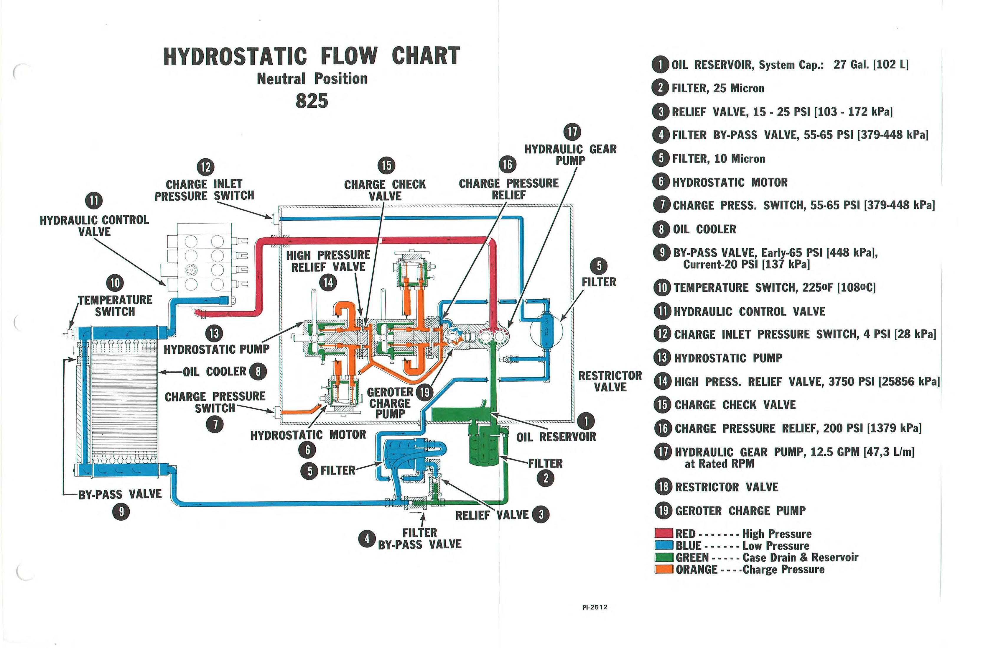
The hydrostatic system is made up of a charge pump (geroter), two hydrostatic pumps and two hydrostatic motors. See the colored Flow Charts PI–02512, PI–02513 and System Operation description for the full operation the Hydrostatic System.
3–2
3–3 CONTROL LINKAGE
3–3.1 Adjustment Of Steering Linkage
1.Lift and block loader so all wheels are off floor, or pull out transmission gear box levers (Fig. 3–10).
2.Tilt ROPS and remove transmission cover.
3.Disconnect linkage from levers on pump assembly (Fig. 3–2).
4.Lower ROPS.
5.Start engine and run at full RPM. Levers will automatically go to neutral. Make sure that levers are not loose on pintle shafts in pumps.
6.Put steering levers in neutral position.
7.Loosen lock nut and turn swivel linkage rod until eye of swivel is in alignment with bolt in pump arm.
8.When alignment is correct, fasten swivel with bolt and tighten lock nut on swivel. Tighten nut for swivel bolt to 10 ft.–lbs. (14 Nm) torque.
9.Install a new gasket before putting transmission cover on.
3–4 ADJUSTMENT OF SPEED RANGE LINKAGE
Adjustment of length of linkage rod (Fig. 3–3, Item 1) must be correct to give equal travel of control lever (Fig. 3–3, Item 2) between high and low range.
There is no other adjustment of the speed range linkage.
If wheel RPM is different between left and right side of loader, first check for correct adjustment of the steering control linkage. (Control lever travel, equal from vertical (center) position to low and high ranges.) If wheel RPM between sides is within 20%, no adjustment is necessary.
Also check for loose bolts on linkage bar and motor control arms. Check for hose or tubelines in wrong position and stopping movement of linkage.
To remove speed–range linkage:
1.Remove the bolt holding the linkage to the arm on the rear motor (Fig. 3–4).
2.Remove the bolts holding the linkage to the arm of the front motor and bellcrank (Fig. 3–5).
3.Remove the bolts holding the bellcrank and linkage rod (Fig. 3–3, Item 3).
4.Remove nuts (Fig. 3–3, Items 4 & 5), control arm (Item 6) and control lever (Item 2).
3–5 STEERING CONTROL LINKAGE
3–5.1 Removal
1.Tilt or remove ROPS (See Section 5–2).
2.Lift the lift arms and install the cylinder support.
3.Clean the area thoroughly.
4.Remove the brake if equipped.
5.Remove the steering levers (Fig. 3–6).
6.Disconnect linkage.
7.Loosen the support nuts (Fig. 3–7).
8.Slide left hand shaft over to welded bracket.
9.Remove left hand support nut.
10.Remove left hand rod.
11.Remove right hand supportnut.
12.Raise left hand end of shaft and remove assembly from transmission (Fig. 3–8).
25 – 28 ft.–lbs. (34 – 38 Nm)
100 – 120 ft.–lbs. (136 – 162 Nm)
25 – 28 ft.–lbs. (34 – 38 Nm)
50 – 70 ft.–lbs. (68 – 94 Nm)
10 – 15 ft.–lbs. (14 – 20 Nm)
25 – 28 ft.–lbs. (34 – 38 Nm)
NOTE:Put LOCTITE sealant on the threads of the bolts for the pintle levers during assembly.
Use the above procedure in reverse order to install the steering linkage. See figure 3–8.1 for the correct torque.
NOTE:All 825 Bobcat loaders between serial number B–1000 and C–1000 have a spacer inside the steering levers (Fig. 3–8.2, Item 1). The spacers must be in place or the levers will not operate correctly.
180 – 200 in.–lbs. (21 – 23 Nm)
3–6 CHECKING HYDROSTATIC SYSTEM
3–6.1 Test Kit
1.0 – 300 PSI gauge.
2.200 PSI pressure gauge
3–6.2 Charge Pressure Check
Steering Levers In Neutral Position:
1.Remove the sending unit from the right rear of the tank and install 0–300 PSI pressure gauge (Fig. 3–9).
2.Correct charge pressure (at idle RPM) is 90 PSI (620 kPa).
Steering Levers in Stroked Position (Forward and Reverse):
1.Remove the oil sender unit from the right rearof the tank (Fig. 3–11, Item 1).
2.Install a gauge with approximately 4 foot hose (101,6 mm) in location shown in Figure 3–11, Item 1 ).
3.Push transmission levers in (Fig. 3–10).
4.Lower the ROPS. Position the hose so it will not be damaged (pinched) when lowering the ROPS.
5.Fasten the gauge to the side of the ROPS so it can be seen when operating the Bobcat.
6.Install the ROPS bolts and tighten.
7.Operate the machine under load at full RPM and check pressure on the gauge. 100 PSI (689 kPa) is the minimum acceptable reading.
3–6.3 Charge Pump Inlet Pressure
Steering Levers in Neutral Position:
1.Install 200 PSI gauge at the left rear of the frame (Fig. 3–11, Item 2).
2.Pull out the transmission gear box levers (Fig. 3–10).
3.Start the engine and run at full RPM.
4.Normal charge inlet pressure is 15–20 PSI (103–138 kPa). Minimum charge inlet pressure is 4 PSI (28 kPa).
3–7 CHECKING RELIEF VALVES
3–7.1 Charge Relief Valve
NOTE:See Bobcat Technical Information Bulletin #162 for more information on the Charge Relief Valve.
To check condition of charge relief valve it must be removed from unit and visual inspection made as follows:
1.Remove inlet line to charge pump.
2.Use a screwdriver and compress spring.
3.Use snap ring pliers to remove snap ring.
4.Remove spacer, spring and poppet (Fig. 3–12).
Reverse the above to install.
NOTE:Put clean grease on poppet to help hold to spring during installation.
3–7.2 Filter Relief Valve (Fig. 3–13)
1.Disconnect tubelines and remove valve from unit.
2.Connect compressed air line to each end of valve to see if air goes through.
3.Air must go only one way.
3–7.3 Charge Inlet Relief Valve (Fig. 3–13).
1.Disconnect tubelines and remove valve from unit.
2.Connect air hose to each end to see if air goes through.
3.Air must go only one way.
3–7.4 High Pressure Relief Valve
1.Lift the lift arms and install cylinder stop on lift cylinder (Fig. 3–14).
2.Tilt ROPS forward.
3.Clean transmission housing area.
4.Remove transmission cover.
5.Remove valves and exchange valves from one side to the other (Fig. 3–15).
6.If the drive system problem is now on other side, make replacement of valve with defect.
3–8 10 MICRON FINAL FILTER ELEMENT REPLACEMENT (Fig. 3–16)
1.Lift the lift arms and install cylinder stop on lift cylinder (Fig. 3–14).
2.Remove steering levers by removing bolts and hitting with hammer to force lever off.
3.Activate tilt switch and tilt cab all the way forward.
4.Attach overhead hoist to ROPS and take up all loose play.
5.Remove bolt which fastens tilt assembly to ROPS.
6.Tilt ROPS fully forward and hold in position with a support.
7.Disconnect linkage rods and remove pedal assembly.
NOTE:CLEAN LOADER FLOOR AREA THOROUGHLY (Transmission Housing).
8.Remove floor plate.
9.Remove the final filter element.
10.Install new 10 micron element. Tighten it hand tight.
3–9 TEMPERATURE AND PRESSURE SWITCHES
The hydrostatic warning system is made up of 2 pressure sending switches (charge pressure and charge pump inlet pressure) and one temperature sending switch (See Fig. 3–1).
The charge pressure switch (1) is set to activate when pressure goes below 65 PSI.
The charge pump inlet switch (2) is set to activate when pressure goes below 4 PSI.
The temperature inlet switch is set to activate when temperature goes above 210°F (99°C).
3–10 REMOVAL OF HYDROSTATIC PUMP ASSEMBLY
1.Tilt or remove ROPS (See Section 5–2).
2.Lift the lift arms and install cylinder stops (Fig. 3–14).
3.Steam clean the loader thoroughly.
4.Remove fluid from transmission and remove the transmission housing cover.
5.Remove all hoses from fittings on pump assembly (Figs. 3–17 & 3–18). Protect ends of hoses with plastic bags. Put caps on open fittings (Fig. 3–20).
6.Disconnect steering linkage from pump assembly (Fig. 3–19).
7.Remove front support bolt (Fig. 3–20).
8.Remove fastening bolts and remove the pump assembly (Fig. 3–21). Weight of pump assembly is 80 pounds.
3–11 INSTALLING HYDROSTATIC PUMP
1.Make alignment of pump drive (spline) shaft and fasten pump assembly to transmission housing with two bolts.
2.Install front support bolt (Fig. 3–20).
3.Connect steering linkage to pump control arms.
4.Connect hoses.
5.Install new cover and gasket.
3–12 REMOVAL OF HYDROSTATIC MOTOR
1.Tilt or remove ROPS (See Section 5–2).
2.Lift the lift arms and install cylinder stops (Fig. 3–14).
3.Steam clean the loader thoroughly.
4.Remove fluid from transmission and remove the transmission housing cover.
5.Remove the pump assembly.
6.Disconnect 2 speed linkage (Fig. 3–22).
7.Remove hoses and elbows when removing right hand motor.
8.Remove 2 bolts which hold the motor to reduction gearhousing (Fig. 3–23).
9.Remove the motor. Weight is 22 pounds.
3–13 INSTALLING HYDROSTATIC MOTOR
1.Install elbows and hoses (right hand motor) (Fig. 3–23a).
2.Install motor in reduction housing and fasten with bolts.
3.Connect 2 speed linkage to control arm on motor.
3–13.1 New Hydrostatic Pump & Motor
825 Bobcats 14001 & Up have new hydrostatic pumps and motors. Old style pump and motors are no longer available. Conversion kits are available to change the old units to the new, better units and are listed in the 825 Parts Book. Check to see which unit you have by checking the letters on the pump (Fig. 3–23b).
Old Style – Letters New Style – Letters
Front Pump – RAB
Rear Pump RAA
Front Pump – RCB
Rear Pump – RCA
Motor – DAG or DAZ Motor – DBA
When hydrostatic units have been changed they must be marked to show the change.