28 minute read
OPERATOR SAFETY WARNINGS


Warning
Operator must have instructions before running the machine. Untrained operators can cause injury or death.
W-2001-1285
Safety Alert Symbol:This symbol with a warning statement, means: “Warning, be alert! Your safety is involved!” Carefully read the message that follows.
Never use the loader without instructions. See machine signs (decals), Operation & Maintenance Manual, and Operator’s Handbook.
Always use the seat bar and fasten seat belt snugly. Always keep feet on the foot pedals or foot rest when operating loader.
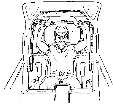
Never use loader without operator cab with ROPS and FOPS approval. Fasten your seat belt.
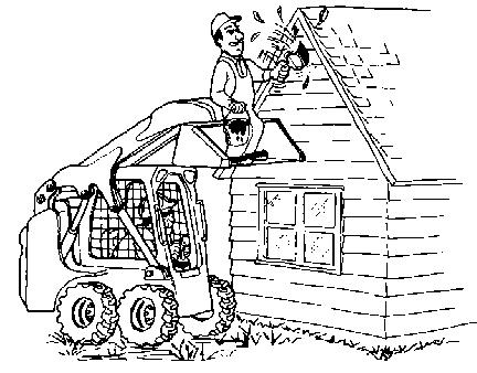
Never use loader as man lift or elevating device for personnel.
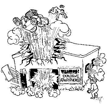
Do not use loader in atmosphere with explosive dust, explosive gas, or where exhaust can contact flammable material.
Never carry riders. Keep bystanders away from work area.
Always carry bucket or attachments as low as possible. Do not travel or turn with lift arms up. Load, unload, and turn on flat level ground.
Never exceed Rated Operating Capacity.
Never leave loader with engine running or with lift arms up. To park, engage parking brake and put attachment flat on the ground.
Safety Equipment
Never modify equipment. Use only attachments approved by Bobcat Company for this model loader.
The Bobcat Loader must be equipped with safety items necessary for each job. Ask your dealer about attachments and accessories.
1.SEAT BELT: Check belt fasteners and check for damaged webbing or buckle.
2.SEAT BAR: When up, it must lock the loader controls.
3.OPERATOR CAB (ROPS and FOPS): It must be on the loader with all fasteners tight.
4.HANDBOOK: Must be in the cab.

5.SAFETY SIGNS (DECALS): Replace if damaged.
6.SAFETY TREADS: Replace if damaged.
7.GRAB HANDLES: Replace if damaged.
8.LIFT ARM SUPPORT DEVICE: Replace if damaged.
9.PARKING BRAKE
10. BOBCAT INTERLOCK CONTROL SYSTEM (BICS)

REFERENCE INFORMATION
Write the correct information for YOUR Bobcat Loader in the spaces below. Always use these numbers when referring to your Bobcat Loader.
NOTES:
YOUR BOBCAT DEALER:
ADDRESS:
PHONE:
Bobcat Company
P.O. Box 128
Gwinner, ND 58040-0128
Bobcat Company Europe
Dréve Richelle
B-1410 WATERLOO
Belgium
Foreword
This Operation & Maintenance Manual was written to give the owner/operator instructions on the safe operation and maintenance of the Bobcat Loader. READ AND UNDERSTAND THIS OPERATION & MAINTENANCE MANUAL BEFORE OPERATING YOUR Bobcat Loader. If you have any questions, see your Bobcat dealer.
BOBCAT COMPANY IS ISO 9001:2000 CERTIFIED
ISO 9001:2000 is a set of international standards that control the processes and procedures which we use to design, develop, manufacture, distribute, and service Bobcat products.
British Standards Institute (BSI) is the Certified Registrar Bobcat chose to assess the Company’s compliance with the ISO 9001:2000 set of standards. The BSI registration certifies that the two Bobcat manufacturing plants and the Bobcat corporate offices (Gwinner, Bismarck & West Fargo) in North Dakota are in compliance with ISO 9001:2000. Only certified assessors, like BSI, can grant registrations.
ISO 9001:2000 means that as a company we say what we do and do what we say. In other words, we have established procedures and policies, and we provide evidence that the procedures and policies are followed.
California Proposition 65 Warning
Diesel engine exhaust and some of its constituents are known to the State of California to cause cancer, birth defects and other reproductive harm.
Regular Maintenance Items
FILTER, Inner
HYDROSTATIC FILTER
HYDROSTATIC FILTER, In-Line
FLUID, Hydraulic/Hydrostatic (5 Gallons)
- One 5 Gal. container
RADIATOR CAP 6672491 (773G)
6646678 (773)
Propylene Glycol Anti-Freeze Premixed - 6724094 Concentrate - 6724354
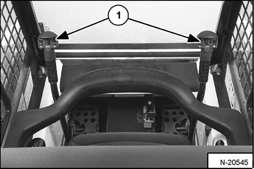
Serial Number Locations
Always use the serial number of the loader when requesting service information or when ordering parts. Early or later models (identification made by serial number) may use different parts, or it may be necessary to use a different procedure in doing a specific service operation.
Engine Serial Number

Figure 2
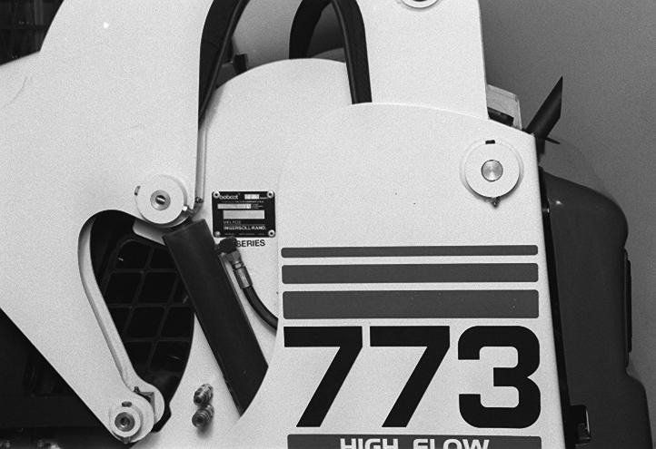
Loader Serial Number
The loader serial number plate is located on the outside of the loader frame [Figure 1]
Explanation of loader Serial Number:
XXXX XXXXX
Module 2. - Production Sequence (Series)
Module 1. - Model / Engine Combination
1. The four digit Model/Engine Combination Module number identifies the model number and engine combination.
2. The five digit Production Sequence Number identifies the order which the loader is produced.
Delivery Report
Figure 3
The delivery report must be filled out by the dealer and signed by the owner or operator when the Bobcat Loader is delivered. An explanation of the form must be given to the owner. Make sure it is filled out completely [Figure 3].
BOBCAT LOADER IDENTIFICATION
FRONT LIGHTS
OPERATOR SEAT WITH SEAT BELT
SEAT BAR
GRAB HANDLES
STEERING LEVER
TILT CYLINDER
BUCKET
BUCKET STEPS
LIFT ARM LINK
REAR GRILL
TAIL LIGHT
REAR WINDOW
REAR AUXILIARY QUICK COUPLERS
STABILIZER ROD
FRONT AUXILIARY QUICK COUPLERS
SAFETY TREAD
OPERATOR CAB (ROPS & FOPS)
LIFT ARM
LIFT CYLINDER
LIFT ARM SUPPORT DEVICE
REAR LIGHT
REAR DOOR
OPTIONAL OR FIELD ACCESSORY (Not Standard Equipment)
* TIRES
B-15516
B-16275
* TIRES - The Bobcat Loader is factory equipped with heavy duty flotation tires. See Specifications Section and your Bobcat dealer for available tires.
† BUCKET - Several different buckets and other attachments are available for the Bobcat Loader.
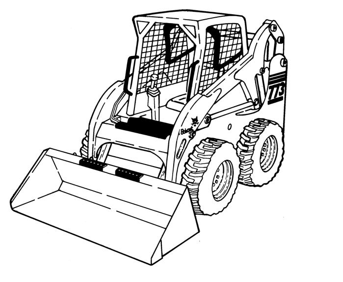
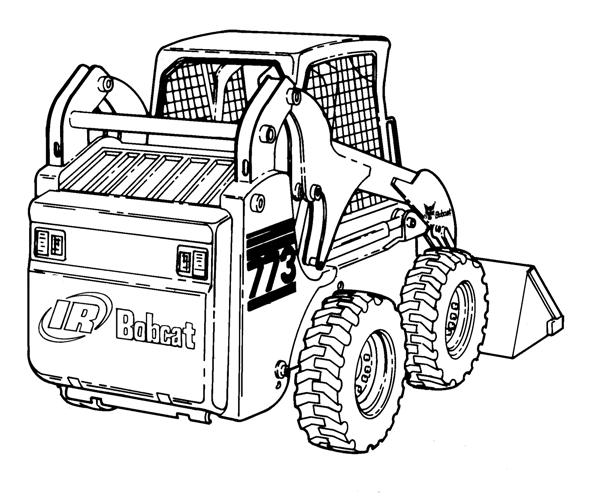
ROPS, FOPS - Roll Over Protective Structure per SAE J1040 and ISO 3471, and Falling Object Protective Structure per SAE J1043 and ISO 3449, Level I. Level II is available. The Bobcat Loader is base-equipped with a standard operator cab as shown. Extra insulated cab is available as an option (Reduced noise level).
773, 773H Bobcat Loader
FEATURES, ACCESSORIES, AND ATTACHMENTS
Model 773, 773T, 773T-500K Bobcat Loaders are equipped with the following standard items:
Adjustable Cushion Seat
Automatically Activated Glow Plugs
Auxiliary Hydraulics: Variable Flow / Maximum Flow
Bob-Tach
Power Bob-Tach (773T-500K Only)
Bobcat Interlock Control System (BICS™)
Dual Path Cooling System
Engine/Hydraulic System Shutdown
Instrumentation: Hourmeter Engine Temperature and Fuel Gauges and Warning Lights
Lift Arm Support Device
Lights, Front and Rear
Operator Cab (ROPS & FOPS)
Operator Cab, Deluxe - With Heater & A/C (773T-500K Only)
Parking Brake
Seat Bar
Seat Belt
Spark Arrestor Exhaust System
Tires773, 773T (10-16.5 Bobcat Heavy Duty, 8 Ply Rating)
773T - 500K Series (31.5 x 13-16.5 Galaxy Hippo, 10 Ply Rating)
Turbo-Charger
Below is a list of some equipment available from your Bobcat Loader dealer as Dealer and / or Factory Installed Accessories and Factory Installed Options. See your Bobcat dealer for other available options, accessories and attachments.
Accessory Wire Harness
Advanced Control System (ACS) (Selectable Foot Pedal or Hand Control)
Advanced Hand Controls
Air Conditioned Cab (Not 773)
Attachment Control Device (ACD)
Back-up Alarm
Catalytic Exhaust Purifier
Cab Enclosure Kit
Cab Enclosure (Vinyl)
Counterweight Kit
Cover Kit (Pedal / Footrest Area)
Standard Cab Kit
Deluxe Sound Cab
Deluxe Suspension Seat
Deluxe Instrumentation (With Keyless Start)
Dual Attachment Control Kit
Engine Heater
Fire Extinguisher
FOPS Kit (Level II)
Front Door Kit
Heater Kit
Horn
Hydraulic Bucket Positioning (Includes On/Off Selection)
Lift Kit(s)
Locking Fuel Cap
Power Bob-Tach (Std. on 500K Series)
Radiator Screen Kit
Rear Auxiliary Hydraulics
Rear Window Wiper
Side Window Kit
Seat Belt with 3-Point Restraint
Seat Belt - 3 inch Wide
Special Applications Kit
Tailgate Lock
Tires
Ultra Grip Tread
Flotation
Solid
Top and Rear Cab Windows
Warning Lights
Four-Way Flasher (Includes Direction Signals)
Rotating Beacon
Strobe Light
Weighlog Kit
Specifications subject to change without notice
773, 773H Bobcat Loader
FEATURES, ACCESSORIES, AND ATTACHMENTS (CONT’D)
These and other attachments are approved for use on this model loader. Do not use unapproved attachments. Attachments not manufactured by Bobcat may not be approved.
The versatile Bobcat Loader quickly turns into a multi-job machine with a tight-fit attachment hook-up . . . from bucket to grapple to pallet fork to backhoe and a variety of other attachments.
See your Bobcat dealer for more details on these and other attachments and field accessories.
Increase the versatility of your Bobcat Loader with a variety of bucket styles and sizes.
Buckets Available
Many bucket styles, widths and different capacities are available for a variety of different applications. They include Construction & Industry, Low profile, Fertilizer and Snow, to name a few. See your Bobcat dealer for the correct bucket for your Bobcat Loader and application.
Attachments
•3-Point Hitch
•Angle Broom
•Auger
•Backhoe
•Box Blade
•Bucket Adapter
•Snow Blade
•V-Blade
•Dozer
•Breaker
•Buckets
•Combination Bucket
•Chipper
•Concrete Mixer
•Concrete Pump
•Cutter Crusher
•Digger
•Box Blade
•Dumping Hopper
•Finish Mower
•Grader
•Industrial Bucket Grapple
•Industrial Fork Grapple
•Landplane
•Landscape Rake
•Pallet Fork
•Planer
•Rear Stabilizers
•Rotary Cutter
•Scarifier
•Scraper
•Snow Blower
•Sod Layer
•Soil Conditioner
•Spreader
•Stabilizers
•Sweeper
•Stump Grinder
•Tiller
•Tilt-Tatch
•Tracks
•Trench Compactor
•Trencher
•Utility Fork
•Utility / Farm Grapple
•Vibratory Roller
•Water Kit
•Wheel Saw
SAFETY INSTRUCTIONS Before Operation
Carefully follow the operating and maintenance instructions in this manual.
The Bobcat Loader is highly maneuverable and compact. It is rugged and useful under a wide variety of conditions. This presents an operator with hazards associated with off highway, rough terrain applications, common with Bobcat Loader usage.
The Bobcat Loader has an internal combustion engine with resultant heat and exhaust. All exhaust gasses can kill or cause illness so use the Loader with adequate ventilation.
The dealer explains the capabilities and restrictions of the Bobcat Loader and attachment for each application. The dealer demonstrates the safe operation according to Bobcat instructional materials, which are also available to operators. The dealer can also identify unsafe modifications or use of unapproved attachments. The attachments and buckets are designed for a Rated Operating Capacity (some have restricted lift heights). They are designed for secure fastening to the Bobcat Loader. The user must check with the dealer, or Bobcat literature, to determine safe loads of materials of specified densities for the machine - attachment combination.
The following publications and training materials provide information on the safe use and maintenance of the Bobcat machine and attachments:
•The Delivery Report is used to assure that complete instructions have been given to the new owner and that the machine and attachment is in safe operating condition.
•The Operation & Maintenance Manual delivered with the machine or attachment gives operating information as well as routine maintenance and service procedures. It is a part of the machine and can be stored in a container provided on the machine. Replacement Operation & Maintenance Manuals can be ordered from your Bobcat dealer.
•Machine signs (decals) instruct on the safe operation and care of your Bobcat machine or attachment. The signs and their locations are shown in the Operation & Maintenance Manual. Replacement signs are available from your Bobcat dealer.
•An Operator’s Handbook is fastened to the operator cab of the Loader. It’s brief instructions are convenient to the operator. The Handbook is available from your dealer in an English edition or one of many other languages. See your Bobcat dealer for more information on translated versions.
•The AEM Safety Manual delivered with the machine gives general safety information.
•The Skid-Steer Loader Operating Training Course is available through your Bobcat dealer. This course is intended to provide rules and practices of correct operation of the Bobcat Loader. The course is available in English and Spanish versions.
•Service Safety Training Courses are available from your Bobcat dealer. They provide information for safe and correct service procedures.
•See the PUBLICATIONS AND TRAINING RESOURCES Page in this manual or your Bobcat dealer for Service and Parts Manuals, printed materials, videos, or training courses available. Also check the Bobcat web sites www.training.bobcat.com or www.bobcat.com
The dealer and owner/operator review the recommended uses of the product when delivered. If the owner/operator will be using the machine for a different application(s) he or she must ask the dealer for recommendations on the new use.
1-888-258-0808
When you call, you will be directed to a location in your state/city for information about buried lines (telephone, cable TV, water, sewer, gas, etc.)
SAFETY INSTRUCTIONS (CONT’D)
Safe Operation Is The Operator’s Responsibility
Safety Alert Symbol
This symbol with a warning statement means: “Warning, be alert! Your safety is involved!” Carefully read the message that follows.
Warning
Operator must have instructions before running the machine. Untrained operators can cause injury or death.
W-2001-1285
Important
This notice identifies procedures which must be followed to avoid damage to the machine.
I-2019-0284
Warning
Warnings on the machine and in the manuals are for your safety. Failure to obey warnings can cause injury or death.
W-2044-1285
The Bobcat Loader and attachment must be in good operating condition before use.
Check all of the items on the Bobcat Service Schedule Decal under the 8-10 hour column or as shown in the Operation & Maintenance Manual.
Safe Operation Needs A Qualified Operator
For an operator to be qualified, he or she must not use drugs or alcoholic drinks which impair alertness or coordination while working. An operator who is taking prescription drugs must get medical advice to determine if he or she can safely operate a machine.
A Qualified Operator Must Do The Following:
Understand the Written Instructions, Rules and Regulations
•The written instructions from Bobcat Company include the Delivery Report, Operation & Maintenance Manual, Operator’s Handbook, Safety Manual and machine signs (decals).
•Check the rules and regulations at your location. The rules may include an employer’s work safety requirements. Regulations may apply to local driving requirements or use of a Slow Moving Vehicle (SMV) emblem. Regulations may identify a hazard such as a utility line.
Have Training with Actual Operation
•Operator training must consist of a demonstration and verbal instruction. This training is given by your Bobcat dealer before the product is delivered.
•The new operator must start in an area without bystanders and use all the controls until he or she can operate the machine and attachment safely under all conditions of the work area. Always fasten seat belt before operating.
•Operator Training Courses are available from your Bobcat dealer in English and Spanish. They provide information for safe and efficient equipment operation. Safety videos are also available.
•Service Safety Training Courses are available from your Bobcat dealer. They provide information for safe and correct service procedures.
Know the Work Conditions
•Know the weight of the materials being handled. Avoid exceeding the Rated Operating Capacity (R.O.C.) of the machine. Material which is very dense will be heavier than the same volume of less dense material. Reduce the size of the load if handling dense material.
•The operator must know any prohibited uses or work areas, for example, he or she needs to know about excessive slopes.
•Know the location of any underground lines. Call local utilities or the TOLL FREE phone number found in the Before Operation Section of this manual.
•Wear tight fitting clothing. Always wear safety glasses when doing maintenance or service. Safety glasses, hearing protection or Special Applications Kits are required for some work. See your Bobcat dealer about Bobcat Safety Equipment for your model.
SI SSL-0206
SAFETY INSTRUCTIONS (CONT’D)
Fire Prevention
The machines and some attachments have components that are at high temperatures under normal operating conditions. The primary source of high temperatures is the engine and exhaust system. The electrical system, if damaged or incorrectly maintained, can be a source of arcs or sparks.
Flammable debris (leaves, straw, etc.) must be removed regularly. If flammable debris is allowed to accumulate, it can cause a fire hazard. Clean often to avoid this accumulation. Flammable debris in the engine compartment is a potential fire hazard.
The spark arrestor exhaust system is designed to control the emission of hot particles from the engine and exhaust system, but the muffler and the exhaust gases are still hot.
•Do not use the machine where exhaust, arcs, sparks or hot components can contact flammable material, explosive dust or gases.
•The operator cab, engine compartment and engine cooling system must be inspected every day and cleaned if necessary to prevent fire hazards and overheating.
•Check all electrical wiring and connections for damage. Keep the battery terminals clean and tight. Repair or replace any damaged part.
•Check fuel and hydraulic tubes, hoses and fittings for damage and leakage. Never use open flame or bare skin to check for leaks. Tighten or replace any parts that show leakage. Always clean fluid spills. Do not use gasoline or diesel fuel for cleaning parts. Use commercial nonflammable solvents.
•Do not use ether or starting fluids on any engine that has glow plugs. These starting aids can cause explosion and injure you or bystanders.
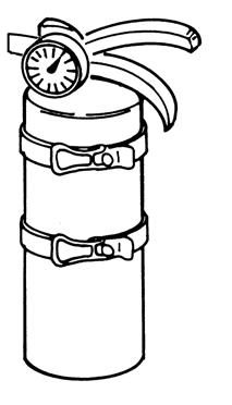
•Always clean the machine, disconnect the battery, and disconnect the wiring from the Bobcat controllers before welding. Cover rubber hoses, battery and all other flammable parts. Keep a fire extinguisher near the machine when welding. Have good ventilation when grinding or welding painted parts. Wear dust mask when grinding painted parts. Toxic dust or gas can be produced.
•Stop the engine and let it cool before adding fuel. No smoking!
•Use the procedure in the Operation & Maintenance
Manual for connecting the battery and for jump starting.
•Use the procedure in the Operation & Maintenance Manual for cleaning the spark arrestor muffler (if equipped).
•Know where fire extinguishers and first aid kits are located and how to use them. Fire extinguishers are available from your Bobcat dealer [Figure 1]
MACHINE SIGNS (DECALS)
Follow the instructions on all the Machine Signs (Decals) that are on the loader. Replace any damaged machine signs and be sure they are in the correct locations. Machine signs are available from your Bobcat Loader dealer.
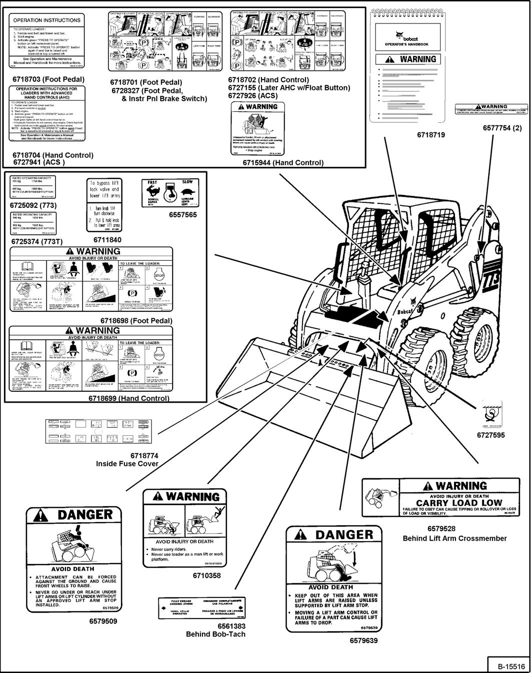
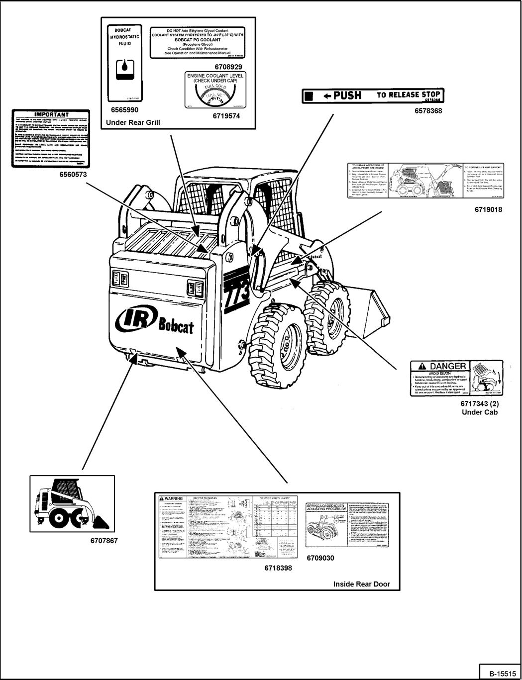
MACHINE SIGNS (DECALS) (CONT’D)
Follow the instructions on all the Machine Signs (Decals) that are on the loader. Replace any damaged machine signs and be sure they are in the correct locations. Machine signs are available from your Bobcat Loader dealer.
Instrument Panel Identification
Figure OI-1
Left Panel - Standard and Deluxe Instrument Panels
The left instrument panel [Figure OI-1] is the same for both Standard and the Deluxe Instrument Panels (Option).
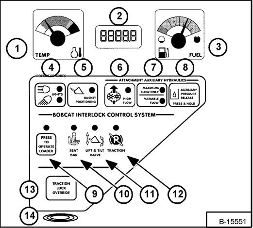
The table below shows the DESCRIPTION and FUNCTION / OPERATION for each of the components of the left panel.
REF NO DESCRIPTION FUNCTION / OPERATION
1TEMPERATURE GAUGE Shows the engine coolant temperature.
2HOURMETER / CODE DISPLAY / GLOW PLUG COUNTDOWN
HOURMETER - Records operating hours of loader. CODE DISPLAY - Displays alphanumeric SERVICE
CODES* relating to the loader monitoring system. COUNTDOWN - Glow Plug time remaining.
3FUEL GAUGE Shows the amount of fuel in the tank.
4LIGHTS / HOLD FOR CODES LIGHTS - Press once for FRONT LIGHTS. Press a second time for FRONT AND REAR lights. Press a third time to turn all lights off. HOLD FOR CODES - Press and hold two seconds for display of SERVICE CODES* (Item 2). (CODES* show only when there is an error found by loader monitoring system.)
5BUCKET POSITIONING (BP) (Option) Press to engage BP function. Press again to disengage. Press & hold 2 seconds to view BASE or Shtdn ( SHUTDOWN) feature in HOURMETER / CODE DSIPLAY. Also shows Operational Code Number.
ATTACHMENT AUXILIARY HYDRAULICS
6HIGH FLOW (Option) Press to engage the HIGH FLOW auxiliary hydraulics. Press again to disengage.
7MAXIMUM FLOW / VARIABLE FLOWPress once to engage the VARIABLE FLOW auxiliary hydraulics. Press a second time to engage MAXIMUM FLOW. Press a third time to disengage all auxiliary hydraulics. [VARIABLE FLOW allows for slow-to-fast movement of auxiliary functions (The farther you move the switch, the faster the movement of auxiliary functions.) MAXIMUM FLOW allows for only fast movement.]
8AUXILIARY PRESSURE RELEASEPress and hold for two seconds. The engine will stop. Auxiliary circuit hydraulic pressure will be released. Turn key OFF (Standard Panel); or press STOP Button (Deluxe Panel)
BOBCAT INTERLOCK CONTROL SYSTEM (BICS™) (See SYSTEM SETUP AND ANALYSIS, Page 73 for troubleshooting BICS™)
9PRESS TO OPERATE LOADERPress to activate BICS® System when the Seat Bar is down and operator is seated in operating position.
10SEAT BAR
11LIFT & TILT VALVE
12TRACTION
The light comes ON when the seat bar is down.
The light comes ON when the seat bar is down and the PRESS TO OPERATE Button is pressed. The lift and tilt functions can be operated when the light is ON
The light comes ON when the seat bar is down, engine is r unning, and parking brake is released. The loader can be moved forward or backward when the light is ON
13TRACTION LOCK OVERRIDE (Functions Only When Seat Bar Is Raised And The Engine Is Running) Press to unlock the brakes. Allows you to use the steering levers to move the loader forward or backward when using the backhoe attachment or for loader service. (See “TRACTION LOCK OVERRIDE” on page8). Press a second time to lock the brakes.
14ALARMThe ALARM beeps when there is an Error, WARNING or ◆SHUTDOWN condition.
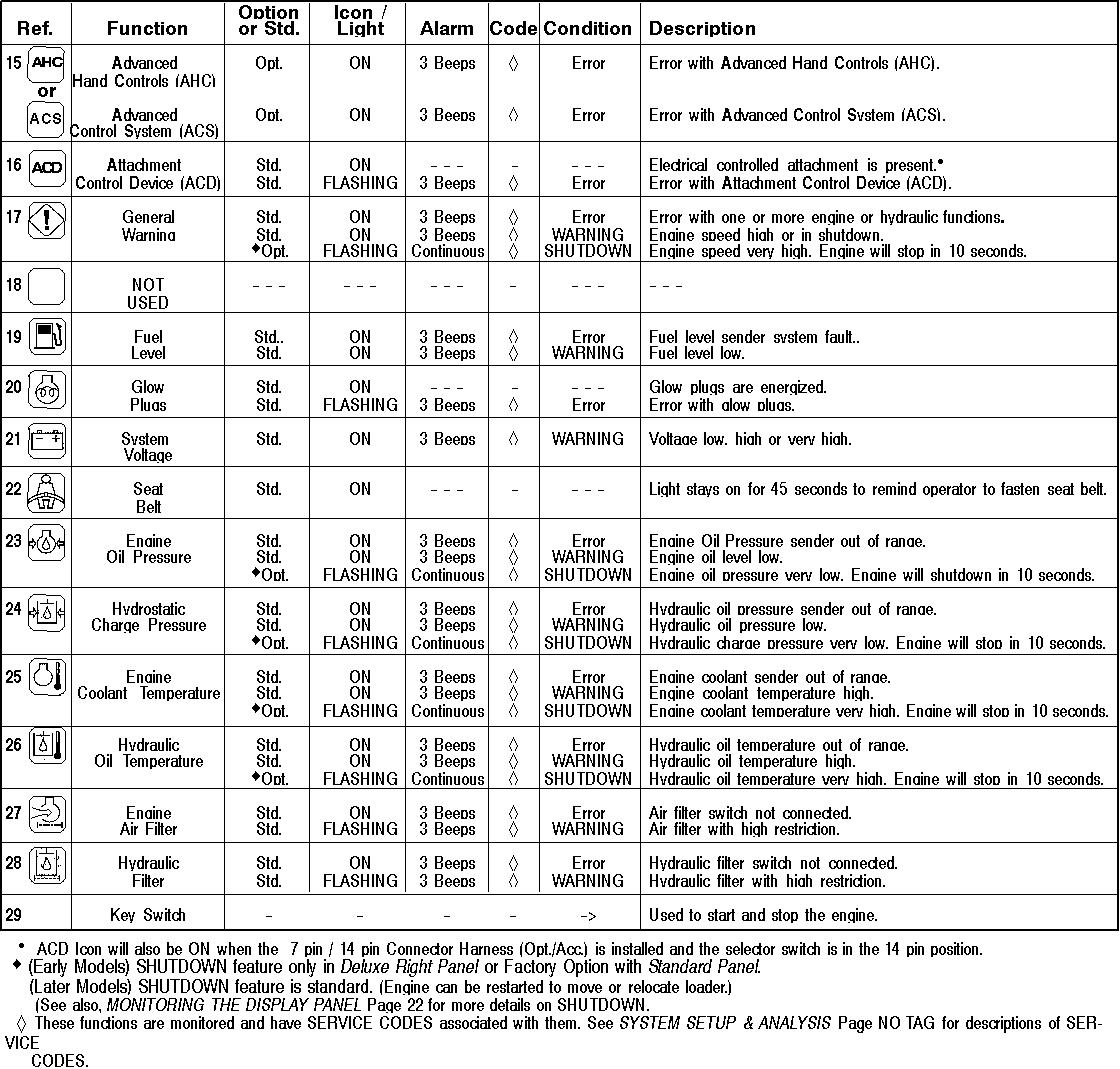
* See SYSTEM SETUP & ANALYSIS, Page 73 for further description of SERVICE CODES. (Early Models) SHUTDOWN feature only in Deluxe Right Panel or Factory Option with Standard Panel (Later Models) SHUTDOWN feature is standard.
INSTRUMENT PANEL IDENTIFICATION (CONT’D)
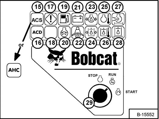
Right Panel - Standard Instrument Panel (With Key Switch)
The right instrument panel shown [Figure OI-2] is the Standard Panel
The table below shows the Icons and other components of the Right Standard Panel
INSTRUMENT PANEL IDENTIFICATION (CONT’D)
Right Panel - Deluxe Instrument Panel (With Keyless Start)
Figure OI-3
1.Display Panel: The Display Panel [Figure OI-3] is where all system setup, monitoring, troubleshooting, and error conditions are displayed.
2.Function Icons: The lower left area of the Deluxe Panel has the same Icons as the Standard Panel (See Page 4). These Icons are only visible when the monitoring system has detected an error.
3.Selection Buttons: The four Selection Buttons allow you to select items from the Display Panel and scroll through screens.
4.Keypad: The numeric keypad (Item 4) [Figure OI-3] has two functions:
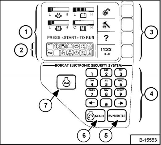
(a) To enter a number code (password) to allow starting the engine (Keyless Start).
(b) To enter a number as directed for further use of the Display Panel.
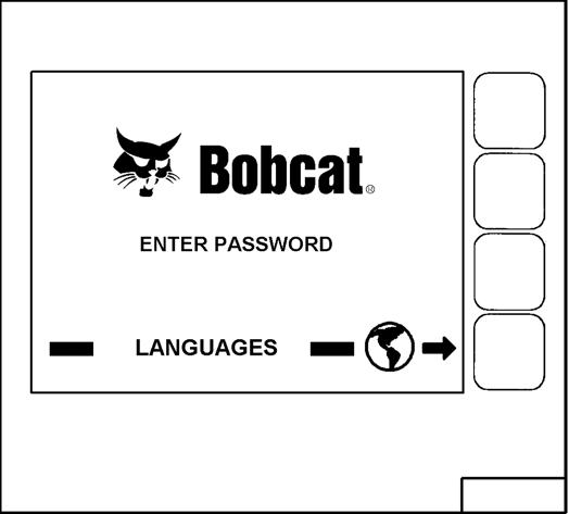
Figure OI-4
The first screen you will see on your new loader will be as shown in [Figure OI-4]
When this screen is on the display you can enter the password and start the engine or change the Display Panel setup features.
NOTE: Loaders with Deluxe Instrument Panel have a permanent, randomly generated Master Password set at the factory. Your loader will be assigned an Owner Password. Your dealer will provide you with this password. Change the password to one that you will easily remember to prevent unauthorized use of your loader. (See Passwords (Deluxe) on Page SA9.) Keep your password in a safe place for future needs.
Start Engine: Use the Keypad to enter the numbers (letters) of your password and press the RUN / ENTER key (Item 5) [Figure OI-3]
Press and hold the START Button (Item 6) [Figure OI-3] until the engine starts. (Always preform the PRESTARTING PROCEDURE, Page 17 before starting the engine.)
Press the STOP Button (Item 7) [Figure OI-3] to stop the engine.
Change Language: Press the Selection Button at the end of the arrow [Figure OI-4] to go to the next screen.
INSTRUMENT PANEL IDENTIFICATION (CONT’D)
Right Panel - Deluxe Instrument Panel (With Keyless Start) (Cont’d)
Figure OI-5
Use the Keypad to select the number of the language [Figure OI-5]

Press EXIT. The screen will return to [Figure OI-4]. You can then enter the password and start the engine.
See Deluxe Panel Setup on Page SA-9, for further description of screens to setup the system for your use.
NOTE: Pressing the EXIT key will go to the previous screen and you can continue pressing until you get to the initial (home) screen.
SHORTCUT: Press the "0" (zero) key to get to the home screen immediately.
INSTRUMENT PANEL IDENTIFICATION (CONT’D)
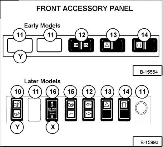
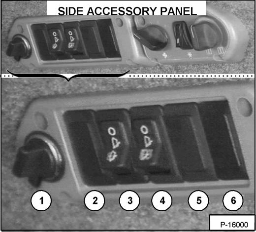
Option and Field Accessory Panels (If Equipped)

5.NOT USED- - -
6.NOT USED- - -
7.FAN MOTORTurn clockwise to increase fan speed; counterclockwise to decrease. There are four positions; OFF - 1 - 2 - 3.
8.AIR CONDITIONIN G Press the top of the switch to start; press the bottom to stop. (Fan switch must be on for A/C to operate).
9.TEMPERATUR E CONTROL Turn clockwise to increase the temperature; counterclockwise to decrease.
REF.
NO. DESCRIPTION FUNCTION / OPERATION
1.POWER PLUGProvides a 12V receptacle for accessories.
2.NOT USED- - -
3.FRONT WIPERPress the top of the switch to start the front wiper (press and hold for washer fluid). Press the bottom of the switch to stop the wiper.
4.REAR WIPERPress the bottom of the switch to start the rear wiper. Press the top of the switch to provide washer fluid to clean the rear window.
REF. NO. DESCRIPTION FUNCTION / OPERATION
10.ADVANCED CONTROL SYSTEM (ACS) (If Equipped)
Press the top to select Hand Controls; bottom to select Foot Controls.
11.NOT USED- - -
12.TURN SIGNAL INDICATORS Indicates left or right TURN SIGNALS are ON.
13.HAZARD LIGHTS Press the left side (or top) to turn the HAZARD LIGHTS ON; right side (or bottom) to turn OFF.
14.ROTATING BEACON Press the left side (or top) to turn the ROTATING BEACON ON; right side (or bottom) to turn OFF.
15.PARKING BRAKE Press the top to engage the PARKING BRAKE; bottom to disengage.
16.POWER BOBTACH (If Equipped) Press and hold the up arrow to disengage the Bob-Tach wedges. Press and hold the down arrow to engage the wedges into the mounting frame holes.
NOTE: Some Later Models may have (ACS) switch (Item 10 above) in position "X" [Figure OI-8] and some may have Power Bob-Tach switch (Item 16 above) in position "Y" [Figure OI-8].
INSTRUMENT PANEL IDENTIFICATION (CONT’D)
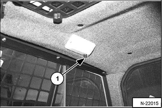
Cab Light
Figure OI-9
Push the button (Item 1) [Figure OI-9] to turn the light ON. Push the button again to turn OFF.
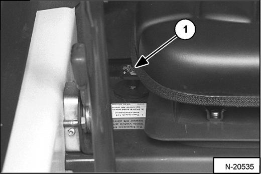
LIFT ARM BY-PASS CONTROL
Figure OI-10
The lift arm by-pass control (Item 1) [Figure OI-10] is used to lower the lift arms if the lift arms cannot be lowered during normal operations.
•Sit in the operator's seat.
•Fasten the seat belt and lower the seat bar.
•Turn the knob (Item 1) [Figure OI-10] clockwise 1/4 turn.
•Pull up and hold the knob until the lift arms slowly lower.
Traction Lock Override
Figure OI-11
(Functions Only When The Seat Bar Is Raised And The Engine Is Running) There is a TRACTION LOCK OVERRIDE Button (Item 1) [Figure OI-11] on the left instrument panel which will allow you to use the steering levers to move the loader forward & backward when using the backhoe attachment or for loader service.
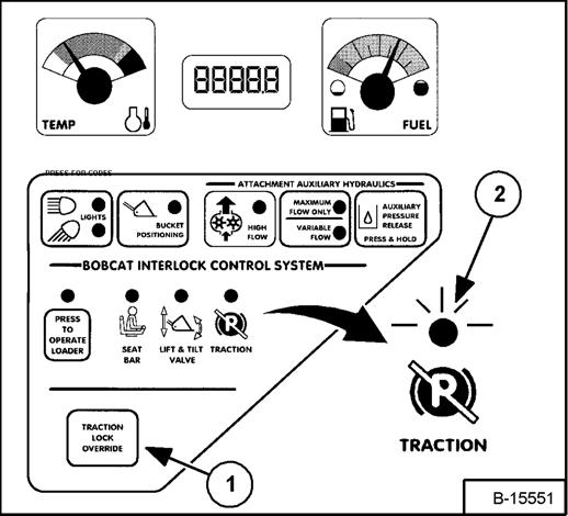
•Press the TRACTION LOCK OVERRIDE Button once to unlock traction drive. The TRACTION light (Item 2) [Figure OI-11] will be ON.
•Press the button a second time to lock the traction drive. The TRACTION light (Item 2) [Figure OI-11] will be OFF.
NOTE: The TRACTION LOCK OVERRIDE Button will unlock the traction drive when seat bar is raised and the engine is running.
The TRACTION LOCK OVERRIDE Button will function if brake pedal is in the engaged or disengaged position and the engine is running.
Engine Speed Control
Figure OI-12
The speed control lever is at the right side of the operator's seat (Item 1) [Figure OI-12]
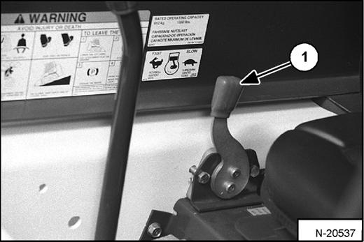
Move the lever forward to increase engine speed. Move backward to decrease engine speed.
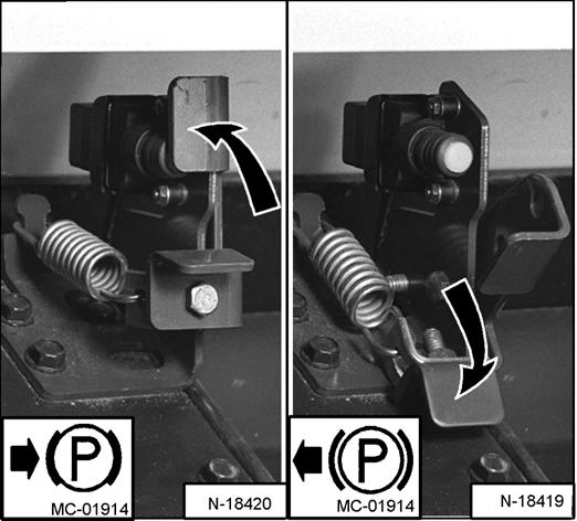
PARKING BRAKE (EARLY MODELS)
Figure OI-13
Push on the top of the pedal [Figure OI-13] to engage the parking brake. The traction drive system will be locked.
Push on the bottom of the pedal [Figure OI-13] to release the parking brake. The traction drive system will be unlocked.*
PARKING BRAKE (LATER MODELS)
Figure OI-14
Press the top of the switch [Figure OI-14] to engage the parking brake. The traction drive system will be locked.
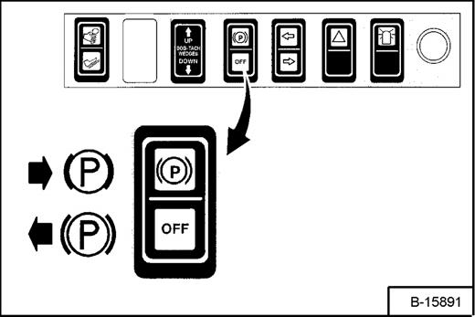
Press the bottom of the switch [Figure OI-14] to disengage the parking brake. The traction drive system will be unlocked.
NOTE: * The TRACTION light on the left instrument panel will remain OFF until the engine is started, the PRESS TO OPERATE LOADER Button is pressed and the parking brake is disengaged.
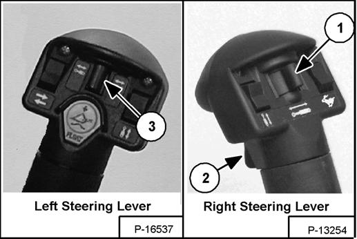
Steering Levers
Figure OI-15
Warning
Avoid Injury Or Death
When operating the machine:
•Keep the seat belt fastened snugly.
•The seat bar must be lowered.
•Keep your feet on the pedal controls or footrests and hands on steering levers.
W-2261-0799
The steering levers control forward and reverse travel and turning the loader [Figure OI-16]
Forward Travel - Push both levers forward.
The steering levers (Item 1) [Figure OI-15] are on the left and right side in front of the seat (loader with hand controls shown).
Move levers smoothly. Avoid sudden starting and stopping.
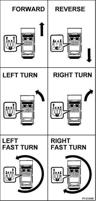
Figure OI-16
Reverse Travel - Pull both levers backward.
Normal Turning - Move one lever farther forward than the other.
Fast Turning - Push one lever forward and pull the other lever backward.
For slow travel speed, push the steering levers forward only a small amount.
To increase travel speed, push both levers farther forward.
For maximum pushing force, push the levers forward only a small amount with the engine at full speed.
Stopping The Bobcat Loader
When the steering levers are moved to the neutral position, the hydrostatic transmission will act as a service brake to stop the loader.
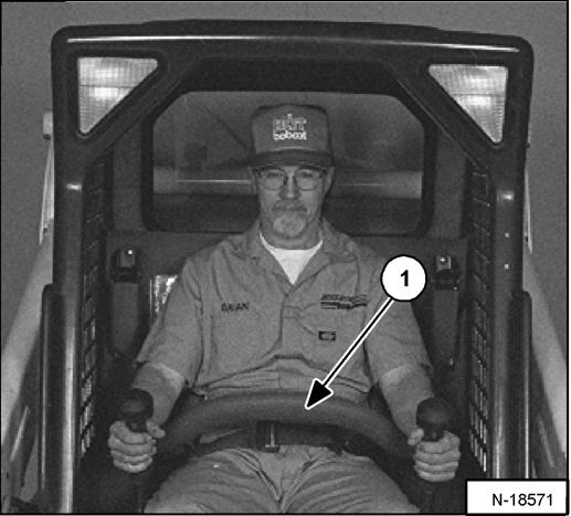
Figure OI-17
Warning
Before you leave the operator’s seat:
•Lower the lift arms, put the attachment flat on the ground.
•Stop the engine.
•Engage the parking brake.
•Raise seat bar
•(Foot Pedal Controls Only) Move pedals until both lock.
•(Advanced Control System (ACS) and Advanced Hand Controls (AHC) Move the hydraulic controls to the NEUTRAL POSITION to make sure that both lift and tilt functions are deactivated. The seat bar system must deactivate the lift and tilt control functions when the seat bar is up. Service the system if hand controls do not deactivate.
W-2398-1003
The seat bar restraint system has a pivoting seat bar with arm rests (Item 1) [Figure OI-17]
The operator controls the use of the seat bar. The seat bar in the down position helps to keep the operator in the seat.
Warning
AVOID INJURY OR DEATH
When operating the machine:
•Keep the seat belt fastened snugly.
•The seat bar must be lowered.
•Keep your feet on the pedal controls or footrests and hands on steering levers.
W-2261-0799
When the seat bar is down, PRESS TO OPERATE LOADER Button is activated, and the brake pedal is released, the lift, tilt, and traction drive functions can be operated. (Traction drive will operate only when the engine is running.)
When, the seat bar is up, the lift, tilt, and traction drive functions are deactivated and both foot pedals (if equipped) will be locked when returned to neutral position.
Hydraulic Controls
Put your feet on the pedals (or footrests) and KEEP THEM THERE any time you operate the loader.
Foot Pedals
Lift Arm Operation [Figure OI-18]
The left pedal controls the lift arms.
Push on the bottom (heel) (Item 2) [Figure OI-18] of the pedal to raise the lift arms.
Push on the top (toe) (Item 3) [Figure OI-18] of the pedal to lower the lift arms.
Lift Arm Float Position [Figure OI-18] Push the top (toe) (Item 3) [Figure OI-18] of the pedal all the way forward until it locks into the float position.
Use the float position of the lift arms to level loose material while driving backward.
Push the bottom of the left pedal to unlock from the float position.
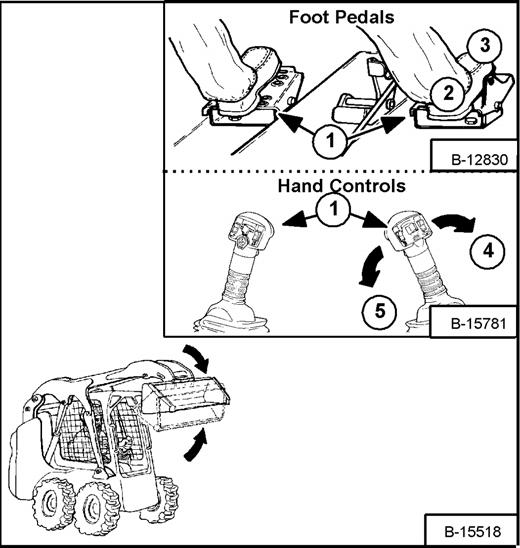
Tilt Operation [Figure OI-19] The right pedal controls the bucket.
Push the bottom (heel) (Item 2) [Figure OI-19] of the pedal to tilt the bucket backward.
Push the top (toe) (Item 3) [Figure OI-19] of the pedal to tilt the bucket forward.
Hand Controls (If Equipped)
Lift Arm Operation [Figure OI-18]
The left hand lever controls the lift arms. Move the left hand lever away from the operator (Item 4) [Figure OI-18] to raise the lift arms.
Move the left hand lever toward the operator (Item 5) [Figure OI-18] to lower the lift arms.
Lift Arm Float Position [Figure OI-18] Move the left hand lever all the way toward the operator (Item 5) [Figure OI18] until it locks into the float position.
Later AHC & ACS Models With Float Button
- To Engage: Press and hold the Float Button (Item 6) [Figure OI-18] while the lever is in neutral. Move the lever to the lift arm down position (Item 5) [Figure OI-18], then release the button.
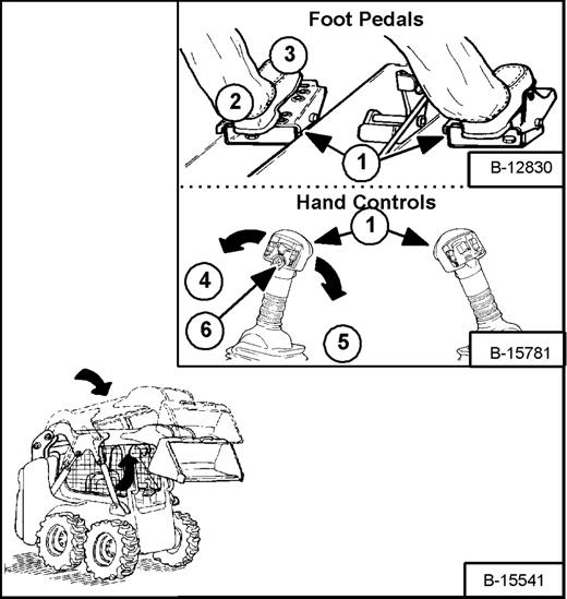
Two foot pedals (or hand controls) (Item 1) [Figure OI18] and [Figure OI-19] control the hydraulic cylinders for the lift and tilt functions.
- To Disengage: Press Float Button again or move the lever to the lift arm up position (Item 4) [Figure OI-18]
Use the float position of the lift arms to level loose material while driving backward.
Move the left hand lever upward to unlock from the float position.
HYDRAULIC CONTROLS (CONT’D)
Hand Controls (If Equipped) (Cont’d)
Tilt Operation [Figure OI-19]
The right hand lever controls the bucket.
Move the right hand lever toward the operator (Item 5) [Figure OI-19] to tilt the bucket backward.
Move the right hand lever away from the operator (Item 4) [Figure OI-19] to tilt the bucket forward.
Warning
Keep both feet on pedals or footrests while operating machine. Failure to do so can cause serious injury.
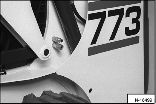
Quick Couplers
To Connect: Remove dirt or debris from the surface of both the male and female couplers, and from the outside diameter of the male coupler. Visually check the couplers for corroding, cracking, damage, or excessive wear. If any of these conditions exist, the coupler(s) must be replaced [Figure OI-20] and [Figure OI-21]
Install the male coupler into the female coupler.
To Disconnect: Hold the male coupler. Retract the sleeve on the female coupler until the couplers disconnect.
Warning
AVOID
Burns
Hydraulic fluid, tubes, fittings and quick couplers can get hot when running machine and attachments. Be careful when connecting and disconnecting quick couplers.
W-2220-0396
HYDRAULIC CONTROLS (CONT’D)
Releasing Hydraulic Pressure (Loader and Attachment)
Loader:
Figure OI-22
•Press the AUXILIARY PRESSURE RELEASE Button (Item 1) [Figure OI-22]. Hold it for two seconds. The engine will stop and release hydraulic pressure.
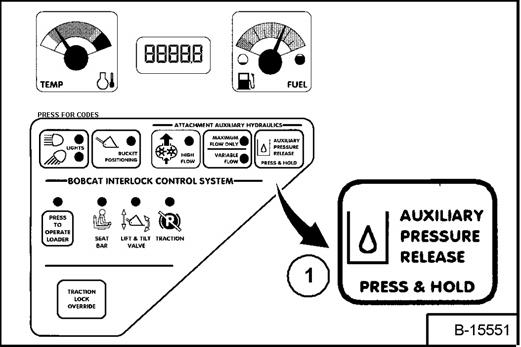
Attachments:
•Follow procedure above to release pressure in loader.
•Connect male coupler from attachment to female coupler of loader then repeat procedure above. This will release pressure in the attachment.
•Connect the female coupler from the attachment.
Hydraulic pressure in the auxiliary hydraulic system can make it difficult to engage quick couplers to an attachment.
Attachment Auxiliary Hydraulic Controls (If Equipped)
Auxiliary Hydraulics Button
Figure OI-23
Figure OI-24
• Variable Flow Variable Flow allows for slow-to-fast movement of auxiliary functions. If you move the auxiliary switch (Items 1) [Figure OI-24] half way, the auxiliary functions move at approximately one-half speed. Press the AUXILIARY HYDRAULICS Button (Item 1) [Figure OI-23] once. The light (Item 2) [Figure OI-23] will be ON.
• Maximum Flow Only Maximum Flow allows for fast movement only. If you move the auxiliary switch (Items 1 or 3) [Figure OI-24], the auxiliary functions move at fast speed; release the switch to stop auxiliary functions. Press the AUXILIARY HYDRAULICS Button (Item 1) [Figure OI-23] a second time. The light (Items 3) [Figure OI-23] will be ON.
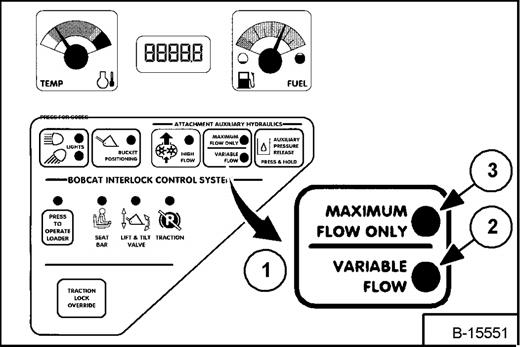
• Disengage Press the AUXILIARY HYDRAULICS Button (Item 1) [Figure OI-23] a third time. Both lights (Items 2 & 3) [Figure OI-23] will be OFF.
NOTE: When the operator is seated and raises the seat bar, the Auxiliary Hydraulic System (Front and Rear) will deactivate.
HYDRAULIC CONTROLS (CONT’D)
FRONT Auxiliary Hydraulics Operation
(RIGHT Steering Lever)
Variable Flow
•Press the AUXILIARY HYDRAULICS Button for Variable Flow (See above).
•Push the switch (Item 1) [Figure OI-24] to the right or left to change the fluid flow direction to the front quick couplers. (EXAMPLE: Open and close grapple teeth.)
Maximum Flow Only
•Press the AUXILIARY HYDRAULICS Button for Maximum Flow. (See Attachment Auxiliary Hydraulic Controls (If Equipped) on Page OI-14.)
Continuous Flow
•After selecting Variable or Maximum Flow, press the front switch (Item 2) [Figure OI-24] to give the front quick couplers a constant flow of fluid with the female coupler being pressurized. (EXAMPLE: Operate a backhoe.) To set reverse flow (male coupler pressurized), hold the auxiliary switch (Item 1) [Figure OI-24] to the left, press Variable or Maximum Flow and then press the front switch (Item 2) [Figure OI-24]. Reverse flow can be used only with augers, power rakes, sweepers, tillers, and vibratory rollers
•To release from continuous operation, press the front switch (Item 2) [Figure OI-24] a second time.
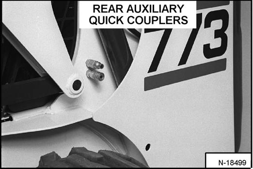
REAR Auxiliary Hydraulics Operation
(LEFT Steering Lever)
•Press the AUXILIARY HYDRAULICS Button for Maximum Flow. (See Attachment Auxiliary Hydraulic Controls (If Equipped) on Page OI-14.)
•Push the switch (Item 3) [Figure OI-24] to the right or left to change the fluid flow direction to the rear quick couplers [Figure OI-25]. (EXAMPLE: Raise and lower rear stabilizers.)
HYDRAULIC CONTROLS (CONT’D)
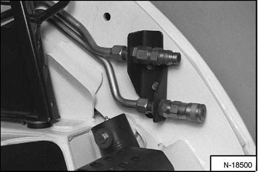
High-Flow Hydraulics Operation (If Equipped)
The High-Flow function provides additional flow to the system to operate an attachment which requires more hydraulic flow (EXAMPLE: Planer).
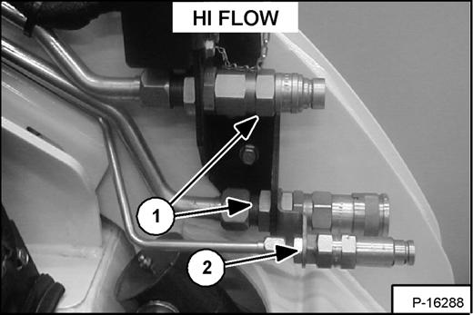
Figure OI-26
•Connect the attachment to the quick couplers (Item 1) [Figure OI-26]
•Some attachments may have a case drain which needs to be the connected to the small quick coupler (Item 2) [Figure OI-26]
•Set the Auxiliary Hydraulics Button for Variable Flow or Maximum Flow Only (See Attachment Auxiliary Hydraulic Controls (If Equipped) on Page OI-14.)
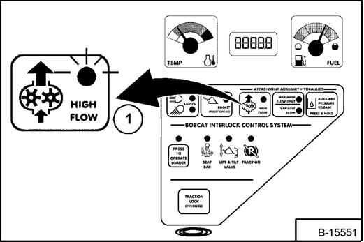
Figure OI-27
•Press the HIGH FLOW Button (Item 1) [Figure OI27]
Secondary Front Auxiliary Hydraulics (If Equipped)
Figure OI-28
If your loader has the HIGH FLOW Option, the secondary front auxiliary quick couplers are included (Item 1) [Figure OI-28]. (Also available separately as a Field Installed Accessory.) These are used when there is a need for additional auxiliary hydraulics (EXAMPLE: Planer side shift).
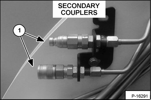
•Connect the attachment to the secondary auxiliary hydraulics (Item 1) [Figure OI-28].
•Set the Auxiliary Hydraulic Button for Variable Flow or Maximum Flow Only. (See Attachment Auxiliary Hydraulic Controls (If Equipped) on Page OI-14.)
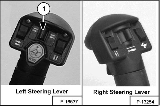
Figure OI-29
•Push switch (Item 1) [Figure OI-29] to the right or left to change fluid flow direction. (EXAMPLE: Side shift on the Planer.)
NOTE: The secondary front auxiliary hydraulics and the rear auxiliary hydraulics operate from the same auxiliary section of the control valve. To operate only one of these auxiliary functions, disconnect the other.
HYDRAULIC CONTROLS (CONT’D)
Secondary Front Auxiliary Hydraulics (If Equipped) (Cont’d)
Important
If high-flow switch is in the ON position, High-Flow Hydraulics will flow through the front auxiliary quick coupler. Damage to unapproved attachments can result. Leave the switch OFF for backhoe operation.
I-2063-1197
Attachment Control Device (ACD) (If Equipped)
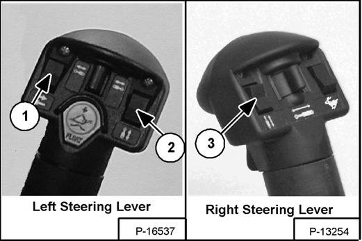
You can then use additional switches (Items 1 thru 3) [Figure OI-32] on the right and left control handles for functions which control some attachments.
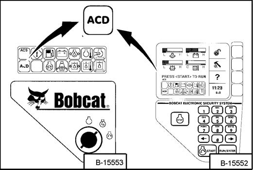
NOTE: When the Dual-Connector Kit is installed, the ACD Icon light [Figure OI-31], in the right instrument panel, will always be ON.
NOTE: When a 7-Pin Attachment, which requires High-Flow, is connected to the loader harness, the Attachment Control Device (ACD) will automatically select High-Flow auxiliary hydraulics.
See the appropriate Attachment Operation & Maintenance Manual for control details.
Warning
Diesel fuel or hydraulic fluid under pressure can penetrate skin or eyes, causing serious injury or death. Fluid leaks under pressure may not be visible. Use a piece of cardboard or wood to find leaks. Do not use your bare hand. Wear safety goggles. If fluid enters skin or eyes, get immediate medical attention from a physician familiar with this injury.
W-2072-0496
When this kit is installed (Item 1) [Figure OI-30], the ACD Icon light [Figure OI-31] on the right instrument panel will be ON when a 7-pin electric controlled attachment is installed.
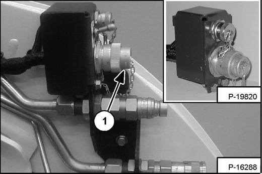
You will need the Dual-Connector (7-pin/14-pin) Kit (Inset) [Figure OI-30] to operate early model attachments. See your Bobcat Loader dealer.
HYDRAULIC CONTROLS (CONT’D)
Bucket Position Valve Operation (If Equipped)
The function of the bucket position valve is to keep the bucket in the same approximate position it is in before you begin raising the lift arms.
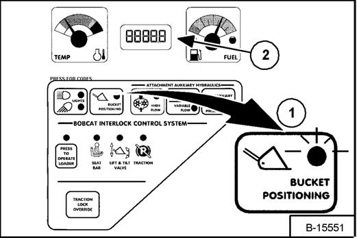
Press BUCKET POSITIONING Button (Item 1) [Figure OI-33] to engage the bucket positioning function. (The light will be ON.) Press again to disengage.
Bucket Positioning functions only during the upward lift cycle.
Shutdown Feature
Press and hold the BUCKET POSITIONING Button (Item 1) [Figure OI-33] for 2 seconds. If the SHUTDOWN feature is installed, Shtdn will appear in the HOURMETER/CODE DISPLAY (Item 2) [Figure OI-33] If it is not installed, BASE will appear. (Operational Code will also appear).
Daily Inspection
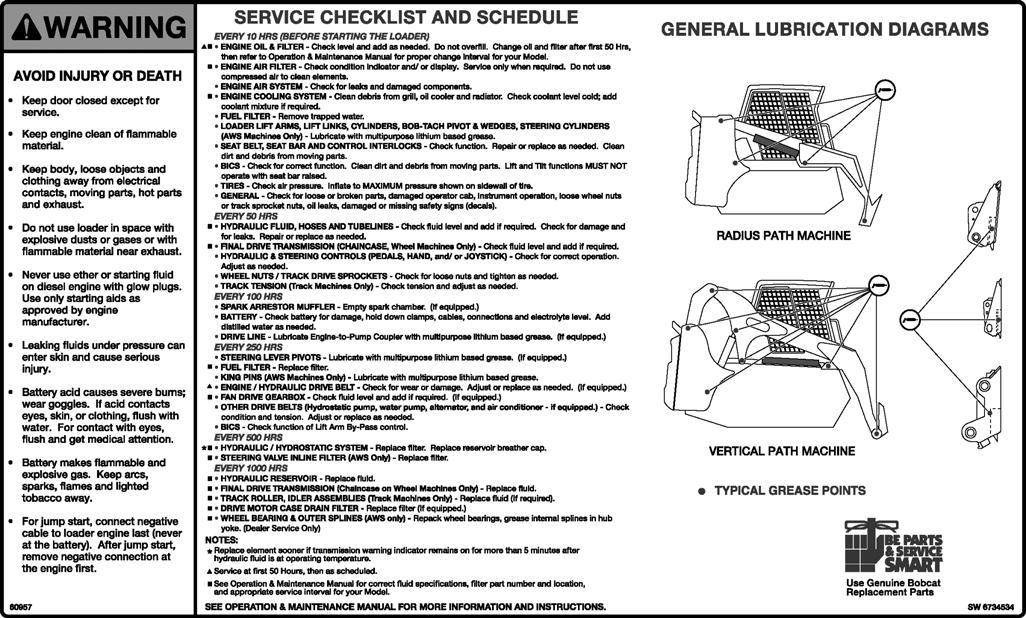
Figure OI-34
Maintenance work must be done at regular intervals. Failure to do so will result in excessive wear and early failures. The Service Schedule [Figure OI-34] is a guide for correct maintenance of the Bobcat Loader. It is located inside the rear door of the loader and also in the MACHINE SIGN TRANSLATION Section.
Daily Inspection and Maintenance
•Engine Oil Level
•Hydraulic/Hydrostatic Fluid Level
•Engine Air Filter, Check Air System for Damage or Leaks
•Engine Coolant Level, Check System for Damage or Leaks
•Operator Cab and Cab Mounting Hardware
•Seat Belt
•Seat Bar and Control Interlocks
•Grease Pivot Pins (Lift Arms, Bob-Tach, Cylinders, Bob-Tach Wedges)
•Tires, Check for Wear, Damage, Correct Air Pressure
•Fuel Filter, Remove Trapped Water
•Loose or Broken Parts, Repair or replace as necessary
•Safety Treads and Safety Signs (Decals), Replace as necessary
•Lift Arm Support Device. Replace if damaged
•Bobcat Interlock Control System (BICS)
Warning
Operator must have instructions before operating the machine. Untrained operators can cause injury or death.
NOTE: Fluids such as engine oil, hydraulic fluid, coolant, etc. must be disposed of in an environmentally safe manner. Some regulations require that certain spills and leaks on the ground must be cleaned in a specific manner. See local, state and federal regulations for correct disposal.