9 minute read
STARTING THE ENGINE (Cont’d)


Do not use ether with glow plug (preheat) systems. Explosion can result which can cause injury or death.
W–2071–1285
Cold Temperature Starting Condition (Optional)
See Normal Starting Condition, Page 16. Turn the key switch to the ON position (readout codes will show first) and the glow plug symbol will be ON [A]
NOTE: If display is showing readout codes the timing of the glow plug activation may be obscured on the display. However, the glow plugs will actually be energized.
The alpha numeric display will indicate the characters GLOXX where XX will show remaining time the glow plugs will be energized. The following chart shows the time glow plugs will be energized dependent on engine coolant temperature.
STARTING THE ENGINE (Cont’d)
Turn the key to the START position and release when the engine starts. If the engine does not start, turn the key switch to the OFF position and ONagain to cycle the flow plugs again. When the engine is running, slowly move the engine speed control forward to increase engine RPM.
If the starting temperature is below 32°F. (0°C.), use the following procedure to make starting easier:
Replace the engine oil with the correct type and viscosity for the anticipated starting temperature (See Oil Specifications Chart Page 41).
Make sure the battery is at full charge.
Install an engine block heater or tank heater.
Stopping The Engine
Pull the engine speed control fully backward to decrease the engine speed. Turn the key switch to the OFF position [A].
Never use attachments or buckets which are not approved by Bobcat Company. Buckets and attachments for safe loads of specified densities are approved for each model. Unapproved attachments can cause injury or death.
The dealer can identify, for each model loader, the attachments and buckets approved by BobcatCompany. The buckets and attachments are approved for Rated Operating Capacity and for secure fastening to the Bob–Tach.
The rated Operating Capacity for this loader is shown on a label in the operator cab (See SPECIFICATIONS Pages 73).
It is determined by using a standard dirt bucket, and material of normal density, such as dirt or dry gravel. If longer buckets are used and load center moves forward and reduces the Rated Operating Capacity. If very dense material is loaded, the volume must be reduced.
Exceeding the Rated Operating Capacity can cause the following problems:
1.Steering the loader may be difficult.
2.Tires may wear faster.
3.There will be a loss of stability.
4.The life of the Bobcat loader will be reduced. Use the correct size bucket for the type and density of material being handled. For safe handling of materials and avoiding machine damage, the attachment (or bucket) should handle a full load without going over the Rated Operating Capacity for the loader. Partial loads make steering more difficult.
NOTE:When a pallet fork is used, different Bob–Tach levers must be installed for clearance at the pallet fork frame. See your dealer for the correct Bob–Tach levers.
Maximum loads to be carried when using a pallet fork are shown in figure [B]
AVOID
INJURY OR DEATH W–2053–0887
ATTACHMENTS AND BUCKETS (Cont’d)
Installing The Bucket Or Attachment
The loader is equipped with the Bob–Tach system. The Bob–Tach is used for fast changing of buckets and attachments. See the Attachment Operation & Maintenance Manual to install other attachments.
Pull the Bob–Tach levers all the way up (Item 1) [A]
Enter the loader.
Fasten the seat belt, lower the seat bar and start the engine.
Release the parking brake.
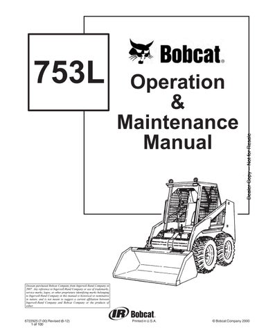
Lower the lift arms and tilt the Bob–Tach forward.
Drive the loader forward until the top edge of the Bob–Tach is completely under the top flange of the bucket [A] (or other attachments).


Be sure the Bob–Tach levers do not hit the bucket.
Tilt the Bob–Tach backward until the cutting edge of the bucket (or other attachment) is slightly off the ground [B]
Stop the engine and exit the loader.
Before you leave the operator’s seat:
* Lower the lift arms, put the attachment flat on the ground.
* Stop the engine.
* Engage the parking brake.
* Raise seat bar.
* (Foot Pedal Controls) Move pedals until both lock.
* (Mechanical Hand Controls) Move the hand controls until both lock. The seat bar system must lock the lift and tilt controls in neutral when the seat bar is up. Service the system if hand controls do not lock correctly.
Bob–Tach levers have spring tension. Hold lever tightly and release slowly. Failure to obey warning can cause injury.
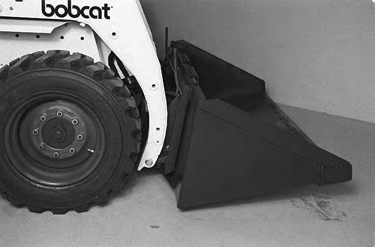
Push down on the Bob–Tach levers until they are fully engaged in the locked position [C]
The levers will contact the frame as shown (Item 1) [C] when locked.
If the levers do not engage in the locked position, see your Bobcat loader dealer for maintenance.
ATTACHMENTS AND BUCKETS (Cont’d)
The wedges (Item 1) [A] must extend through the holes (Item 1) [B] in the mounting frame of the bucket (or attachment), securely fastening the bucket to the Bob–Tach. The wedge is shown extending through the hole in the bucket [A]
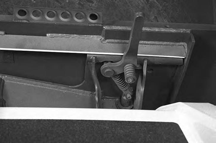
Bob–Tach wedges must extend through the holes in attachment. Lever(s) must be fully down and locked. Failure to secure wedges can allow attachment to come off and cause injury or death.

Removing The Bucket Or Attachment
Put the attachment flat on the ground and lower or close the hydraulic equipment. If the attachment is hydraulically controlled (ie: combination bucket, backhoe, etc.), stop the engine and relieve hydraulic pressure in the auxiliary circuit (See Relieving Hydraulic Pressure, Page 9).
Raise the seat bar, unfasten the seat belt, set theparking brake and exit the loader.
Pull the Bob–Tach levers [C] all the way up.
Disconnect the hydraulic hoses, if necessary. Enter the loader.
Fasten the seat belt, lower the seat bar and start the engine
Release the parking brake.
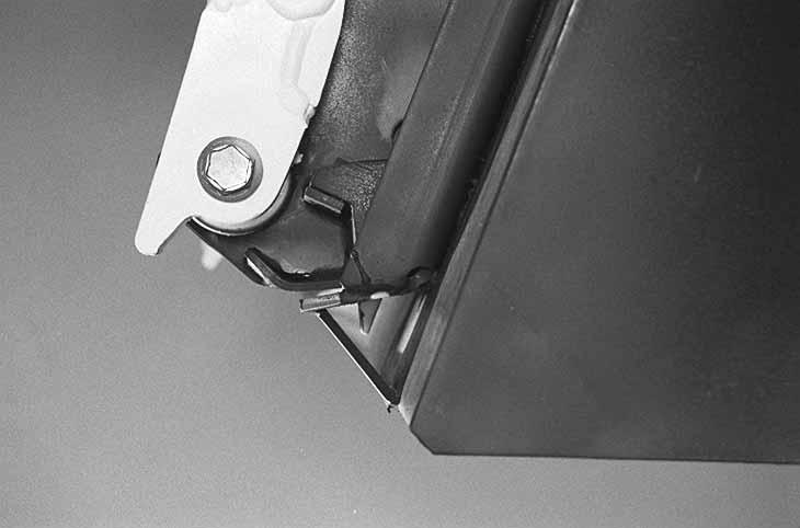
Lower the lift arms and tilt the Bob–Tach forward. Move the loader backward, away from the bucket or attachment [D]
Operating Procedure
Always warm up the engine and hydrostatic system before operating the loader.
Machines warmed up with moderate engine speed and light load have longer life.
I–2015–0284
Operate the loader with the engine at full speed for maximum horsepower. Move the steering levers only a small amount to operate the loader slowly.
New operators must operate the loader in an open area without bystanders. Operate the controls until the loader can be handled at an efficient and safe rate for all conditions of the work area.
With a full bucket, go up to down the slope with theheavy end toward the top of the slope [A] & [B].
With empty bucket, go down or up the slope with the heavy end toward the top of the slope [C] & [D]
Avoid Injury Or Death
• Keep the lift arms as low as possible.
• Do not travel or turn with the lift arms up.
• Turn on level ground.
• Go up and down slopes, not across them.
• Keep the heavy end of the machine uphill.
• Do not overload the machine.
Failure to obey warnings can cause the machine to tip or roll over and cause injury or death.
W–2018–1187
Raise the bucket only high enough to avoid obstructions on rough ground.
OPERATING PROCEDURES (Cont’d)
Filling the Bucket
Push down on the top of the lift pedal until the lift arms are all the way down. Push the top of the tilt pedal to put the cutting edge of the bucket on the ground [A]
Drive slowly forward into the material. Push the bottom of the tilt pedal to raise the front of the bucket [B]
Load, unload and turn on flat level ground. Do not exceed rated operating capacity shown on sign (decal) in cab. Failure to obey warnings can cause the machine to tip or roll over and cause injury or death.
W–2056–1187
Drive backward away from the material.
Emptying the Bucket
Push down on the bottom of the lift pedal to raise the bucket over the truck box or bin [C]
Drive forward slowly until the bucket is over the top of the truck box or bin. Push the top of the tilt pedals until the bucket is empty [C]. If all the material is near the side of the truck or bin, push it to the other side with the bucket.
Never dump over an obstruction, such as a post, that can enter the operator cab. The machine could tip forward and cause injury or death.
W–2057–0694
OPERATING PROCEDURES (Cont’d) Digging Into the Ground
Put the lift arms all the way down. Push the top of the tilt pedal until the cutting edge of the bucket is on theground. Drive forward slowly and continue to tilt the bucket down until it enters the ground [A]
Push the bottom of the tilt pedal a small amount to increase traction and keep an even digging depth. Continue to drive forward until the bucket is full. Whenthe ground is hard, raise and lower the cutting edge of the bucket with the tilt pedal while driving forward slowly.
Push the bottom of the tilt pedal to the tilt the bucket backward as far as it will go when the bucket is full [B]
Leveling the Ground (Using Lift Arms in Float Position)
Push the top (toe) of the lift pedal all the way forwarduntil the pedal is in the locked position (detent) to put the lift arms in a float position [C]
Push the tilt pedal to change the position of the cutting edge on the bucket. With the bucket tilted farther forward, there is more force on the cutting edge and more loose material can be moved.
Never drive forward when the hydraulic control for lift arms is in float position.
Drive backward to level loose material. Push the bottom of the lift pedal to unlock from the detent position.
OPERATING PROCEDURES (Cont’d)
Backfilling
Lower the lift arms and put the cutting edge of the bucket on the ground. Drive forward to the edge of the hole to push the material into the hole [A].
Tilt the bucket forward as soon as it is past the edge of the hole [A]. If necessary, raise the lift arms to empty the bucket.
Parking The Bobcat Loader
Stop the Bobcat loader on level ground.
Lower the lift arms fully and put the edge of the bucket on the ground.
Pull the engine speed control all the way backward. Turn the key switch to the OFF position.
Avoid Injury Or Death
Before you leave the operator’s seat:
• Lower the lift arms, put the attachment flat on the ground.
• Stop the engine.
• Engage the parking brake.
• Raise seat bar, move pedals until both lock.
W–2045–1086
Engage the parking brake.
Lift the seat bar and make sure the foot pedals are in the locked position.
Un–buckle the seat belt. Remove the key from theswitch to prevent operation of the loader by unauthorized personnel.
Adequately designed ramps of sufficient strength are needed to support the weight of the machine when loading onto a transport vehicle. Wood ramps can break and cause personal injury.
A loader with an empty bucket or no attachment must be loaded backward onto the transport vehicle [A]
Be sure the transport and towing vehicles are of adequate size and capacity.
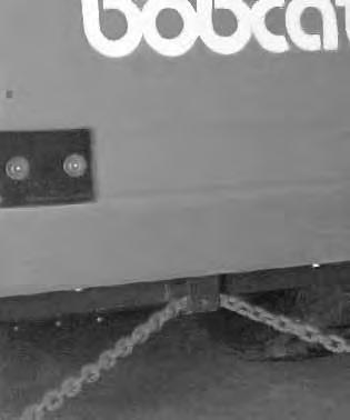
Use the following procedure to fasten the Bobcat loader to the transport vehicle to prevent the loader from moving during sudden stops or when going up ordown slopes [B]
Lower the bucket or attachment to the floor. Stop the engine. Engage the parking brake. Install chains at the front and rear loader tie down positions. Fasten eachend of the chain to the transport vehicle.

Lifting The Loader
Four Point Lift
AVOID INJURY OR DEATH
When operating the machine:
• Keep the seat belt fastened snugly.
• The seat bar must be lowered.
• Keep your feet on the pedal controls.
W–2046–0595
The loader can be lifted with the four point lift which is available as a kit from your Bobcat loader dealer.
Attach cables or chains to lift eyes as shown [A]
Single Point Lift
AVOID INJURY OR DEATH
• Before lifting, check fasteners on single point lift and operator cab.
• Assemble front cab fasteners as shown in this manual.
• Never allow riders in the cab or bystanders within 15 feet (5 meters) while lifting the machine.
W–2007–0497
The loader can also be lifted with the singlepoint lift which is available as a kit from your Bobcat loader dealer.
Attach cables or chains to the single point lift as shown [B]
The single point lift, supplied by Bobcat Company is designed to lift and support the Bobcat loader without affecting roll over and falling object protection features of the operator cab.
Towing The Loader
To prevent damage to the loaders hydrostatic system, the loader must be towed only ashort distance at slow speed (EXAMPLE: Moving the loader onto a transport vehicle.
The towing chain (or cable) must be rated at 1–1/2 times the weight of the loader (See SPECIFICATIONS Page 73).