14 minute read
INSTRUMENT PANEL


(Standard)
The following items are located on the standard instrument panel [A]:
1. LIGHT SWITCH (OPT.) – Controls the work and travel lights.
2. KEY SWITCH – For starting, stopping the engine.
3. FUSE (ACCESSORIES) – To protect the electrical system from overload.
4. FUSE (IGNITION) – To protect the electrical system from overload.
5. HOURMETER – Records the total operating hours of the loader.
6. FUEL GAUGE – Shows the amount of fuel in the fuel tank.
7. ENGINE TEMPERATURE GAUGE – Shows the engine coolant temperature.
8. ENGINE WARNING LIGHT – Lights when engine oil pressure is low or coolant temperature is high. Stop the engine if the light comes ”ON”.
9. TRANSMISSION WARNING LIGHT – Low transmission charge pressure, hydraulic filter needs replacement or high fluid temperature. Stop the engine if the light comes ON.
10. VOLTMETER – Shows the condition of the battery and the rate of charge.
11. PREHEAT BUTTON – For preheating the glow plugs before starting the engine.
12. OPTIONAL AUXILIARY HYDRAULICS MODE SWITCH – For engaging the auxiliary hydraulics (front & rear).
INSTRUMENT PANEL (Optional BOSS®)
The following items are located on the (optional) instrument panel [A] & [B]:
1. KEY SWITCH – Controls the starting and stopping of the engine. If engine doesn’t start turn the key to the OFF position for 3 seconds to reset the fueltimer module.
2. LIGHT SWITCH (OPTIONAL) – Controls the work and travel lights.
3. DIAGNOSTIC COUPLER – Connector for diagnostic tool to make service checks of the system operation unit and other components.
4. DISPLAY PANEL – The display has the following symbols and functions (Ref. 6 thru 19).
5. OPTIONAL HYDRAULICS MODE SWITCH – For engaging the auxiliary hydraulics (front and rear).
6. FUEL – Shows the amount of fuel in the tank.
7. BATTERY VOLTAGE – Shows the condition of the battery and charge rate. Also will indicate a WARNING for high and low voltage.
8. ENGINE OIL SYMBOL – Shows engine oil pressure. Flashing symbol indicated low oil pressure. (Warning & Shutdown)
9. ENGINE COOLANT SYMBOL – Shows engine coolant temperature and/or low coolant level (SHUTDOWN & Warning).
10. FUEL FILTER – If fuel pump and bar flashes it is a low fuel WARNING H2O symbol indicates water in the fuel filter (NOT FUNCTIONAL AT THIS TIME).
11. SHUTDOWN SYMBOL – The symbol is associated with any shutdown condition. When this symbol comes ON the shutdown will occur in 30 seconds. During shutdown the buzzer will sound continuously and the symbol will flash until the key is turned OFF.
NOTE: The engine can be restarted for 30–second periods to move the loader after a shutdown condition.
12. WARNING SYMBOL – The symbol will be ON when any warning or shutdown is activated. The warning symbol is also used to indicatea warning if there is no related symbol on the display. During a warning the buzzer will beep three times andsymbol will be ON continuously.
13. HOURMETER – Records the total operating hours of the loader. The five character code will display the operating hours to the nearest tenth. When SHUTDOWNS or WARNINGS occur an alpha–numeric code will be displayed in the hourmeter area to inform the operator of the problem (See SYSTEM ANALYSIS Page 61 for code listing). During a SHUTDOWN or WARNING the hourmeter symbol is not visible.
14. CHARGE PRESSURE AND FILTER CONDITION – Flashing symbol indicates low fluid charge pressure and SHUTDOWN. If arrows are ON with gear/drop it is fluid charge pressure.This symbol will also indicate a clogged hydraulic fluid filter.
15. AIR FILTER CONDITION – This symbol will indicate a clogged air filter element.
16. GLOW PLUG – The symbol will flashwhen the glow plugs are energized. The hourmeter will also contain characters GLOXX where XX indicates the remaining time the glow plugs will be ‘‘ON’’. Glow plug will count down in 5 second increments.
17. ENGINE SPEED – This symbol will indicate an engine overspeed WARNING and SHUTDOWN.
18. PARKING BRAKE – This symbol will indicate when the brake is engaged (NOT FUNCTIONAL AT THIS TIME.
19. HYDRAULIC FLUID TEMPERATURE – This symbol will indicate a high fluid temperature and SHUTDOWN or WARNING.
Engine Speed Control
The engine speed control (Item 1) [A] is at the right side of the operator’s seat. Engine speed is controlled by moving the control forward to increase the enginespeed and backward to decrease the engine speed.

Parking Brake
Lock the parking brake by pushing down on the top (toe) of the pedal [B]
Avoid Injury Or Death
When operating the machine:
• Keep the seat belt fastened snugly.
• The seat bar must be lowered.
• Keep your feet on the pedal controls.
W–2046–0595
The steering levers (Item 1) [A] are on the right and left side in front of the seat.

For safe control of the loader always move the levers slowly and smoothly. Only a small movement is necessary to move the loader.
The steering levers control forward and reverse travel of the loader [B]
FORWARD TRAVEL – Push both levers forward.
REVERSE TRAVEL – Pull both levers backward.
NORMAL TURNING – Move one lever farther forward than the other.
FAST TURNING – Push one lever forward and pull the other lever backward.
For slow travel speed, push the steering levers forward only a small amount.
To increase travel speed, push both levers farther forward.
For maximum pushing force, push the levers forward only a small amount with the engine at full RPM.
Reverse
RIGHT TURN 753L Bobcat Loader Operation & Maintenance Manual –6–
Left Turn
Hydraulic Controls
Foot Pedals
Keep both feet on pedals while operating machine. Failure to do so can cause serious injury.
W–2002–1285
Put your feet on the pedals and KEEP THEM THERE any time you operate the loader.
Two foot pedals (Item 1) control the hydraulic cylinders for the lift and tilt function [A].
Lift Arm Operation
The left pedal controls the lift arms. Push on the bottom (heel) (Item 2) [A] of the pedal to raise the lift arms.
Push on the top (toe) (Item 3) [A] of the lift pedal all the way forward until it locks into detent (float).
Use the float position of the lift arms to level loose material while driving backward.
Tilt Operation
The right pedal controls the action of the bucket. Push the top (toe) (Item 4)[A] of the pedal to tiltthe bucket forward.
Push the bottom of the pedal (heel) (Item 5)[A] to tilt the bucket backward.
Bucket Position Valve Operation
The function of the bucket positioning valve isto keep the bucket in the same approximate position it is placed in, prior to the upward lift cycle.
Bucket positioning functions automatically during the upward lift cycle only.
HYDRAULIC CONTROLS (Cont’d)
Auxiliary Hydraulics Operation (Standard)
Described below is the operation of the optional auxiliary hydtraulics used with the standard instrument panel.
NOTE: Both steering lever controls are blank (no switches) as standard.
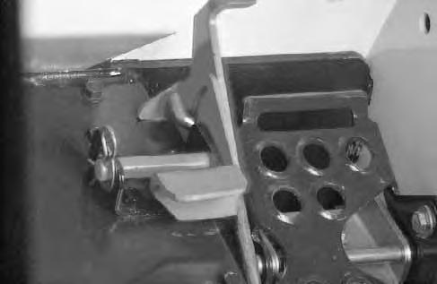
Press the mode switch (Item 1) [A] (on the instrument panel) to allow for the front and optional rear auxiliary hydraulics, the light (Item 2) [A] will come ON.
The switch (Item 1)[B] on the rightsteering lever controls the front auxiliary hydraulics and the switch (Item 2) [B] on the left steering lever controls the rear auxiliary hydraulics.
Switch (Item 4) [B] controls the optional horn.
FRONT AUXILIARY CONTROL (OPTIONAL):
Push switch (Item 1) [B] in the right or left direction (with mode switch engaged & top light ON) to change fluid flow direction to the front quick couplers [C] (Example: Open and close grapple teeth).

REAR AUXILIARY CONTROL (OPTIONAL):
Push the switch (Item 2) [B] in the right or left direction (with mode switch engaged & top light ON) to changethe fluid flow direction to the rear quick couplers [C] (Example: Raise or lower rear stabilizers).
DETENT CONTROL:
Push the mode switch (Item 1) [A] the second time to engage the detent function and both lights (Item 2 & 3) [A] will come ON. Push the front button (Item 3) [B] to give the front auxiliary hydraulics a constant flow of fluid(Example: Operate a backhoe).
To release the detent position, push the button (Item 3) [B] again.
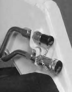
RELIEVE PRESSURE AT FRONT QUICK COUPLERS:
Turn the key switch to the aux. pressure relief position (all the way to the left and hold the key in this position until the engine stops) to release the hydraulicpressure at the front quick couplers.
RELIEVE PRESSURE AT REAR QUICK COUPLERS:
With the engine running, press the mode switch (Item 1) [A] to engage the auxiliary hydraulics, the light (Item 2) [A] will come ON.
Push the heel of the tilt pedal so the hydraulic fluid goes over the main relief pressure and at the same time push switch (Item 2) [B] back and forth several times to relieve the pressure at the rear quick couplers. Release the tilt pedal. Stop the engine.

CFRONT AUXILIARY QUICK COUPLERS (OPTIONAL)
REAR AUXILIARY QUICK COUPLERS (OPTIONAL)


HYDRAULIC CONTROLS (Cont’d)
Auxiliary Hydraulics Operation (Optional BOSS)
Described below is the operation of the optional auxiliary hydraulics used with the optional BOSS instrument panel.
NOTE: The right and left steering lever controls are blank (no switches) as standard.
Press the mode switch (Item 1) [A] (on the instrument panel) to allow for the front and optional rear auxiliary hydraulics, the light (Item 2) [A] will come ON.
The switch (Item 1) [B] on the right steering lever controls the front auxiliary hydraulics and the switch (Item 2) [B] on the left steering lever controls the rear auxiliary hydraulics.

Switch (Item 4) [B] controls the optional horn.
FRONT AUXILIARY CONTROL (OPTIONAL):
Push switch (Item 1) [B] in the right or left direction (with mode switch engaged & top lightON) to change fluid flow direction to the front quick couplers [C] (Example: Open and close grapple teeth).
REAR AUXILIARY CONTROL (OPTIONAL):
Push the switch (Item 2) [B] in the right or left direction (with mode switch engaged & top light ON) to change the fluid flow direction to the rear quick couplers [C] (Example: Raise or lower rear stabilizers).
DETENT CONTROL:
Push the mode switch (Item 1) [A] the second time to engage the detent function and both lights (Items 2 & 3) [A] will come ON. Push the front button (Item 3)[A] to give the front auxiliary hydraulics a constant flow of fluid [B] (Example: Operate a backhoe).
To release the detent position, push the button (Item 3) [B] again.
RELIEVE PRESSURE AT FRONT QUICK COUPLERS:
Turn the key switch to the aux. pressure relief position (all the way to the left and hold the key in this position untilthe engine stops) to release the hydraulic pressure at the front quick couplers.
RELIEVE PRESSURE AT REAR QUICK COUPLERS:
With the engine running, press the mode switch (Item 1) [A] to engage the auxiliary hydraulics, the light (Item 2) [A] will come ON.
Push the heel of the tilt pedal so the hydraulic fluid goes over the main relief pressure and at the same time push switch (Item 2) [B] back and forth several times to relieve the pressure at the rear quick couplers. Release the tilt pedal. Stop the engine.
CFRONT AUXILIARY QUICK COUPLERS (OPTIONAL)
REAR AUXILIARY QUICK COUPLERS (OPTIONAL)
Daily Inspection
The loader must be in good operating condition [A] Check the following items:
• Engine Oil
• Hydraulic/Hydrostatic Fluid
• Engine Cooling System
• Operator Cab, Seat Belt, Seat Bar & Pedal Interlocks
• Lift Arm & Cylinder Pivot Pins
• Tires & Tire Pressure
• Any Loose or Broken Parts
• Safety Tread & Safety Signs
• Check the instrument panel display readout for faulty codes (Page 61).
NOTE:Fluids such as engine oil, hydraulic fluid, coolant, etc. must be disposed of in an environmentally safe manner. Some regulations require that certain spills and leaks on the ground must be cleaned in a specific manner. See local, state and federal regulations for correct disposal.
AInstructions are necessary before operating or servicing machine. Read Operation & Maintenance Manual, Handbook and signs (decals) on machine. Follow warnings and instructions in the manuals when making repairs, adjustments or servicing. Check for correct function after adjustments, repairs or service. Failure to follow instructions can cause injury or death.
W–2003–0797
6578218
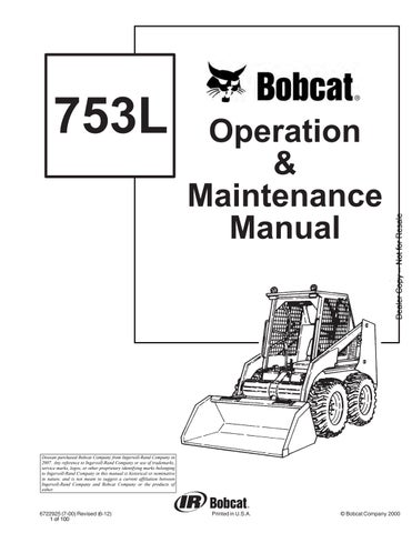
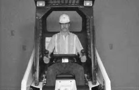
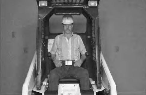
Seat Bar Restraint System
The seat bar restraint system has a pivoting seat bar (Item 1) [A] with arm rests and has spring loaded interlocks for the lift and tilt control pedals. The operator controls the use of the seat bar. The seat bar in the down position helps to keep the operator in the seat. The interlocks require the operator to lower the seat bar in order to operate the foot pedal controls. When the seat bar is up, the lift and tilt control pedals are locked when returned to the NEUTRAL POSITION.
AVOID INJURY OR DEATH
When operating the machine:
• Keep the seat belt fastened snugly.
• The seat bar must be lowered.
• Keep your feet on the pedal controls.
W–2046–0595
The spring loaded interlocks (Item 1) [B] control the locking and unlocking functions of the control pedals.
The interlocks (Item 1) [B] require the operator to lower the seat bar (Item 2) [B] which allows the operator to move the foot pedals to control the lift and tilt functions.
When the seat bar is lowered, it pushes the interlock (Item 1) [B] down on both sides, releasing the pedal linkages (Item 3) [B] from the interlocks.
The pedals will pivot in both directions when the interlock is down.
AVOID INJURY OR DEATH
Before you leave the operator’s seat:
• Lower the lift arms, put the attachment flat on the ground.
• Stop the engine.
• Engage the parking brake.
• Raise seat bar, move pedals until both lock.
W–2045–1086
AVOID INJURY OR DEATH
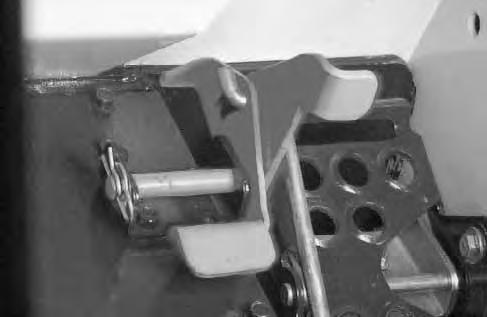
The seat bar system must lock the lift and tilt control pedals in neutral when the seat bar is up. Service the system if pedals do not lock correctly.
W–2105–1285
When the seat bar is raised, spring forces raise the interlocks [C].
The foot pedals will not pivot when the interlock is up.
Refer to the Seat Bar Restraint System Inspection & Maintenance (Page 35).
Getting Ready For Operation
Read the Operation & Maintenance Manual and the Operator’s Handbook before operating the loader [A]
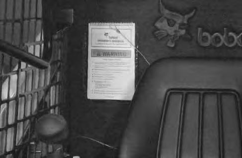
Operator must have instructions before running the machine. Untrained operators can cause injury or death.
W–2001–0596
Use the bucket or attachment steps, grab handles and safety treads (on top of the loader lift arm crossmember and main frame) to get on and off the loader [B]
Safety treads are installed on the Bobcatloader to provide a slip resistant surface for getting on and off the loader. Keep safety treads clean and replace when damaged. Replacement treads are available from your dealer.
Pull the seat lever (Item 1) and adjust the seat position for comfortable operation of the loader controls [C].

Fasten the seat belt snugly and adjust it so that the buckle is centered between the hips [D].
Avoid Injury Or Death
When operating the machine:
• Keep the seat belt fastened snugly.
• The seat bar must be lowered.
• Keep your feet on the pedal controls.
W–2046–0595
GETTING READY FOR OPERATION (Cont’d)
Lower the seat bar [A]
Be sure the parking brake is engaged.
All controls must be in the neutral position before you start the engine (See Starting The Engine, Page 13).
Keep feet on the pedals while seated in the loader [B]


Starting The Engine
When an engine is running in an enclosed area, fresh air must be added to avoid concentration of exhaust fumes. If the engine is stationary, vent the exhaust outside. Exhaust fumes contain odorless, invisible gases which can kill without warning.
W–2050–1285
AVOID INJURY OR DEATH
• Engines can have hot parts and hot exhaust gas. Keep flammable material away.
• Do not use machines in atmosphere containing explosive gas.
W–2051–1086
STARTING THE ENGINE (Cont’d)
Normal Starting Condition (Standard)
Adjust the seat position for comfortable operation of the foot pedals and steering levers.
Fasten the seat belt snugly and adjust it so the buckle is centered between the hips.
Lower the seat bar [A]
Put the foot pedals and steering levers in neutral (center) position (Item 1) [B]
Set the engine speed control to half speed position (Item 2) [B]
Turn the key to the ON position. The engine and transmission warning light will be ON when the key is on the the engine is stopped (Item 3) [B]
Turn the key to start position (Item 4) and release it when the engine starts [B]
Do not engage the starter for longer than 15 seconds at a time. Longer use can damage the starter by overheating. Cool the starter for one minute between uses.
I–2034–0284
When the engine starts, release the key and it will return to the run position (Item 5) [B]
STOP THE ENGINE IF THE WARNING LIGHTS DO NOT GO OFF.
Without turning the key to the START position, turn the key to the RUN position (Item 5)[B] for starting the loader in cold weather (See Cold Temperature Starting Condition, Page 15).
NOTE: Upon failed start, if the key is turned OFF, wait for at least three seconds before turning the key ON to reset the fuel timer module.
Do not use ether with glow plug (preheat) systems. Explosion can result which can cause injury or death.
W–2071–1285
Cold Temperature Starting Condition (Standard)
See Normal Starting Condition, Page 14. Turn the key switch to the RUN position.
Push the PREHEAT button (Item 1) [A] on the left side of the instrument panel to preheat the glow plugs.
Refer to the decal on the left side of the operator cab for operation of the preheat system [B].
Follow the steps under Normal Starting Condition and repeat the Preheating procedure until the engine starts.
If the temperature is below 32°F (0°C), use the following procedure to make starting the engine easier:
Replace the engine oil with the correct type and viscosity for the anticipated starting temperature (See Oil Specifications, Page 41).
Make sure the battery is at full charge.
Install block or tank heater on the engine.
Warming The Hydraulic/Hydrostatic System
When the temperature is below –20°F (–30°C), hydrostatic oil must be warmed before starting. The hydrostatic system will not get enough oil at low temperatures and will be damaged. Park the machine in an area where the temperature will be above 0°F (–18°C) if possible.
I–2007–1285
Let the engine run for a minimum of 5 minutes to warm the engine and hydrostatic fluid before operating the loader. If the warning light comes ON when operating the loader (cold), more warm up time is needed.
STARTING THE ENGINE (Cont’d)
Normal Starting Condition (Optional)
Adjust the seat position for comfortable operation of the foot pedals and steering levers.
Fasten the seat belt snugly and adjust it so the buckle is centered between the hips.
Lower the seat bar [A]
Put the foot pedals and steering levers in neutral(center) position (Item 1) [B].
Be sure the parking brake is engaged.
Set the engine speed control to the 1/2 speed position (Item 2) [B].
Turn the key to ON position, one beep will sound and the display symbols will be ON [C]. Turn the key to START (See Cold Temperature Starting Condition). Release the key when the engine starts.
Do not engage the starter for longer than 15 seconds at a time. Longer use can damage the starter by overheating. Cool the starter for one minute between uses.
When the key is turned ON, watch the alpha numeric display for readout codes. These readouts codes are from the previous work shift when a WARNING may have occured (See SYSTEM ANALYSIS, SERVICE CODES Page 61).
The readout codes may be viewed again by turning the key switch OFF and then ON again without starting the engine.
Once the engine is started, the microprocessor will clear all readout codes from memory. The codes will not reappear in subsequent key ON conditions unless the problem recurs.
NOTE: Upon failed start, if the key is turned OFF, wait for at least three seconds before turning the key ON to reset the fuel timer module.