17 minute read
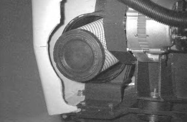
AIR CLEANER SERVICE

from Bobcat 653 Foot Pedal & Hand Control Loader Operation & Maintenance Manual 6900444 - PDF DOWNLOAD

Condition Indicator
Replace the large (outer) filter element only when the red ring shows in the window of the condition indicator (Item 1) [A].
NOTE:Before replacing the filter element, push the button on the condition indicator (Item 2) [A]. Start the engine. If the red ring does not show, do not replace the filter element.
Replacing Filter Element
Outer Element:
Release the two dust cover fasteners (Item 1) [B].

Remove the dust cover and latch the fasteners.
Remove the large filter element (Item 1) [C].
NOTE:Make sure all sealing surfaces are free of dirt and debris.
Install the new filter element.
Install dust cover.
Check the air intake hose for damage. Check the air cleaner housing for damage. Check to make sure all connections are tight.
Inner Element:
Only replace the inner filter element under the following conditions:
• Replace the inner filter element every third time the outer filter is replaced.
• Press the button to remove the red ring in the condition indicator after the outer element has been replaced. Start the engine and run at full RPM. If the red ring shows again, replace the inner filter element.
Remove the inner filter wing nut.
Remove the inner filter.
Install a new filter and tighten the wing nut.
Fuel System
Fuel Specifications
Use only clean, high quality diesel fuel, Grade No. 2 or Grade No. 1.
The following is one suggested blending guideline which should prevent fuel gelling problems:
2No.1
Contact your fuel supplier for local recommendations.
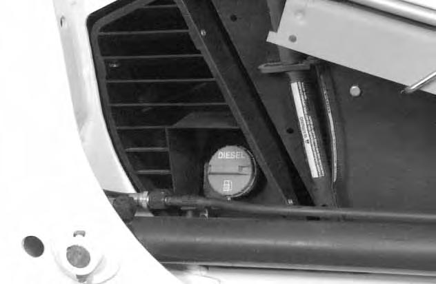
Filling the Fuel Tank
Stop and cool the engine before adding fuel. NO SMOKING! Failure to obey warnings can cause an explosion or fire.
Remove the fuel fill cap (Item 1) [A]
Use a clean, approved safety container to add fuel of the correct specifications. Add fuel only in an area that has free movement of air and no open flames or sparks. NO SMOKING! [B]
Install and tighten the fuel fill cap [A]
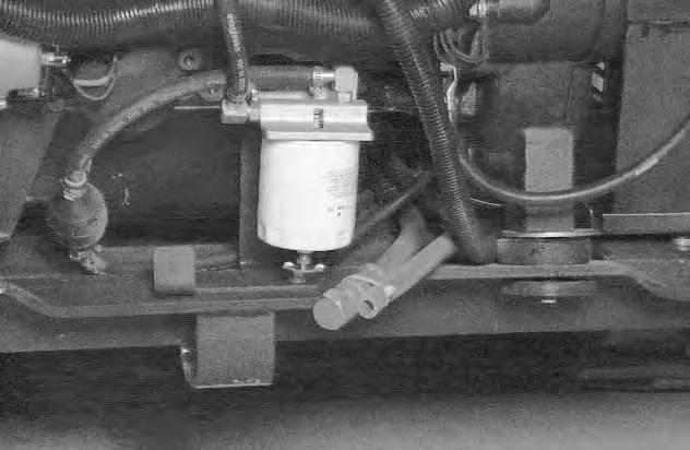
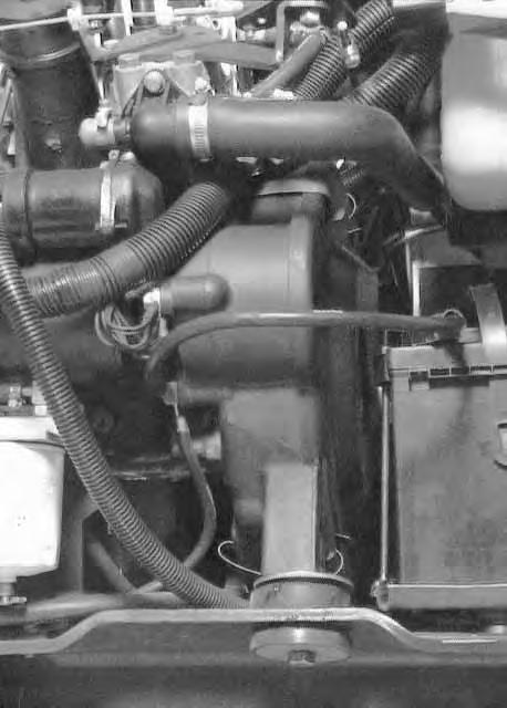
Fuel Filter
Always clean up spilled fuel or oil. Keep heat, flames, sparks or lighted tobacco away from fuel and oil. Failure to use care around combustibles can cause explosion or fire which can result in injury or death.
See the SERVICE SCHEDULE Page 37 for the service interval when to remove the water from the fuel filter.
Loosen the drain (Item 1) [C] at the bottom of the filter element to drain any water from the filter.
See the SERVICE SCHEDULE Page 37 for the service interval when to replace the fuel filter.
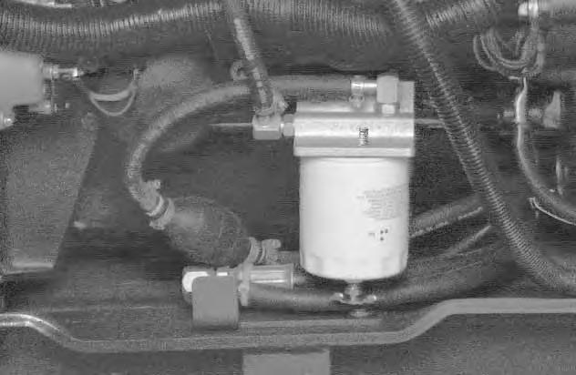
To replace the fuel filter element, use a filter wrench to remove the filter element (Item 2) [C].
Clean the area around the filter housing. Put oil on the seal of the new filter element. Install the fuel filter, and hand tighten. Remove the air from the fuel system. (See Page 52.)
FUEL SYSTEM (Cont’d)
Removing Air From the Fuel System
After replacing the fuel filter element or when the fueltank has run out of fuel, the air must be removed from the fuel system before starting the engine.
Diesel fuel or hydraulic fluid under pressure can penetrate skin or eyes, causing serious injury or death. Fluid leaks under pressure may not be visible. Use a piece of cardboard or wood to find leaks. Do not use your bare hand. Wear safety goggles. If fluid enters skin or eyes, get immediate medical attention from a physician familiar with this injury.
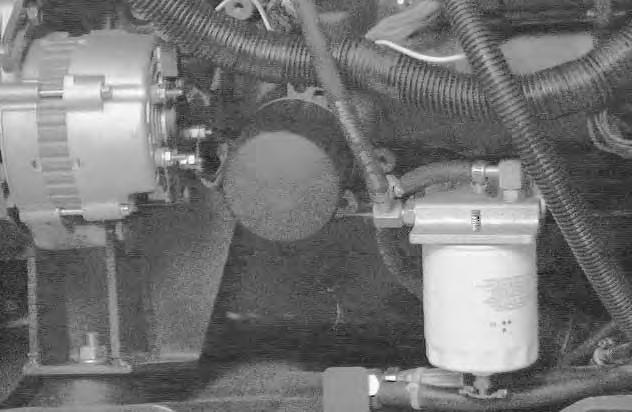
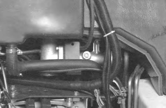
Open the vent (Item 1) [A] on the fuel filter housing.
Operate the hand pump (priming bulb) (Item 2) [A] until fuel flows from the vent with no air bubbles.
Close the vent (Item 1) [A] on the fuel filter housing.
Open the vent (Item 1) [B] on the fuel injection pump.
Operate the hand pump (priming bulb) (Item 2) [A] until the pump feels solid.
Tighten the vent plug.
Start the engine. It may be necessary to open the vent plug (at the fuel injection pump) briefly until the engine runs smoothly.

Engine Lubrication System
Checking Engine Oil
Check the engine oil level every day.
Open the rear door and remove the dipstick (Item 1) [A]
Keep the oil level between the marks on the dipstick. Use a good quality motor oil that meets API Service Classification of CD or better. (See Oil Chart below.)
Install the dipstick and close the rear door.
Oil Chart
RECOMMENDED SAE VISCOSITY NUMBER (LUBRICATION OILS FOR ENGINE CRANKCASE)
TEMPERATURE RANGE ANTICIPATED BEFORE NEXT OIL CHANGE
Replacing Oil And Filter
See the SERVICE SCHEDULE Page 37 for the service interval for replacing the engine oil and filter.
Run the engine until it is at operating temperature. Stop the engine.

Open the rear door.
Remove the drain plug (Item 1) [B]. Drain the oil into a container.
ENGINE LUBRICATION SYSTEM (Cont’d)
Replacing Oil And Filter (Cont’d)
Remove the oil filter (Item 1) [A].
Clean the filter housing surface. Put clean oil on the new oil filter gasket. Install the filter and hand tighten.
Install and tighten the drain plug.
Remove the filler cap (Item 1) [B] from the oil fill tube. Put 6 qts. (5,7 L) of oil in the engine. (SeeOil Chart Page 53.) [B]

Start the engine and let it run for several minutes. Stop the engine. Check for leaks at the oil filter and check the oil level.
The oil level should be between the top and bottom marks on the dipstick [C].

If the level has reached the bottom mark, add oil until it reaches the top mark.
Install the dipstick and the oil fill cap.
Close the rear door before operating the loader.
Always clean up spilled fuel or oil. Keep heat, flames, sparks or lighted tobacco away from fuel and oil. Failure to use care around combustibles can cause explosion or fire which can result in injury or death.
W–2103–1285
Engine Cooling System
Check the cooling system every day to prevent over–heating, loss of performance or engine damage.
Wear safety glasses to prevent eye injury when any of the following conditions exist:
• When fluids are under pressure.
• Flying debris or loose material is present.
• Engine is running.
• Tools are being used.
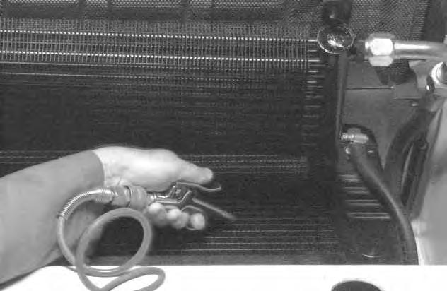
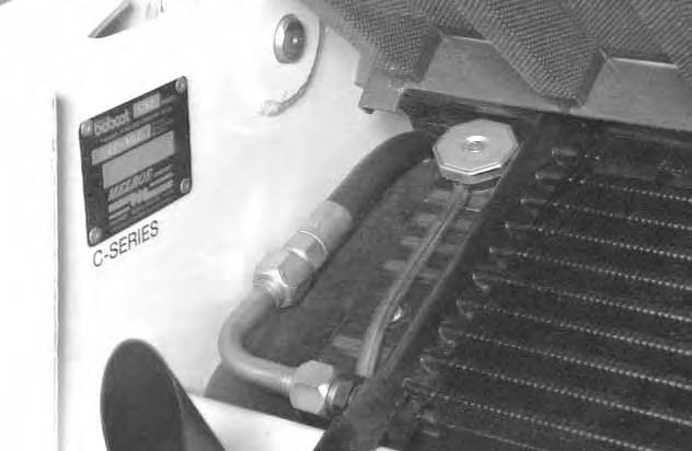
Cleaning The Cooling System
Open the rear door and raise the rear grill.
W–2019–1285
Use air pressure or water pressure to clean the top of the oil cooler [A].

Raise the oil cooler and clean the top of the radiator [B] Check cooling system for leaks.
Checking The Coolant Level
Open the rear door. Check the coolant level in the coolant recovery tank (Item 1) [C] on the right side of the engine.
The coolant recovery tank must be 1/3 full.
Lower the rear grill and close the rear door before operating the loader.
ENGINE COOLING SYSTEM (Cont’d) Replacing The Coolant
Do not remove radiator cap when the engine is hot. You can be seriously burned.
W–2070–1285
Install jackstands under the rear corners of the loader.
Raise the operator cab. (See Raising the Operator Cab Page 38.)
Open the rear door and raise the rear grill.
Remove the radiator cap (Item 1) [A]
Open the drain valve (Item 1) [B].
The drain valve is located on the engine block behind the hydrostatic pumps.
Drain the coolant into a container from the drain hose (Item 1) [C]
After all the coolant is removed, close the drain valve. Mix the coolant in a separate container. (See SPECIFICATIONS for correct capacity, Page 85.)
NOTE:The loader is factory filled with propylene glycol coolant. DO NOT mix propylene glycol with ethylene glycol.
Propylene Glycol
Add premixed coolant, 47% water and 53% propylene glycol to the recovery tank if the coolant level is low.
One gallon and one pint of propylene glycol mixed with one gallon of water is the correct mixture of coolant to provide a –34°F (–37°C) freeze protection.
Use a refractometer to check the condition of propylene glycol in your cooling system.
Fill the radiator with the premixed coolant. Install the radiator cap.
Fill the coolant recovery tank 1/3 full.
Run the engine until it is at operating temperature. Stop the engine. Check the coolant level in the recovery tank when cool. Add coolant to the recovery tank as needed.
Lower the operator cab. (SeeLowering The Operator Cab Page 39.)
Remove the jackstands.
Lower the rear grill and close the rear door before operating the loader.
Alternator Belt
Adjusting The Alternator Belt
Stop the engine.
Raise the operator cab. (See Raising the Operator Cab Page 38.)
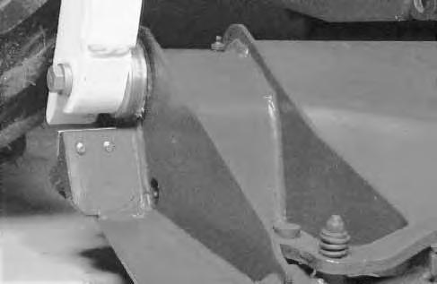
Loosen the alternator mounting bolt (Item 1) [A]
Loosen the adjustment bolt (Item 2) [A]
Move the alternator until the belt has 5/16 inch (8,0 mm) movement at the middle of the belt span with 15 lbs. (66 N) of force.

Tighten the adjustment bolt and mounting bolt.
Lower the operator cab. (SeeLowering The Operator Cab Page 39.)
TIMING BELT (Engine)
The engine timing belt MUST be replaced every 1,600 hours.
Never install a used timing belt on an engine after it has been removed for other service or repair.
Never attempt to clean a dirty or oily timing belt; replace it. Find and correct the source of contamination.
Serious engine damage can result from a broken timing belt.
DRIVE BELT Adjusting The Drive Belt
No special tools are needed to adjust the drive belt. See the SERVICE SCHEDULE Page 37 for the service interval.

Stop the engine. Open the rear door.
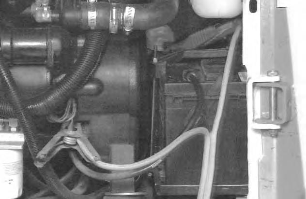
Disconnect the negative (–) battery cable(Item 1) [A].The battery may be removed for additional working clearance. (See Page 63.)
Remove the three belt shield fasteners (Item 2) [A]
Remove the belt shield (Item 1) [B]
DRIVE BELT (Cont’d)
Adjusting The Drive Belt (Cont’d)
There is a decal[A] on the loader which shows the correct drive belt adjustment.
The drive belt tension is maintained by a spring loaded idler pulley. The range of adjustment is indicated by a pointer.
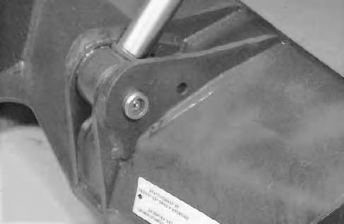
Loosen the idler mounting bolt (Item 1) [B]
The pointer will be at the 7 o’clock position (Item 2) [B] when the idler is not under spring tension. (Belt isloose.)
Turn the adjustment nut (Item 3) [B] to tighten the drive belt.
Tighten the belt until the pointer is at the 9 o’clock position (Item 1) [C]. The idler is against the stop at this position.
NOTE:Never leave the idler adjusted against the stop. Always loosen adjustment slightly.
Loosen the adjustment nut slightly so that the idler is under spring tension.
Tighten the idler mounting bolt (Item 2) [C] to 25–28 ft.–lbs. (34–36 Nm).
Run the engine for a few minutes.
Stop the engine and recheck the pointer position.
Readjust if necessary.
Close the rear door before operating the loader.
DRIVE BELT Drive Belt Replacement
Stop the engine. Open the rear door.
Remove the negative (–) cable (Item 1) [A] from the battery.
The battery may be removed for additional working clearance. (See Removing And Installing The Battery Page 63.)
Remove the belt shield fasteners (Item 2) [A].
Remove the belt shield. (See Page 58.)
Loosen the lock nut (Item 1) [B] and the adjusting nut (Item 2) [B]
Remove the drive belt from the pump pulley and flywheel. Remove the drive belt from the loader [C].
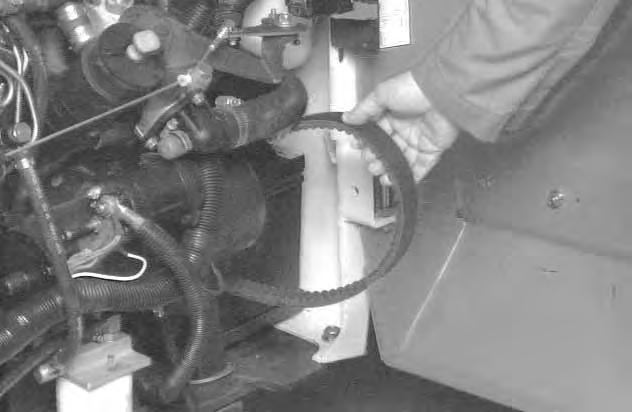

Install the new drive belt.
Re–install the fan drive belt.
Adjust the drive belt. (See Page 50.)
Connect the negative (–) cable to the battery.
Install the belt shield.
Close the rear door before operating the loader.
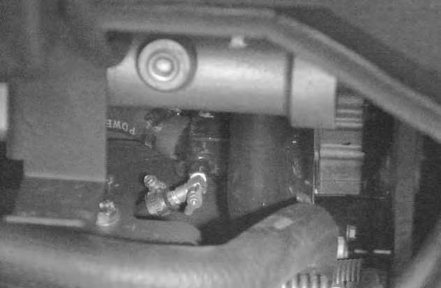
ELECTRICAL SYSTEM Description
The loader has a 12 volt, negative ground alternator charging system. The electrical system is protected by fuses located in the engine compartment. The fuses will protect the electrical system when there is an electrical overload. The reason for the overload must be found before starting the engine again.

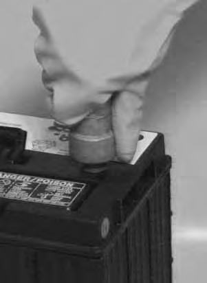
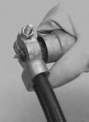
Cleaning Battery Terminals
The battery cables must be clean and tight. Check the water level in the battery. Remove any acid or corrosion from the battery and cables with a sodium bicarbonate and water solution [A].
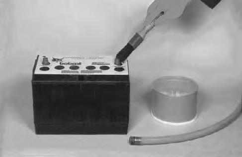
Put grease on the battery terminals and cable ends to prevent corrosion.
Batteries contain acid which burns eyes and skin on contact. Wear goggles, protective clothing and rubber gloves to keep acid off body.
In case of acid contact, wash immediately with water. In case of eye contact get prompt medical attention and wash eye with clean, cool water for at least 15 minutes.
If electrolyte is taken internally drink large quantities of water or milk! DO NOT induce vomiting. Get prompt medical attention.
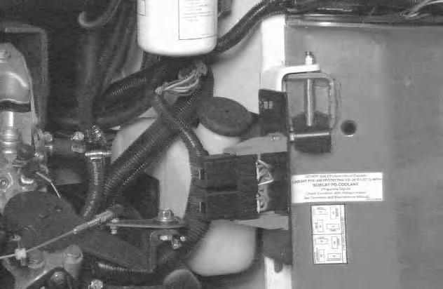
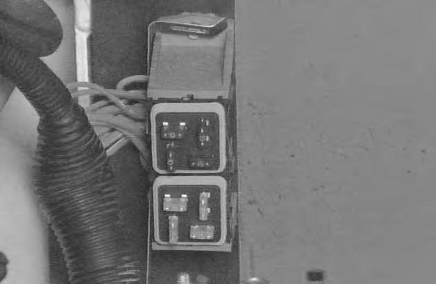
Fuse Location
The electrical system for loaders is protected by eight fuses (Item 1) [B] located in the fuse block (Item 1) [C]. Remove the fuse block cover to access the fuses. Fuses protect the electrical system from an overload. The fuse block (Item 1) [C] is located in the engine compartment mounted on the upper rear door hinge bracket.
The decal inside the rear door specifies the fuse sizes used in loader circuits [D]
ELECTRICAL SYSTEM (Cont’d) Using A Booster Battery (Jump Starting)
If it is necessary to use a booster battery to start the engine, BE CAREFUL! There must be one person in the operator’s seat and one person to connect and disconnect the battery cables.
The ignition must be in the OFF position. The booster battery to be used must be 12 volt.
Batteries contain acid which burns eyes and skin on contact. Wear goggles, protective clothing and rubber gloves to keep acid off body.
In case of acid contact, wash immediately with water. In case of eye contact get prompt medical attention and wash eye with clean, cool water for at least 15 minutes.
If electrolyte is taken internally drink large quantities of water or milk! DO NOT induce vomiting. Get prompt medical attention.
W–2065–1296
Keep arcs, sparks, flames and lighted tobacco away from batteries. When jumping from booster battery make final connection (negative) at engine frame.
Do not jump start or charge a frozen or damaged battery. Warm battery to 60°F. (16°C.) before connecting to a charger. Unplug charger before connecting or disconnecting cables to battery. Never lean over battery while boosting, testing or charging.
Battery gas can explode and cause serious injury.
W–2066–1296
Connect the end of the first cable (Item 1) [A] to the positive (+) terminal of the booster battery. Connect the other end of the same cable (Item 1) [B] to the positive terminal on the loader battery.
Connect the end of the second cable (Item 2) [A] to the negative (–) terminal of the booster battery. Connect the other end of the same cable (Item 2) [B] to the engine ground cable.
Keep cables away from moving parts. Start the engine. After the engine has started, remove the ground (–) cable (Item 2) [B] first. Remove the cable from the positive terminal on the loader battery.
Damage to the alternator can occur if:
• Engine is operated with battery cables disconnected.
• Battery cables are connected when using a fast charger or when welding on the loader (Remove both cables from the battery).
• Extra battery cables (booster cables) are connected wrong.
I–2023–1285
ELECTRICAL SYSTEM (Cont’d)
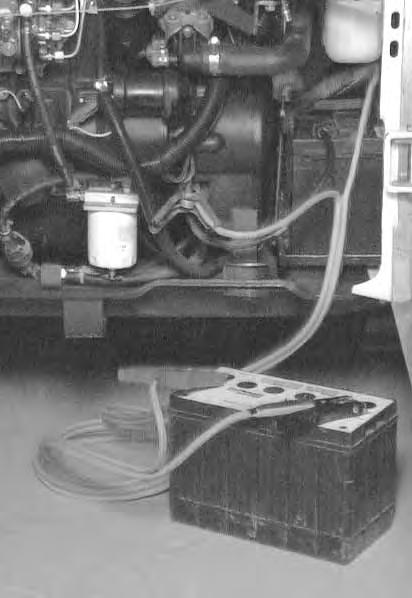
Removing And Installing The Battery
Open the rear door.
Disconnect the negative (–) battery cable (Item 1) [A].
Remove the battery fastener (Item 2) [A]
Disconnect the positive (+) battery cable (Item 1) [B].
Remove the battery from the loader.
Always clean the terminals and cable ends when installing a new battery [C]
When installing the battery in the loader, do not touch any metal parts with the battery terminals.

Connect and tighten the battery cables. Connect the negative (–) cable last to prevent sparks.
Close the rear door before operating the loader.

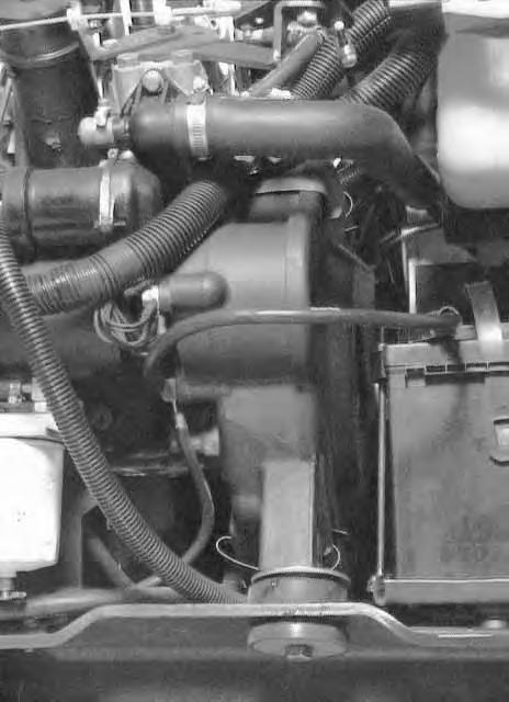
Fan Gearbox
See the SERVICE SCHEDULE Page 37 for the correct service interval.
Checking and Maintaining
Raise the operator cab. (See Raising The Operator Cab Page 38.)
Remove the plug (Item 1) [A] to check the lubricant level.
If the level is low, add SAE 90W gear lube through the check plug hole until the lubricant flows from the hole. Install and tighten the plug.
Lower the operator cab. (SeeLowering The Operator Cab Page 39.)
FINAL DRIVE TRANSMISSION (CHAINCASE)
Checking And Adding Oil
The chaincase contains the final drive sprockets and chains and uses the same type of oil as the hydraulic/hydrostatic system. (See SPECIFICATIONS Page 85.)
Drive the loader on a level surface. Stop the engine. Remove the plug (Item 1) [B] from the front of the chaincase housing.

If oil can be reached with the tipof the your finger through the hole, the oil level is correct.
If the level is low, add oil through the check plug hole until the oil flows from the hole. Install and tighten the plug.
Removing Oil From The Chaincase
Remove the cover (Item 1) [C] which is installed over the drain plug at the rear of the chaincase.
Remove the drain plug (Item 1) [D] and drain the oil into a container.
Check the drain plug and replace as necessary. Install the cover and tighten the bolts.
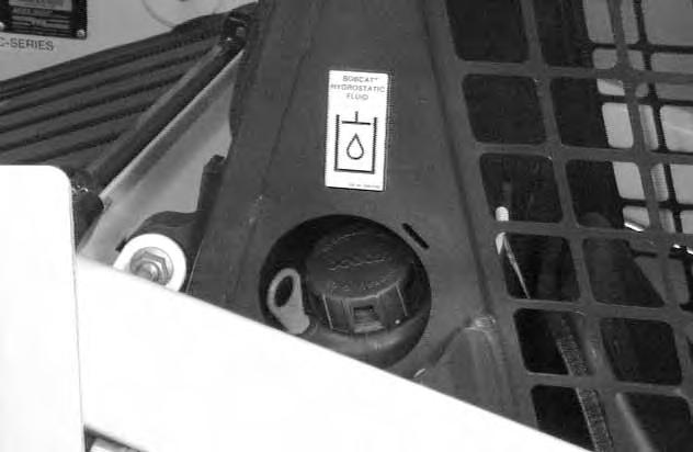
HYDRAULIC/HYDROSTATIC SYSTEM Checking And Adding Fluid
Use only recommended fluid in the hydraulic system. (See SPECIFICATIONS Page 85.)
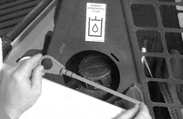

Stop the loader on a level surface. Lower the lift arms and tilt the Bob–Tach fully back.
Stop the engine.
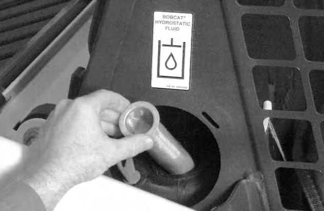
Remove the dipstick (Item 1) [A]
The fluid level must be between the marks on the dipstick [B].
If fluid is needed, remove the fill cap (Item 2) [A]
Clean the hydraulic reservoir fill screen [C].
Add the fluid as needed to bring the level to the top mark on the dipstick [B]
Install the dipstick.
Install the fill cap.
Replacing Hydraulic/Hydrostatic Filter
See the SERVICE SCHEDULE Page 37 for the correct service interval.
Open the rear door.
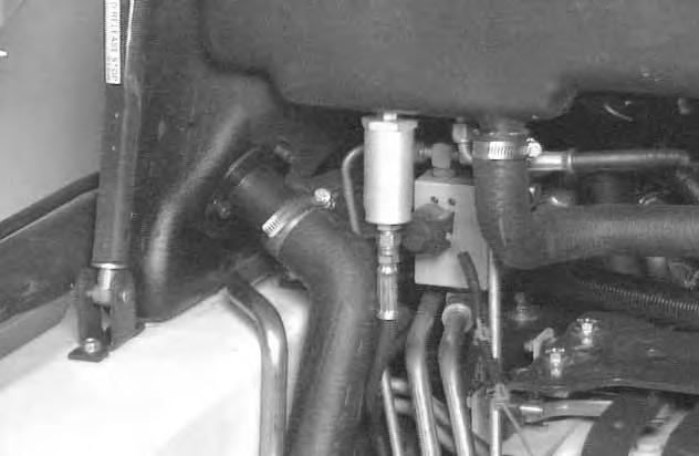
Remove the filter element (Item 1) [D]
Clean the surface of the filter housing where theelement seal contacts the housing. Put clean oil onthe rubber seal of the filter element.
Install and hand tighten the filter element.
Close the rear door before operating the loader.
HYDRAULIC/HYDROSTATIC SYSTEM (Cont’d) Replacing Hydraulic Fluid
See the SERVICE SCHEDULE Page 37 for the service interval.
The fluid must also be replaced if it becomes contaminated or after major repairs.
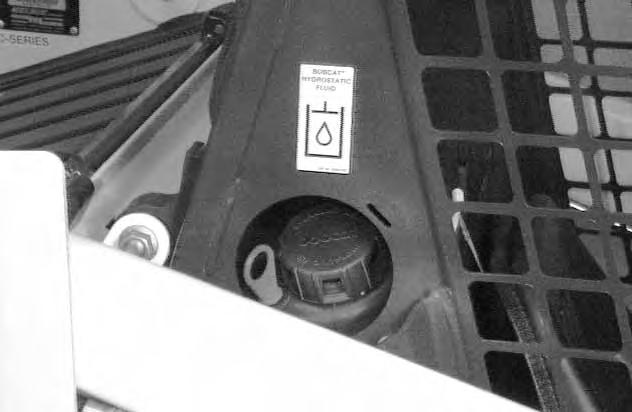
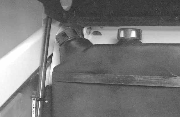
Remove the reservoir fill cap (Item 1) [A]
NOTE:Be sure the rubber gasket is installed on the fill cap [A].
Raise the operator cab. (See Raising The Operator Cab Page 38.)
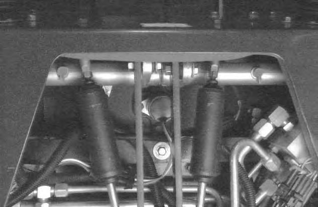
Disconnect the hose from the case drain filter (Item 1)[B] located on the reservoir, plug the filter and case drain hose.
Disconnect the hoses from the case drain filter (Item 1) [C] located on the left drive motor, plug the filter and case drain hose.
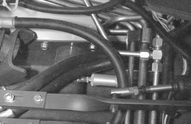
Remove the case drain filters (Item 1)[B] & [C] and drain the fluid into a container.
Replace the hydraulic/hydrostatic filter element.
Replace both hydrostatic motor case drain filters (Item 1) [B] & [C]
When all the fluid is removed from the reservoir, reconnect the hose to case drain filter on the reservoir.
Add the correct fluid to the reservoir until the fluid level is between the marks on the dipstick. DO NOT fill above the top mark on the dipstick.
Hydraulic fluid escaping under pressure can have sufficient force to enter a person’s body by penetrating the skin and cause serious injury and possibly death if proper medical treatment by a physician familiar with this injury is not received immediately.
W–2145–0290
Always clean up spilled fuel or oil. Keep heat, flames, sparks or lighted tobacco away from fuel and oil. Failure to use care around combustibles can cause explosion or fire which can result in injury or death.
W–2103–1285
Start the engine and operate the loader hydraulic controls. Stop the engine. Check for leaks. Check thefluid level in the reservoir and add as needed.
Lower the operator cab. (SeeLowering The Operator Cab Page 39.)
HYDRAULIC/HYDROSTATIC SYSTEM (Cont’d)
Hydraulic Reservoir Breather Cap
See SERVICE SCHEDULE Page 37 for the correct service interval.
Remove the breather cap (Item 1) [A]
NOTE:Be sure the rubber gasket (Item 1) [B] is installed on the fill cap.

Clean the filter (Item 2) [B] from the breather cap.
Make sure the baffle washer (Item 3) [B] is installed in the hydraulic reservoir.

Replace the breather cap at regular intervals. See SERVICE SCHEDULE Page 37.
Spark Arrestor Muffler
See the SERVICE SCHEDULE Page 37 for service interval for cleaning the spark arrestor muffler.

Do not operate the loader with a defective exhaust system.
This loader is factory equipped with a U.S.D.A. Forestry Service approved spark arrestor muffler. It is necessary to do maintenance on this spark arrestor muffler to keep it in working condition. The spark arrestor muffler must be serviced by dumping the spark chamber every 100 hours of operation.
If this machine is operated on flammable forest, brush or grass covered land, it must be equipped with a spark arrestor attached to the exhaust system and maintained in working order. Failure to do so will be in violation of California State Law, Section 4442 PRC.
Make reference to local laws and regulations for spark arrestor requirements.
I–2022–0595
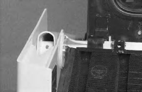
Stop the engine. Open the rear door and rear grill. Remove the plug (Item 1) [A] from the bottom of the muffler.
When an engine is running in an enclosed area, fresh air must be added to avoid concentration of exhaust fumes. If the engine is stationary, vent the exhaust outside. Exhaust fumes contain odorless, invisible gases which can kill without warning.
W–2050–1285
Stop engine and allow the muffler to cool before cleaning the spark chamber. Wear safety glasses or goggles. Failure to obey can cause serious injury.
W–2011–1285
Never use machine in atmosphere with explosive dust or gases or where exhaust can contact flammable material. Failure to obey warnings can cause injury or death.
W–2068–1285
When the engine is running during service, the steering levers must be in neutral and the parking brake engaged. Failure to do so can cause injury or death.
W–2006–0284
Start the engine and run for about 10 seconds while a second person, wearing safety glasses, holds a piece of wood over the outlet of the muffler.
This will force contaminants out through the cleanout hole.
Stop the engine. Install and tighten the plug.
Lower the rear grill and close the rear door before operating the loader.
Lubrication Of The Bobcat Loader
Lubricate the loader as specified in the SERVICE SCHEDULE Page 37 for the best performance of the loader.
Record the operating hours each time you lubricate the Bobcat loader.

Always use a good quality lithium based multi–purpose grease when you lubricate the loader. Apply the lubricant until extra grease shows.

Lubricate the following locations on the loader:
LUBRICATION OF THE BOBCAT LOADER (Cont’d)
BOBCAT INTERLOCK CONTROL SYSTEM (BICS™ ) Troubleshooting Chart
BOBCAT INTERLOCK CONTROL SYSTEM (BICS™)
Troubleshooting Chart
The following list shows the effects which can happen to the loader, and the probable causes when the BICS Controller lights are off or flashing. Have service procedures performed ONLY BY QUALIFIED BOBCAT SERVICE PERSONNEL.
Flashing Indicator Means System Problem
Effect on Operation of Loader IndicatorWhen Light Is Number of LightLight ON Light OFF OFFFlashes
(See Your Bobcat Dealer for Service)
Cause
SeatOperator in SeatNo Operator in SeatLift and tilt functions2seat sensor circuit shorted to battery will not operate. voltage*.
3Seat sensor circuit shorted to ground.
Seat BarSeat Bar DownSeat Bar UpLift, tilt and traction2Seat bar sensor circuit shorted to functions will not battery voltage*. operate.
3Seat bar sensor circuit shorted to ground.
ValveControl Valve CanControl ValveLift and tilt functions1Valve output circuit is open. Be UsedCannot Be Usedwill not operate.2Valve output circuit shorted to battery voltage*.
3Valve output circuit shorted to ground.
3Valve output circuit is not grounded.
TractionLoader can beLoader cannot beLoader cannot be1Traction lock hold coil circuit is open. moved forward &moved forward andmoved forward and2Traction lock hold coil circuit shorted backward.backward. backward. to battery voltage*.
3Traction lock hold coil circuit shorted to ground.
4Traction lock pull coil circuit is open.
5Traction lock pull coil circuit is shorted to battery voltage*.
6Traction lock pull coil circuit is shorted to ground.
PowerBICS ControllerBICS Controller isLift, tilt and traction is operatingnot operatingfunctions will not correctly.correctly. operate.
NOTES:
(1)If the seat and/or seat bar sensor circuits are open, the corresponding lights will be OFF. If one of the lights stay OFF, check the circuit for continuity. See Inspection & Maintenance Instructions in Preventive Maintenance section.
(2)If all five lights flash repeatedly, the voltage supply is greater than 16 volts or less than 9 volts.
(3)Flashing patterns will repeat every 3.25 seconds.
(4)If seat indicator light does not go ON, check for debris, dirt or objects under or behind the seat.
NOTE: If the Seat Bar is lowered before the seat sensor is activated, a 10 second delay will occur before the valve and traction lights come on. (only loaders with BICS controller S/N’s above 200,000 will have this delay.)
* Normal BICS operating voltage is less than the electrical system voltage. If voltage is more, the circuit is shorted to system voltage.