28 minute read
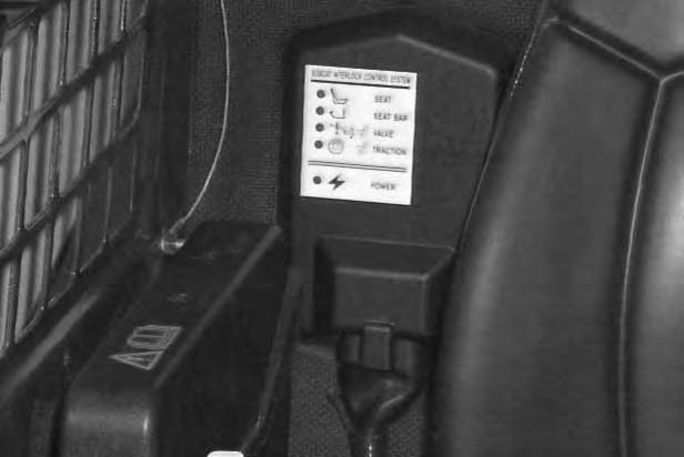
BOBCAT INTERLOCK CONTROL SYSTEM (BICS


Inspecting The BICS™ Controller (Engine STOPPED – Key ON)
1.Sit in the operator’s seat. Turn key ON, lower the seat bar and disengage the parking brake. All five BICS Controller lights should be ON (Items 1, 2, 3, 4 & 5) [A].
2.Engage the parking brake and raise the seat bar fully. Seat bar light (Item 2) [A], valve light (Item 3) [A] and traction light (Item 4) [A] should be OFF.
3.Raise up slightly off the seat. Seat light (Item 1) [A] should be OFF.
NOTE:Record what lights are blinking (if any) and number of blinks. Refer to Page 60.
4.Exit the loader and press traction lock override button. Traction light (Item 4) [A] should be ON. Press override button again and traction light (Item 4) [A] should be OFF.
Inspecting The Seat And Seat Bar Sensors (Engine RUNNING)
5.Sit in the operator’s seat. Lower the seat bar. Engage the parking brake. Fasten the seat belt.
6.Start the engine and operate at low idle. While raising the lift arms, raise the seat bar fully. The lift arms should stop. Repeat using the tilt function.
Inspecting The Traction Lock (Engine RUNNING)
7.Fasten the seat belt, disengage the parking brake, and raise the seat bar fully. Move the steering levers slowly forward and backward. The traction lock should be engaged. Lower the seat bar.
8.Engage the parking brake pedal and move the steering levers slowly forward and backward. The traction lock should be engaged.
Inspecting The Lift Arm By–Pass Control
9.Raise the lift arms six feet (2 m) off the ground. Stop the engine. Pull and hold the by–pass control knob. Push the top (toe) of the left (lift) pedal. the lift arms will slowly lower.
Maintenance
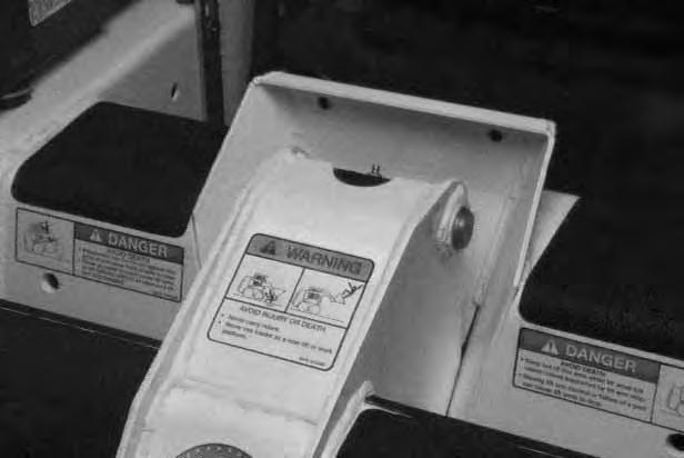
Clean any debris, dirt or objects from under or behind the operator seat [B] & [C]. The rear of the seat must move up and down.
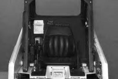
Inspect both Seat Rail Covers [C] for wear or damage. Replace if necessary.
Clearance is necessary under the seat spring (Item 1)[C] and the seat, to allow the seat to move upand down freely. With adequate clearance, the seat sensor will be allowed to function correctly.
Inspect seat bar pivot area for tightness of linkage bolts. Replace parts that are damaged. Use only genuine Bobcat replacement parts.
The Bobcat Interlock Control System (BICS) must deactivate the lift, tilt and traction drive functions. If it does not, contact your dealer for service. DO NOT modify the system.
Avoid Injury
Never service or adjust the machine when the engine is running unless instructed to do so in the manual.
W–2012–0290
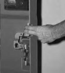
Keep the rear door closed when operating the machine. Failure to do so could seriously injure a bystander.

Put your fingers into the slot in the rear door and pull on the latch handle [A]
Pull the rear door open.
Push the door stop up into the top hinge before closing the rear door [A]
Close the rear door before operating the loader.
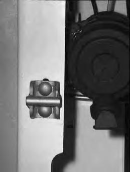
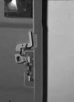
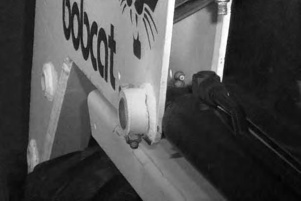
Adjusting The Latch
The door latch catch (Item 1) [B] can be adjusted side to side and up/down for alignment with the door latch mechanism.
The door latch mechanism (Item 2) [B] can be adjusted backward or forward for alignment with the door catch.
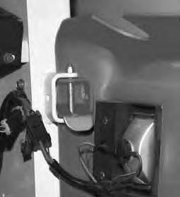
Close the rear door before operating the loader.
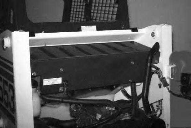
Rear Grill
To remove the rear grill, remove the four grill mounting bolts (Item 1) [C].
Lift the rear grill up and remove from the loader.
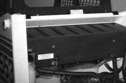
Air Cleaner Service
See the SERVICE SCHEDULE Page 29 for the interval to service the air cleaner system.
Check the air intake hose for damage. Check the air cleaner housing for damage. Check to make sure all connections are tight.
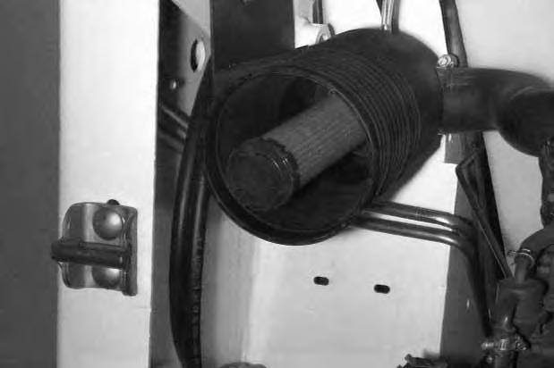
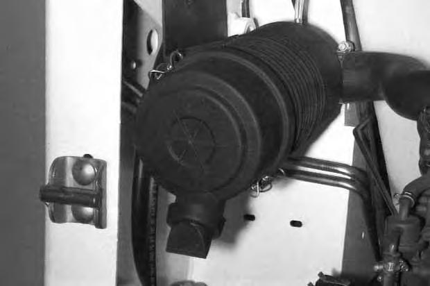
Replace the large (outer) filter element only when the red ring shows in the window (Item 1) [A] of the condition indicator.
NOTE:Push the button on the condition indicator (See Inset) and start the engine. If the red ring does not show, do not replace the filter element [A].
Disengage the clamps (Item 1) and remove the dust cover (Item 2) [B].
Outer Element:
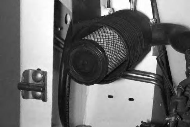
Pull the outer filter element from the air cleaner housing [C]
NOTE:Make sure all sealing surfaces are free of dirt and debris.
Install a new outer element.
Install the dust cover and fasten the clamps.
Inner Element:
Only replace the inner filter element under the following conditions:
• Replace the inner filter element every third time the outer filter is replaced.
• Replace the inner filter element when the red ring still shows in the condition indicator window after the outer filter is replaced.
Pull the inner filter element from the air cleaner housing [D]
NOTE:Make sure all sealing surfaces are free of dirt and debris.
Install the new inner element.
Record the operating hours of the loader on the decal inside the rear door.
Fuel System
Fuel Specifications
Use only clean, high quality diesel fuel, Grade No. 2 or Grade No. 1.
The following is one suggested blending guideline which should prevent fuel gelling problems:
Temp. F°/C° No. 2No. 1
+15o(–9o) 100% 0%
Down to –20o/–29o 50% 50% Below –20o/–29o 0% 100%
We recommend an operator contact their fuel supplier for local recommendations.
Filling The Fuel Tank
Stop and cool the engine before adding fuel. NO SMOKING! Failure to obey warnings can cause an explosion or fire.
Remove the fuel fill cap [A].
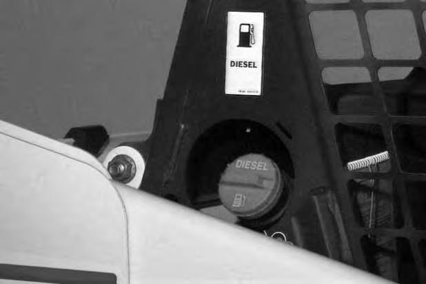
Use a clean, approved safety container to add fuel of the correct specifications. Add fuel only in an area that has free movement of air and no open flames or sparks. NO SMOKING !
Install and tighten the fuel fill cap [A]
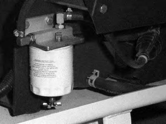
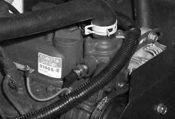
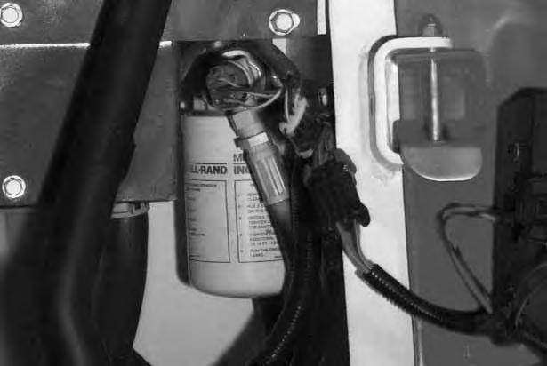
Fuel Filter
See the SERVICE SCHEDULE Page 29 for the service interval when to remove the water from the fuel filter and to replace the fuel filter.
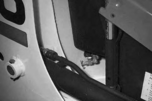
Remove Water:
Shut–off the fuel supply (Item 1) [B] (turn clockwise).
Loosen the drain at the bottom of the filter element (Item 1) [C] to drain the water from the filter.
Open the shut–off valve [B].
Replacing Filter:
Clean the area around the fuel filter.
Close the shut–off valve (Item 1) [B].
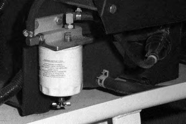
Remove the fuel filter element (Item 2) [C]
Install the new filter element.
Tighten the fuel filter.
Open the shut–off valve [B]
FUEL SYSTEM (Cont’d)
Removing Air From The Fuel System
After replacing the fuel filter element or when the fueltank has run out of fuel, the air must be removed from the fuel system before starting the engine.
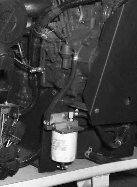
Be sure the engine is cool.
Open the rear door.
Open the vent plug (Item 1) [A] on top of the fuel filter head.
Operate the hand pump (Item 2) [A] until fuel flows from the vent plug with no air bubbles.
Tighten the vent plug.
Operate the hand pump (Item 1) [A] until it feels solid. Move the engine speed control to minimum RPM. Open the valve (Item 3)[A] and squeeze thehand pump several times.
Start the engine.
When the engine runs smoothly, close the valve (Item 3) [A].
Close the rear door.
Engine Lubrication System
Checking Engine Oil
Check the engine oil level every day before starting the engine for the work shift.
Open the rear door and remove the dipstick (Item 1) [A]
Keep the oil level between the marks on the dipstick. Use a good quality motor oil that meets API Service Classification of CD or better (See Oil Chart below). Install the dipstick and close the rear door.
Oil Chart
RECOMMENDED SAE VISCOSITY NUMBER (LUBRICATION OILS FOR DIESEL ENGINE CRANKCASE)
C° –34–29–23–18–13–7–1+4+10+15+21+27+32+38+43+49
SAE 40W or 20W–50
SAE 10W–30
SAE 15W–40
SAE 30W
* SAE 5W–30
SAE 20W–20
SAE 10W
SYNTHETIC OIL Use recommendation from Synthetic Oil Mfgr.
–30–20–100+10+20+30+40+50+60+70+80+90+100+110+120
TEMPERATURE RANGE ANTICIPATED BEFORE NEXT OIL CHANGE (DIESEL ENGINES MUST USE API CLASSIFICATION CD, CF4, CG4 )
* Can be used ONLY when available with appropriate diesel rating.
Replacing Oil And Filter
See the SERVICE SCHEDULE Page 29 for the service interval for replacing the engine oil and filter. Run the engine until it is at operating temperature. Stop the engine.
Open the rear door.
Remove the cap from the end of the hose and drain the oil into a container (Item 1) [B]. Dispose of used oil in an environmentally safe manner.
Remove the filter (Item 2) [B]
Clean the filter housing surface.
Put clean oil on the gasket of the new filter. Install the filter and hand tighten.
Install the cap on the drain hose.
ENGINE LUBRICATION SYSTEM (Cont’d)
Replacing Oil And Filter (Cont’d)
Remove the oil filler cap (Item 1) [A].
Use a good quality motor oil that meets API Service Classification of CD or better (See Oil Chart Page 40.).
Fill to capacity. (See SPECIFICATIONS Page 69.)
Start the engine and let it run for about 5 minutes. Check for leaks at the filter. Check the oil level. Add oil until the level is at the FULL mark on the dipstick.
Install the oil filler cap (Item 1) [A].
NOTE:DO NOT overfill the crankcase.
Record the operating hours of the loader on the decal inside the rear door.
Close the rear door before operating the loader.
Engine Cooling System
Check the cooling system every day to prevent overheating, loss of performance or engine damage.
Wear safety glasses to prevent eye injury when any of the following conditions exist:
• When fluids are under pressure.
• Flying debris or loose material is present.
• Engine is running
• Tools are being used.
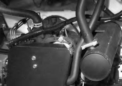
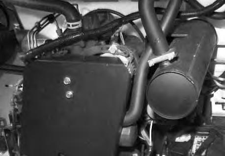
Cleaning The Cooling System
Open the rear door.
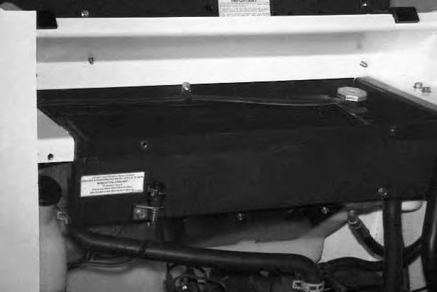
Remove the access panel from the blower housing(Item 1) [A]
Remove the rear grill. (See REAR GRILL Page 36)
Use air pressure or water pressure to remove the debris in the area of the radiator and oil cooler [B]
Install the rear grill and close the rear door.
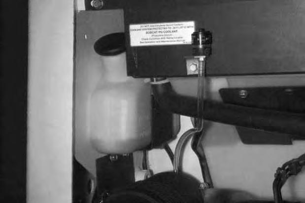
Checking The Coolant Level
Open the rear door.
The coolant recovery tank (Item 1) [C] must be at the FULL COLD mark when engine is cool.
Propylene Glycol
NOTE:The loader is factory filled with propylene glycol coolant. DO NOT mix propylene glycol with ethylene glycol.
Add premixed coolant; 47% water and 53% propylene glycol to the recovery tank if the coolant level is low.
One gallon and one pint of propylene glycol mixed with one gallon of water is the correct mixture of coolant to provide a –34°F (–37°C) freeze protection.
Use a refractometer to check the condition of propylene glycol in your cooling system.
Close the rear door before operating the loader.
ENGINE COOLING SYSTEM (Cont’d)
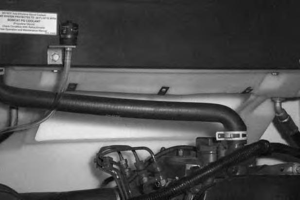
Replacing The Coolant
Remove the rear grill. (See REAR GRILL Page 36.)
Open the rear door.
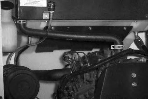
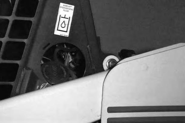
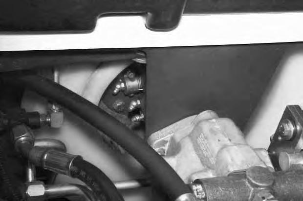
Remove the radiator cap (Item 1) [A].
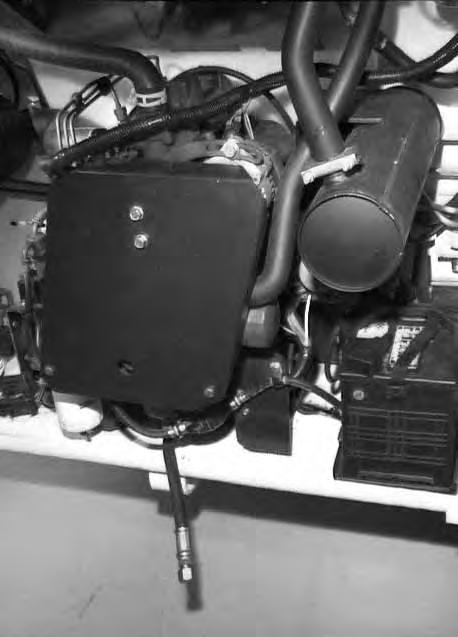
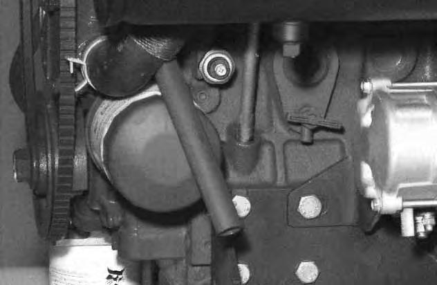
Connect a hose to the coolant drain valve (Item 1) [B] (located behind the engine oil filter) or use a funnel to keep coolant from getting into the engine compartment.
Open the valve and drain all the coolant into a container.
Close the valve.
Fill the radiator with premixed coolant and install the radiator cap. (See Checking the Coolant Level Page 42 for premix recommendations.)
Fill the coolant recovery tank 1/3 full with premixed coolant (Item 1) [C]
Check the radiator cap for correct pressure rating or overheating can result.
Check for leaks in the cooling system. Check for worn or damaged hoses, clamps or radiator. Check for loose or worn water pump belt.
Replace damaged parts immediately to prevent leaksand overheating.
Install the radiator cap and the rear grill and close the rear door.
Always use the correct ratio of water to antifreeze.
Too much antifreeze reduces cooling system efficiency and may cause serious premature engine damage.
Too little antifreeze reduces the additives which protect the internal engine components; reduces the boiling point and freeze protection of the system.
Always add a premixed solution. Adding full strength concentrated coolant can cause serious premature engine damage.
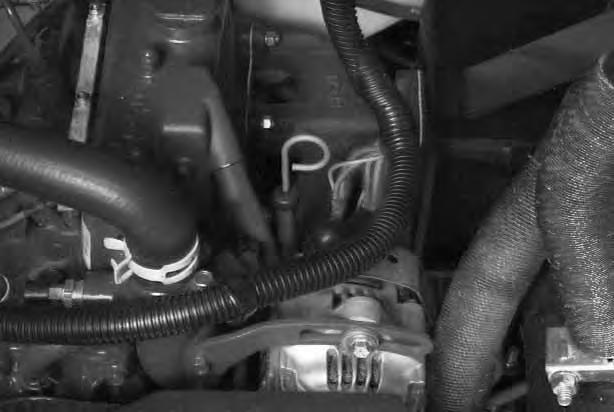
Alternator Belt Adjustment
Stop the engine.
Open the rear door.
Remove the engine belt shield.
Loosen the mounting bolt (Item 1) and adjustment bolt (Item 2) [A]
Move the alternator to set the belt tension at 5/16’’ (8 mm) movement between pulleys with 15 pounds (67 N) of force [B]
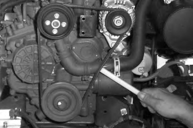

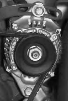
Tighten the adjustment bolt and mounting bolt.
Close the rear door.
Install the engine belt shield.
Electrical System
Description
The loader has a 12 volt, negative ground alternator charging system.
The electrical system is protected by seven fuses located in the engine compartment. The fuses will protect the electrical system when there is an electrical overload.
Find the reason for the overload before starting the engine again.
Electrical System Maintenance
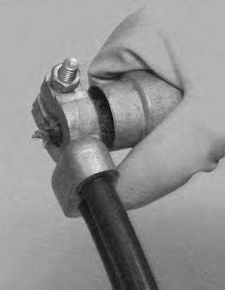
The battery cables must be clean and tight. Remove acid or corrosion from the battery and cables with a baking soda and water solution [C]
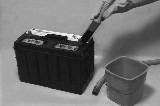
Cover the terminals of the battery with Melroe Battery Saver (P/N 886398) to prevent corrosion. Do not use silicone based products.
Install the terminal covers.
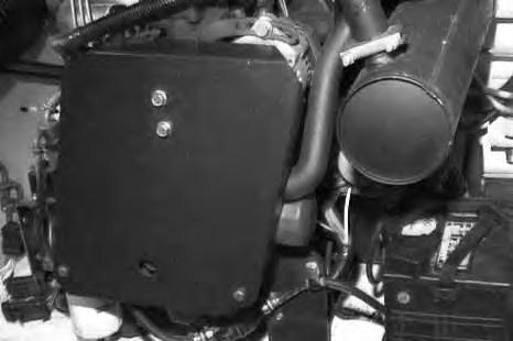
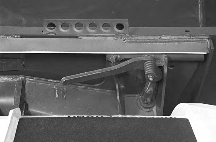
Fuse Location
The fuses are located under the fuse covers (Item 1) [D] located in the engine compartment near the air cleaner.
The fuse decal [D] shows the size and location of each fuse.
ELECTRICAL SYSTEM (Cont’d)
Using A Booster Battery (Jump Starting)
Damage to the alternator can occur if:
• Engine is operated with battery cables disconnected.
• Battery cables are connected when using a fast charger or when welding on the loader (Remove both cables from the battery).
• Extra battery cables (booster cables) are connected wrong.
If it is necessary to use an extra battery to start theengine, BE CAREFUL! There must be one person in the operator’s seat and one person to connect and disconnect the battery cables.
The key switch must be OFF.
The battery must be 12 volt.
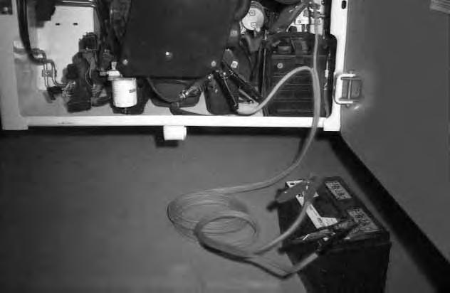
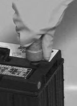
Connect the end of the first cable to the positive terminal (+) of the booster battery (Item 1) [A]. Connect the other end of the same cable to the loader battery positive (+) terminal (Item 2) [A].
Connect the end of the second cable to the negative terminal (–) of the booster battery (Item 3) [A]. Connect the other end of second cable to the engine ground (Item 4) [A]
Keep the cables away from moving parts. Start the engine.
After the engine has started, remove the ground cable connected to the engine first.
Remove the cable connected to the loader battery.
Batteries contain acid which burns eyes and skin on contact. Wear goggles, protective clothing and rubber gloves to keep acid off body.
In case of acid contact, wash immediately with water. In case of eye contact get prompt medical attention and wash eye with clean, cool water for at least 15 minutes.
If electrolyte is taken internally drink large quantities of water or milk! DO NOT induce vomiting. Get prompt medical attention.
W–2065–1296
Keep arcs, sparks, flames and lighted tobacco away from batteries. When jumping from booster battery make final connection (negative) at engine frame.
Do not jump start or charge a frozen or damaged battery. Warm battery to 60°F. (16°C.) before connecting to a charger. Unplug charger before connecting or disconnecting cables to battery. Never lean over battery while boosting, testing or charging.
Battery gas can explode and cause serious injury.
ELECTRICAL SYSTEM (Cont’d)
Removing And Installing The Battery
Batteries contain acid which burns eyes and skin on contact. Wear goggles, protective clothing and rubber gloves to keep acid off body.
In case of acid contact, wash immediately with water. In case of eye contact get prompt medical attention and wash eye with clean, cool water for at least 15 minutes.
If electrolyte is taken internally drink large quantities of water or milk! DO NOT induce vomiting. Get prompt medical attention.
W–2065–1296
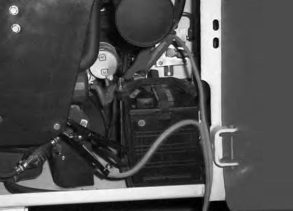
Open the rear door.
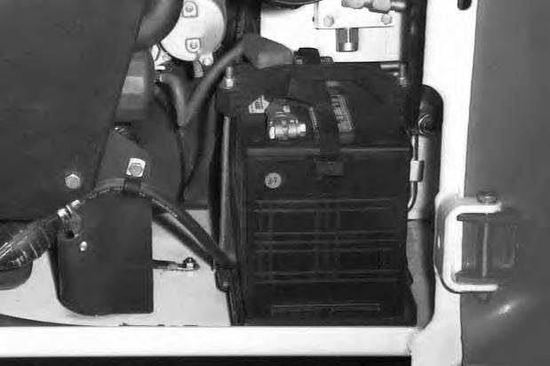
Disconnect the negative (–) battery cable (Item 1) [A]
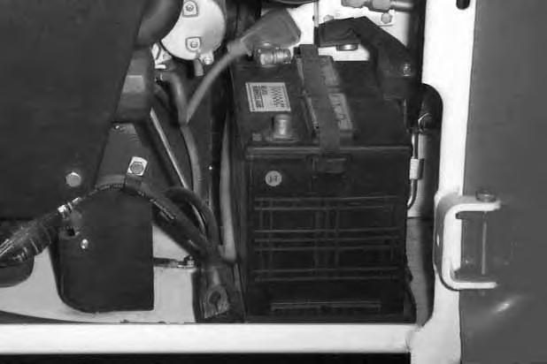
Remove the battery holddown clamp (Item 1) [B]
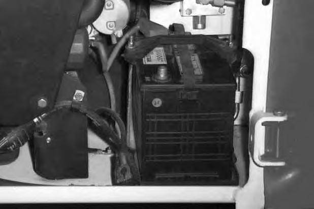
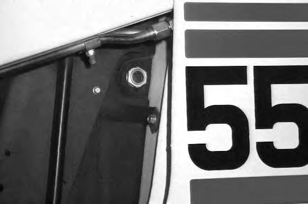
Disconnect the positive (+) battery cable (Item 1) [C]
Remove the battery from the loader.
Always clean the battery terminals and cable ends when installing a new battery [D]
Do not touch any metal parts with the battery terminals.
Connect and tighten the battery cables. Connect the negative (–) cable last to prevent sparks.
Inspect the battery holddown to be sure that it is in good condition. If it is cracked or broken, replace it.
Close the rear door.
HYDRAULIC/HYDROSTATIC SYSTEM
The hydraulic and hydrostatic systems use the same hydraulic fluid reservoir.
The system has an engine driven pump that suppliesfluid to the control valve, lift and tilt cylinders.
Fluid also goes from the control valve to the hydrostatic transmission pumps to provide charge pressure and cooling.
A filter is installed on the right side of the engine compartment. This filter cleans the fluid for the hydrostatic transmission.
The oil cooler is under the radiator. The oil cooler coolsthe hydraulic fluid before it returns to the hydrostatic pump.
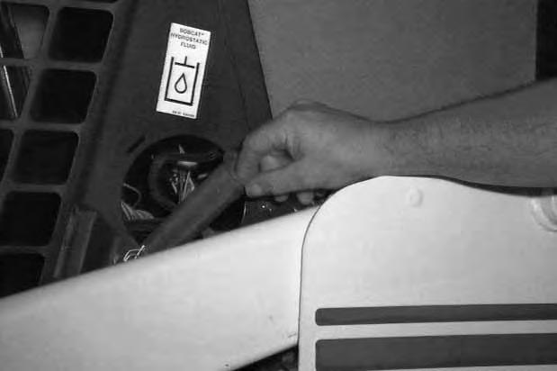
Checking And Adding Fluid
Use only recommended fluid in the hydraulic/hydrostatic system. (See SPECIFICATIONS Page 69.)
Put the loader on a level surface.
Lower the lift arms and put the attachment flat on the ground.
Stop the engine.
Hydraulic fluid must show in the sight gauge (Item 1)[A]
Remove the filler cap (Item 1) [B]
Add fluid to the reservoir until it shows in the sight gauge [A]
Install the filler cap [B]
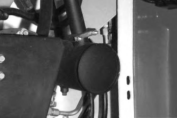
HYDRAULIC/HYDROSTATIC SYSTEM (Cont’d)
Replacing The Hydraulic/Hydrostatic Filter
See the SERVICE SCHEDULE Page 29 for the correct service interval to replace the filter.
Stop the engine. Open the rear door.
Clean the area around the filter housing and remove the filter element (Item 1) [A]
Clean the surface where the filter seal contacts the filter housing.
Lubricate the rubber gasket with grease. Install the filter element and hand tighten.
Operate the loader and check for leaks at the filter.
Check fluid level in the reservoir and add as needed.
Close the rear door.
Replacing Hydraulic Fluid
See the SERVICE SCHEDULE Page 29 for the service interval to replace the fluid. Replace the fluid if it becomes contaminated and after any major repairs.
Remove the filler cap (Item 1) [B].
Remove the screen (Item 1) [C]
Wash the screen in clean solvent. Install the screen in the fill pipe.
Remove the hose and remove the fluid from the hydraulic reservoir.
Remove the filter element.
Install a new filter element (See procedure above).
Add hydraulic/hydrostatic fluid to the reservoir. (See SPECIFICATIONS Page 69 for the correct fluid.) DO NOT fill above the sight glass.
Install the filler cap.
Operate the loader.
Stop the engine.
Check the fluid level and add as needed.
AVOID INJURY OR DEATH
Always clean up spilled fuel or oil. Keep heat, flames, sparks or lighted tobacco away from fuel and oil. Failure to use care around combustibles can cause explosion or fire which can result in injury or death.
W–2012–0290
Spark Arrestor Muffler
See the SERVICE SCHEDULE Page 29 for correct service interval to clean the spark arrestor muffler.
Do not operate the loader with a defective exhaust system.
This machine is factory equipped with a U.S.D.A. Forestry Service approved spark arrestor muffler. To keep it in working condition, dump the spark chamber after every 100 hours of operation.
If this machine is operated in California on flammable forest, brush or grass covered land, it must be equipped with a spark arrestor attached to exhaust system and maintained in working order. Failure to do so will be in violation of California State Law, Section 4442, PRC.
Refer to local laws and regulations for spark arrestor requirements.
Never use machine in atmosphere with explosive dust or gases or where exhaust can contact flammable material. Failure to obey warnings can cause injury or death.
Stop engine and allow the muffler to cool before cleaning the spark chamber. Wear safety goggles. Failure to obey can cause serious injury.
When an engine is running in an enclosed area, fresh air must be added to avoid concentration of exhaust fumes. If the engine is stationary, vent the exhaust outside. Exhaust fumes contain odorless, invisible gases which can kill without warning.
Stop the engine. Open the rear door.
Cover the battery with a fire retardent material.
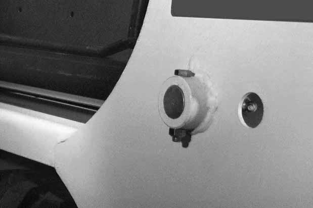
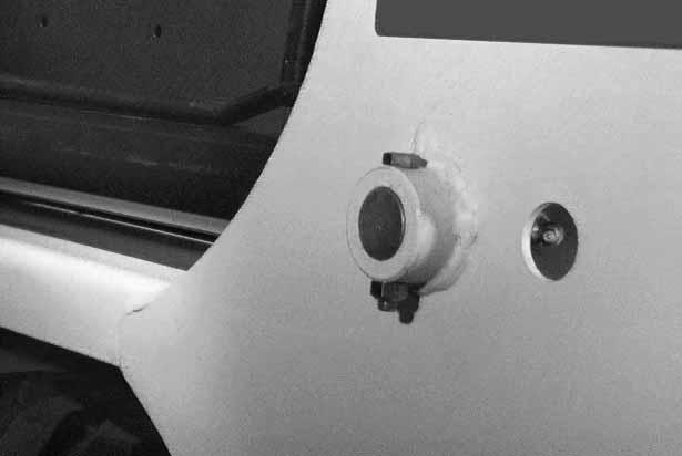
Remove the plug (Item 1) [A] at the bottom of the muffler.
Start the engine.
Have a second person (wearing safety goggles) hold a block of wood over the outlet of the muffler (with the engine running) for about 10 seconds.
Stop the engine and install the plug.
Close the rear door.
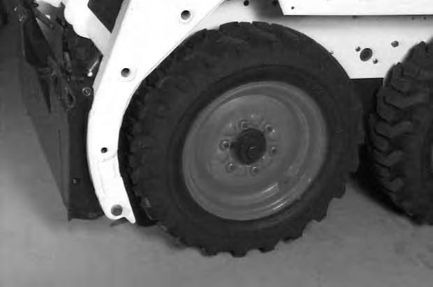
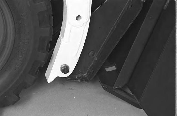
Tire Maintenance
Wheel Nuts
See the SERVICE SCHEDULE Page 29 for the service interval to check the wheel nuts. The correct torque is 105–115 ft.–lbs. (142–156 Nm) [A].
Tire Rotation
Check the tires regularly for wear, damage and pressure. (See SPECIFICATIONS Page 69 for the correct tire pressure.)
Rear tires usually wear faster than front tires. To keep tire wear even, move the front tires to the rear and rear tires to the front [B].
It is important to keep the same size tires on each side of the loader to avoid excessive wear. If different sizes are used, each tire will be turning at a different rate and cause excessive wear. The tread bars of all the tires must face the same direction.
Recommended tire pressure must be maintained to avoid excessive tire wear and loss of stability and handling capability. Check for the correct pressure before operating the loader.
Tire Mounting
Tires are to be repaired only by an authorized person using the proper procedures and safety equipment. Tires and rims must always be checked for correct size before mounting. Check rim and tire bead for damage.
The rim flange must be cleaned and free of rust. The tire bead and rim flange must be lubricated with a rubber lubricant before mounting the tire, avoid excess pressure which can rupture the tire and cause serious injury or death. During inflation of the tire, check the tire pressure frequently to avoid over–inflation.
Inflate tires to the MAXIMUM pressure shown on the side wall of the tire. DO NOT mix brands of tires used on the same loader.
FINAL DRIVE TRANSMISSION (CHAINCASE)
Checking And Adding Oil
The chaincase contains the final drive sprockets and chains and uses the same type of oil as the hydraulic / hydrostatic system. (See SPECIFICATIONS Page 69 for the correct oil.)
Drive the loader onto a level surface. Stop the engine.
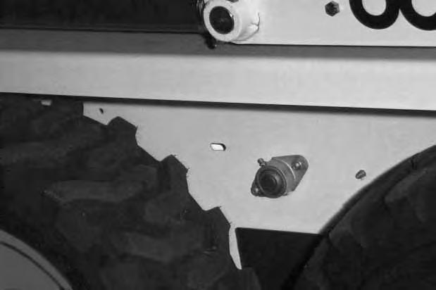
Remove the plug (Item 1) [C].
If oil can be reached with the tipof the your finger through the hole, the oil level is correct.
If the level is low, add oil through the check plug hole until the oil flows from the hole.
Install and tighten the plug.
Do not inflate tires above specified pressure. Failure to use correct tire mounting procedure can cause an explosion which can result in injury or death.
Lubricating The Bobcat Loader
Lubricate the Bobcat loader as specified in theSERVICE SCHEDULE Page 29 for the best performance of the loader.
Record the operating hours each time you lubricate the Bobcat loader.
Always use a good quality lithium based multi–purpose grease when you lubricate the loader. Apply until extra grease shows.
Lubricate the following locations on the loader:
LUBRICATING THE BOBCAT LOADER (Cont’d)
5.Rod End Tilt Cylinder [A].
6.Bob–Tach Pivot Pin (both sides) [A]
7.Bob–Tach Wedge (both sides) [A]
8.250 Hours: Steering Lever Shaft Bearings (2) [B] (The opposite end is lubricated under the cab.).
Put oil in the hole of the cross shaft where the right and left steeriing shafts meet under the cab.
Pivot Pins
All lift arm and cylinder pivots have a large pin held in position with a retainer bolt and lock nut (Item 1) [C]
Check that the lock nuts are tightened to 18–20 ft.–lbs. (24–27 Nm) torque.
BOB–TACH Inspection And Maintenance
Move the Bob–Tach levers to engage the wedges [A]. The levers and wedges must move freely.
The wedges must extend through the holes in the attachment mounting frame (Item 1) [A]
Bob–Tach wedges must extend through the holes in attachment. Levers must be fully down and locked. Failure to secure wedges can allow attachment to come off and cause injury or death.
W–2102–0588
The spring loaded wedge (Item 1) [A] must contact the lower edge of the hole in the attachment(Item 1) [B] and [C].
If the wedge does not contact the lower edge of the hole [B] and [C], the attachment will be loose and can come off the Bob–Tach.
Wedge
Wedge Must Contact Lower Edge Of Hole In The Attachment
Inspect the mounting frame on the attachment and the Bob–Tach, linkages and wedges for excessive wear or damage [D]. Replace any parts that are damaged, bent, or missing. Keep all fasteners tight.
Look for cracked welds. Contact your Bobcat dealer for repair or replacement parts.
Lubricate the wedges (SeeSERVICE SCHEDULE, Page 29 and LUBRICATION OF THE BOBCAT LOADER, Page 51).
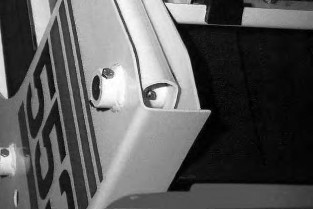
Auxiliary Control Lockbolt
The auxiliary control has a lockbolt (Item 1) that must be removed to use the optional auxiliary hydraulics.
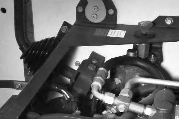
Raise the operator cab. (See Raising the Operator Cab Page 32.)
Remove the nut and bolt (Item 1) [A] at the right hand steering lever.
Lower the operator cab. (SeeLowering The Operator Cab Page 32.)
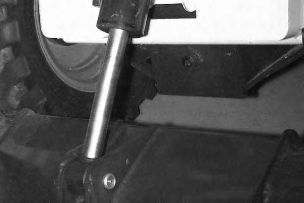
U–JOINT LUBRICATION
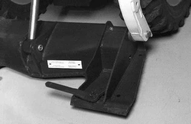
See the SERVICE SCHEDULE Page 29 for the correct service interval to lubricate the U–joint grease fittings (three) (Item 1) [B].
Raise the operator cab. (See Raising the Operator Cab Page 32.)
Use the special U–joint grease (P/N 6599719) for correct lubrication for the U–joint.
Lower the operator cab. (SeeLowering The Operator Cab Page 32.)
Troubleshooting
The following information identifies loader problems which can occur most often. Service procedures for correcting loader problems can be found in this manual on the pages indicated. Some procedures are marked D/S (Dealer Service) and must be performed only by qualified Bobcat service personnel.
Instructions are necessary before operating or servicing machine. Read Operation & Maintenance Manuals, Handbook and signs (decals) on machine. Follow warnings and instructions in the manuals when making repairs, adjustments or servicing. Check for correct function after adjustments, repairs or service. Failure to follow instructions can cause injury or death
W–2003–0797
Troubleshooting The Engine
Problem Correction Cause
Engine won’t turn over with starter.
Battery has low charge.
Cables loose or dirty.
Damaged starter, solenoid or wiring.
Charge battery and find cause for loss of charge.
Clean and tighten the battery cables.
Check the starting circuit. Repair as needed.
Engine turns with starter, but is difficult to start.
Wrong starting procedure.
Air in the fuel.
Ignition system is damaged.
Auxiliary control lever in continuous flow or lift is in float
No fuel in tank.
Vent in fuel filter cap is plugged.
Dirt or water in fuel system.
Fuel filter is dirty.
Hole or leak in fuel line.
Weak battery.
Wrong oil in engine.
Cylinder compression is low.
Engine has overheated.
Poor fuel quality.
Use correct starting procedure.
Remove air from the fuel system.
Check & repair as needed.
Move controls to neutral position.
Add fuel.
Clean the vent.
Repair as needed.
Install a new filter.
Repair as needed.
Charge or replace battery.
See Oil Specifications.
Recondition the engine.
Check cooling system.
Use fresh, good quality fuel.
Engine has little power or runs rough.
Injectors are not working correctly.
Dirt, water or air in fuel system.
Engine is hot.
Restricted exhaust.
Repair as needed.
Clean and repair as needed.
See Engine Overheats.
Clean exhaust system.
TROUBLESHOOTING THE ENGINE (Cont’d)
Problem Correction Cause
Engine has little power or runs rough (Cont’d)
Engine overheats.
Dirty air cleaner.
Cylinder compression is low.
Restriction in cooling air flow.
Blower shroud damaged or missing.
Engine is overheated.
Install new element. Recondition the engine.
Check for debris on radiator grill.
Check shroud and repair or replace as needed.
Run at full throttle.
Troubleshooting The Drive System
Problem Correction Cause
No drive on both sides.
Hydraulic fluid is low.
Damaged hydraulic pump.
Check fluid level. Add as needed.
Check condition of pump and replace as needed.
No drive on one side.
Hydrostatic system is damaged. Control linkage is disconnected.
Hydrostatic system is damaged.
Check hydrostatic system.
Repair linkage.
Check hydrostatic system and make repair as needed.
Machine pulls to one side. Loader moves when levers are in neutral.
System is overheating.
Wrong tire pressure. Steering linkage interference.
Hydrostatic system is damaged. Steering linkage out of adjustment.
Hydraulic fluid level is low.
Cooling system is dirty. Air restricted.
Low charge pressure (transmission light on).
Auxiliary control in continuous flow position.
Loader is overloaded.
Check all tires for correctpressure.
Check steering linkage and adjust as needed.
Check system. Repair as needed. Adjust steering linkage.
Check fluid level and add as needed.
Clean cooling system. Check for debris on radiator grill.
Check by–pass valve.
Move controls to neutral position.
Use correct size attachment.
Parking brake will not hold.
D/S = Dealer Service Only
Hydrostatic system is damaged. – – –
Check system and make repair. –
Troubleshooting The Hydraulic System
Problem Correction Cause
No hydraulic action.
No hydraulic fluid.
Pedals are disconnected. Relief valve is damaged.
Hydraulic pump is damaged.
Hydraulic fluid is too thick.
Check fluid level and add as needed.
Check linkage repair as needed.
Replace the relief valve.
Check pump. Replace as needed.
Let machine warm up.
Hydraulic action is rough.
Hydraulic action is slow.
Hydraulic fluid level is low.
Pedal is hitting floor or debris under pedal. Cylinders leak internally.
Hydraulic pump is damaged. Control valve is damaged.
Check fluid level and add as needed.
Check adjustment. Remove debris.
Check condition of cylinders and repair as needed.
Check pump. Replace as needed.
Check valve and repair asneeded.
Hydraulic cylinders leak fluid.
D/S = Dealer Service Only
Hydraulic fluid is too thick. Damage to cylinder rods or seals.
Let machine warm up.
Repair cylinders.
BOBCAT INTERLOCK CONTROL SYSTEM (BICS™)
Troubleshooting Chart
The following list shows the effects which can happen to the loader, and the probable causes when the BICS Controller lights are off or flashing. Have service procedures performed ONLY BY QUALIFIED BOBCAT SERVICE PERSONNEL.
Effect on
Operation of Loader
Flashing Indicator Means System Problem
(See Your Bobcat Dealer for Service)
IndicatorWhen Light Is Number of LightLight ON Light OFF OFFFlashes
SeatOperator in SeatNo Operator in SeatLift and tilt functions will not operate.
Cause
2Seat sensor circuit shorted to battery voltage*.
3Seat sensor circuit shorted to ground
Seat BarSeat Bar DownSeat Bar UpLift, tilt and traction2Seat bar sensor circuit shorted to functions will not battery voltage*. operate.
3Seat bar sensor circuit shorted to ground.
ValveControl Valve CanControl ValveLift and tilt functions1Valve output circuit is open. Be UsedCannot Be Usedwill not operate.2Valve output circuit shorted to battery voltage*.
3Valve output circuit shorted to ground.
3Valve output circuit is not grounded.
TractionLoader can beLoader cannot beLoader cannot be1Traction lock hold coil circuit is open. moved forward &moved forward andmoved forward and2Traction lock hold coil circuit shorted backward.backward. backward. to battery voltage*.
3Traction lock hold coil circuit shorted to ground.
4Traction lock pull coil circuit is open.
5Traction lock pull coil circuit is shorted to battery voltage*.
6Traction lock pull coil circuit is shorted to ground.
PowerBICS ControllerBICS Controller isLift, tilt and traction is operatingnot operatingfunctions will not correctly.correctly. operate.
NOTES:
(1)If the seat and/or seat bar sensor circuits are open, the corresponding lights will be OFF. If one of the lights stay OFF, check the circuit for continuity. See Inspection & Maintenance Instructions in Preventive Maintenance section.
(2)If all five lights flash repeatedly, the voltage supply is greater than 16 volts or less than 9 volts.
(3)Flashing patterns will repeat every 3.25 seconds.
(4)If seat indicator light does not go ON, check for debris, dirt or objects under or behind the seat. The Seat Sensor Override♦ can be used if the seat sensor cannot be activated.
♦ Only on later loaders, and early loaders which have had BICS Controller and switch replaced.
NOTE: If the Seat Bar is lowered before the seat sensor is activated, a 10 second delay will occur before the valve and traction lights come on. (only loaders with BICS controller S/N’s above 200,000 will have this delay.)
* Normal BICS operating voltage is less than the electrical system voltage. If voltage is more, the circuit is shorted to system voltage.
Machine Sign Translations
6579528)
6702302)
MACHINE SIGNS (DECALS)
Machine signs (decals) are an essential part of the loader (See Page xiv & xv). This section provides French and Spanish translations of the machine signs that are in English. The Operator’s Handbook is also available in a combination English, French, German, Spanish, Italian and Dutch editions.
IMPORTANTE (SPANISH)
ESTA MAQUINA ESTA EQUIPADA POR LA FABRICA CON UN AMORTIGUADOR DE CHISPAS DEL SILENCIADOR, APROBADO POR EL SERVICIO DE SILVICULTURA DEL U.S.D.A. (DEPARTMENTO DE AGRICULTURA DE LOS ESTADOS UNIDOS).
ES NECESARIO LIMPIAR ESTE AMORTIGUADOR DE CHISPAS DEL SILENCIADOR PARA MANTENERLO EN BUEN ESTADO. HAY QUE DARLE SERVICIO AL AMORTIGUADOR, VACIANDO LA CAMARA DE CHISPAS CADA 100 HORAS DE FUNCIONAMIENTO.
SI ESTA MAQUINA ESTA DESTINADA PARA TRABAJAR EN BOSQUES, MATORRALES O EN PASTOS QUE PUEDAN INCENDIARSE, ENTONCES TIENE QUE ESTAR EQUIPADA CON UN AMORTIGUADOR DE CHISPAS EN EL SISTEMA DEL ESCAPE Y TIENE QUE MANTENERSE EN PERFECTAS CONDICIONES DE TRABAJO. ES NO HACER ESTO CONSTITUYE UNA INFRACCION DE LA LEY ESTATAL DE CALIFORNIA, SECCION 4442, PRC.
REFIERASE A LAS LEYES Y REGULACIONES LOCALES EN CUANTO A LOS REQUISITOS DEL AMORTIGUADOR DE CHISPAS.
IMPORTANT (FRENCH)
CETTE CHARGEUSE EST EQUIPPEE A LA SORTIE DE L’USINE D’UN SILENCIEUX PARA–ETINCELLES APPROUVE PAR LE SERVICE DES EAUX ET FORETS DES ETATS–UNIS.
IL EST INDISPENSABLE D’EFFECTUER UN ENTRETIEN REGULIER DE CE PARE–ETINCELLES AFIN DE LE GARDER EN BON ETAT DE MARCHE. L’ENTRETIEN CONSISTE A VIDER LA CHAMBRE A ETINCELLES TOUTES LES 100 HEURES DE MARCHE.
SI CET ENGIN EST UTILISE SUR UN TERRAIN COUVERT D’ARBRES, DE BROUSSAILLES, OU D’HERBAGES INFLAMMABLES, IL FAUT INSTALLER LE PARE–ETINCELLES ET LE GARDER EN BON ETAT DE MARCHE.
CONSULTER LES REGLEMENTATIONS LOCALES APPLICABLES.
ADVERTENCIA (SPANISH)
EVITE HERIDAS O LA MUERTA
• Mantenga le puerta cerrada excepto para dar servicio.
• Mantenga el motor limpio y que no tenga material inflamable.
• Mantenga el cuerpo. objetos sueltos y la ropa lejos de los conductores eléctricos, piezas móviles, piezas calientes y del escape.
• No use el cargador en lugares donde hay polvo o gases explosivos o materiales inflamables cerca al escape.
• Todos los gases del escape pueden matar. Ventile siempre el lugar de trabajo.
• No use nunca éter o líquido del arranque en los motores de diesel que tienen tapones encendedores. Use solamente las ayudas para el arranque que sean aprobados por el fabricante del motor.
• Escapes de líquido bajo presión pueden penetrat en la piel y causar heridas graves. Se requiere atención médica inmediata. Use gafas. Use cartón para revisar si hay fugas.
• El ácido de la batería puede causar quemaduras severas, use gafas. Si el ácido hace contacto con los ojos, la piel o la ropa, lávelos bién con agua. Si el contactor fuel en los ojos, lávelo bién y vaya al médico.
• Las baterias producen gas inflammable y explosivo. Mantenga lejos, arcos, chispas, llamas y tabaco encendido.
• Para arranque con batería auxiliar, conecte de último el cable negativo al motor del cargador (nunca la batería). Despues de hacer el arranque con cables, quite peimero la conección negativa del motor.
AVERTISSEMENT (FRENCH)
EVITER LES BLESSURES, VOIRE LA MORT
• Maintenir la porte arrière fermée, sauf pour les entretiens.
• Débarasser le moteur de toute matière inflammable.
• Maintenir le corps, les objets non attachés et les vêtements à l’écart des contacts électriques, des pièces mobiles et brûlantes et de l’échappement.
• Ne pas utiliser la machine dans un endroit chargé de poussières ou de gaz explosifs, et où l’échappement risque de toucher des matériaux inflammables.
• Les gaz d’échappement peuvent être mortels. Toujours aérer.
• Les liquides sous pression peuvent pénétrer au travers ed la peau et causer de graves blessures. Consult er immédiatement un médecin Porter des lunettes de sécurité. Utiliser du carton pour repérer les fuites.
• L’acide des batteries provoque de graves brûlures, porter des lunettes de sécurité. S’il entre en contact avec le s yeux, la peau ou les vêtements, rincer généreusement à l’eau. Pour les yeux, appeler un médecin.
• Les batteries dégagent des gaz inflammables et explosifs. Tenir les arcs électriques les étincelles, les flammes et las cigarettes allumées à l’écart.
• En cas de démarrage par pontage, effectuer le dernier branchement (Câble négatif) au moteur (jamais à la batterie). Pour débrancher, déconnecter d’abord le câble négatif du moteur.
• Ne jamais utiliser d’éther ou de liquide de démarrage sur un moteur diesel avec des bougies de préchauffage. N’employer que les aides au démarrage approuvées par le fabricant.
ADVERTENCIA (SPANISH)
EVITE HERIDAS O LA MUERTE
NO USE NUNCA EL CARGADOR SIN LEER LAS INSTRUCCIONES.
LEA EL MANUAL DEL OPERATIO, EL MANUAL DE SERVICIO Y LA GIA DEL OPERARIO.
NO VIAJE O DE LA VUELTA CON LOS BRAZOS DE ELEVACION ARRIBA.
CARGUE, DESCARGUE Y DE LA VUELTA ESTANDO EN UN SITIO PLANO Y NIVELADO.
NO EXCEDA LA CAPACIDAD NOMINAL DE FUNCIONAMIENTO (VEA EL AVISO EN EL CARGADOR).
USE LA BARRA DEL ASIENTO. ASEGURESE BIEN EL CINTURON DE SEGURIDAD.
NUNCA MODIFIQUE EL EQUIPO NI USE ADITAMENTOS QUE NO ESTEN APROBADOS POR LA COMPAÑIA MELROE.
MANTENGA LOS PIES EN LOS PEDALES.
EN LA PENDIENTES, MANTENGA EL EXTREMO PESADO DE CARGADOR EN POSICION ASCENDENTE.
ANTES DE BAJARSE DEL CARGADOR
1.BAJE LOS BRAZOS DE ELEVACION. COLOQUE EL ADITAMENTO BEIN EN EL SUELO.
2.PARE EL MOTOR.
3.PONGA EL FRENO.
4.LEVANTE LA BARRA DEL ASIENTO. MUEVA LOS PEDALES HASTA QUE AMBOS SE TRABEN.
ATTENTION (FRENCH)
EVITER LES BLESSURES OU LA MORT
NE JAMAIS SE SERVIR DE LA CHARGEUSE SANS INSTRUCTIONS.
LIRE LE MANUEL DE L’OPERATEUR EL D’ENTRETIEN AINSI QUE LE GUIDE D’UTILISATION.
NE PAS SE DEPLACER NI VIRER AVEC LE BRAS RELEVES. CHARGER, DECHARGER ET VIRER SUR UN SOL PLAT ET HORIZONTAL.
NE PAS DEPASSER LE CAPACITE NOMINALE (CONSULTER L’AUTOCOLLANT APPOSE SUR LA CARGEUSE).
UTILISER L’ARCEAU DE SECURITE. ATTACHER SOIGNEUSEMENT LA CEINTURE DE SECURITE.
NE JAMAIS MODIFIER L’EQUIPEMENT NI SE SERVIR D’ACCESSOIRES QUE NE SONT PAS APPROUVES PAR MELROE COMPANY.
MAINTENIR LES PIEDS SUR LES PEDALES.
DANS LES PENTES, TOUJOURS MAINTENIR LA PARTIE LA PLUS LOURDE DE LA CHARGEUSE VERS LE HAUT.
POUR QUITTER LA CHARGEUSE:
1.ABAISSER LES BRAS DE LEVAGE. POSER L’EQUIPEMENT A PLATE SUR LE SOL.
2.ARRETER LE MOTEUR.
3.ENCLENCHER LE FREIN DE STATIONNEMENT.
4.RELEVER L’ARCEAU DE SECURITE. DEPLACER LES PEDALES JUSQU’A CE QU’ELLES SOIENTE TOUTES DEUX VERROILLEES.
Translations not available at time of printing.
ADVERTENCIA (SPANISH)
EVITE HERIDAS O LA MUERTE
LLEVE LA CARGA EN POSICION BAJA
EL NO OBEDECER ESTA ADVERTENCIA PUEDE CAUSAR LADEAMIENTO O VUELCOS O PERDIDAD DE LA CARGA Y DE LA VISIBILIDAD.
AVERTISSEMENT (FRENCH)
EVITER DES BLESSURES OU LA MORT
TENIR LA CHARGE VERS LE BAS.
LE NON RESPECT PEUT ENTRAINER UN BASCULEMENT OU UN RENVERSEMENT DE LA MACHINE, UNE PERTE DE LA CHARGE OU DE VISIBILITE.
PELIGRO (SPANISH)
EVITE LA MUERTE
• MANTENGASE RETIRADO DE ESTA AREA CUANDO LOS BRAZOS DE ELEVACION ESTAN ELEVADOS, A MENOS QUE ESTEN TRABADOS POW EL TOPE.
• EL MOVER EL PIE DEL PEDAL O FALLA DE UNA PIEZA PUEDEN CAUSAR LA CAIDA DE LOSBRAZOS DE ELEVACION.
DANGER (FRENCH)
EVITER LA MORT
• EVITER CETTER ZONE LORSQUE LES BRAS D E LEVAGE RELEVÉS NE SONT PAS ASSURÉS PAR DES ARRETS DE BRAS DE LEVAGE.
• UNE PEDALE ACTIONNÉE OU UNE PICE DEFECTUEUSE. PEUT PROVOQUER L’ABAISSEMENT DES BRAS DE LEVAGE.
ADVERTENCIA (SPANISH)
EL CILINDRO CONTIENE GAS BAJO ALTA PRESION. EL ABNRIR EL CILINDRO PUEDE SOLTAR LA VARILLA Y CAUSAR HERIDAS O LA MUERTE.
AVERTISSEMENT (FRENCH)
LES VERINS RENFERMENT UN GAZ SOUS PRESSION. NE JAMAIS OUVRIR UN VERIN CAR LA TIGE RISQUE DE S’ECHAPPER BRUTALEMENT ET DE CAUSER DES BLESSURES OU MEME LA MORT.
PELIGRO (SPANISH)
EVITE LA MUERTE
• EL FORZAR EL IMPLEMENTO CONTRA EL SUELO HACE QUE LA RUEDDAS DELANTERAS SE ELEVEN
• NUNCA SE META DEBAJO NI ALCANCE NADA DEBAJO DE LOS BRAZOS DE ELEVACION O DEL CILINDRO DE ELEVACION SIN QUE ESTE INSLADO U N TOPE APROBADO EN LOS BRAZOS DE ELEVACION
DANGER (FRENCH)
EVITER LA MORT
• L’ACCESSOIRE PEUT ETRE APPUYE CONTRE LE SOL ET SOULEVER LES ROUES AVANT.
• NE JAMAIS ALLER SOUS NI METTRE LES MAINS SOUS LES BRAS OU LE VERIN DE LEVAGE SANS QU’UN ARRET DE BRAS DE LEVAGE APPROUVE SOIT INSTALLE.
Loader Specifications Specifications
Dimensions are given for loader equipped with standard tires and dirt bucket and may vary with other bucket types. All dimensions are shown in inches. Respective metric dimensions are given in millimeters enclosed by parentheses.
Where applicable, specification conform to SAE or ISO standards and are subject to change without notice.
Changes of structure or weight distribution of the loader can cause changes in control and steering response and can cause failure of the loader parts.
Hand lever throttle; Key–Type starter switch. Pull cable shutdown.
Two independent hydrostatic systems controlled by two hand operated steering levers.
Secondary Brake One of the hydrostatic transmissions
Parking Brake Mechanical Disc, foot operated pedal. ENGINE Make/Model
Horsepower (SAE)
Gross: 22.5 HP (16,8 kW) Net: 19.5 HP(14,5 kW)
Hi Idle 1125–1175 RPM
Low Idle 3100–3200RPM
Torque @ 1800 RPM (SAE)
Gross: 43 ft.–lbs.(58,2 Nm) Net: 41 ft.–lbs.(55,5 Nm)
Number of Cylinders Three
56.6 cu.–in (928 cm 3)
Bore/Stroke2.95/2.76 (74,9/70,1)
LubricationPressure System W/Filter Crankcase Ventilation External
Air Cleaner Dry replaceable paper cartridge w/safety element
Ignition Compression Diesel


