12 minute read
INSTRUMENT PANEL


Front Panel [A]
1. TRACTION LOCK OVERRIDE BUTTON – Allows you to use the steering levers to move the loader forward or backward when using the backhoe attachment or for loader service. (See Page 5.)
2. SEAT SENSOR OVERRIDE BUTTON (If Equipped) (Functions Only When The Seat Bar Is Down)–Allows operator, when seated with the seat bar lowered, to use lift, tilt, and traction functions if the seat sensor cannot be activated. (See Page 15.)
3. KEY SWITCH – For starting & stopping the engine.
4. TRANSMISSION WARNING LIGHT – Low transmission charge pressure, hydraulic filter needs replacement or high fluid temperature. Stop the engine if the light comes ON.
5. ENGINE WARNING LIGHT – Low engine oil pressure or high coolant temperature. Stop the engine if the light comes ON.
6. PREHEAT BUTTON – For preheating the engine (glow plugs) before starting the engine.
7. LIGHT SWITCH (Opt./FA) – Controls the available work and travel lights.
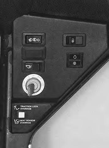
8. BUCKET LEVEL SWITCH (Opt./FA) – Controls the ON/OFF function of the available bucket position valve.
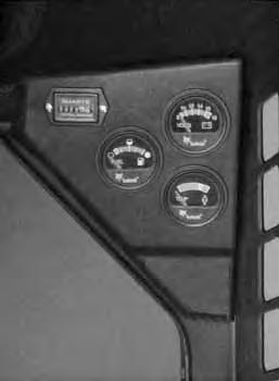
9. HOURMETER – Records the total operating hours of the loader.
10. FUEL GAUGE – Shows the amount of fuel in the fuel tank.
11. VOLTMETER – Shows the condition of the battery and the rate of charge.
12. ENGINE TEMPERATURE GAUGE – Shows the engine coolant temperature.
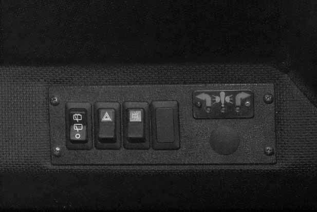
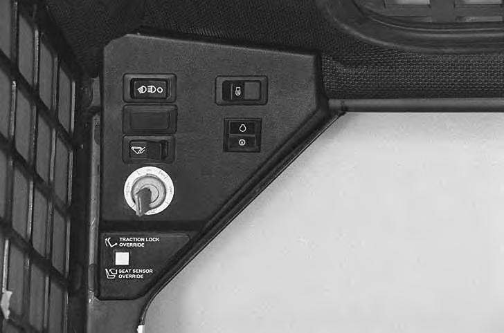
Side Console* [B]
1. REAR WIPER/WASHER (FA) – Controls operation of the available rear window wiper and washer.
2. HAZARD SWITCH/HAZARD INDICATORS (Opt./FA) – Controls the available hazard lights. (Hazard Lights is a separate available accessory.) Both panel indicators blink for hazard condition when the hazard switch is ON. A red light indicates fuse out for taillights, headlights, work lights, etc.
3. BEACON OR STROBE SWITCH (Opt./FA) –Controls the available flashing beacon or strobe light.
* Can be installed if you have a Deluxe Cab or a Cab Enclosure installed.
Opt . – Factory Installed Opt ion FA – F ield Installed Accessory – See your Bobcat loader dealer about available Field Accessories.
BOBCAT INTERLOCK CONTROL SYSTEM (BICS™)
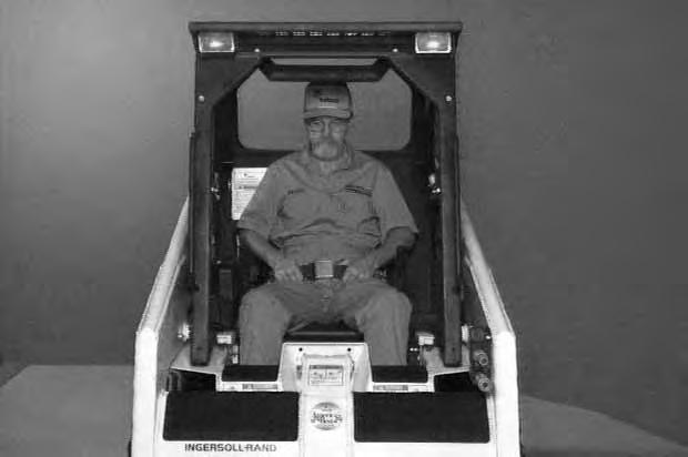
The Bobcat Interlock Control System (BICS ™) requires the operator to be seated in the operating position with the seat bar fully lowered before the lift, tilt and traction functions can be operated. The seat belt must be fastened anytime you operate the loader.
Avoid Injury Or Death
The Bobcat Interlock Control System (BICS) must deactivate the lift, tilt and traction drive functions. If it does not, contact your dealer for service. DO NOT modify the system.
W–2151–0394
The lift, tilt and traction drive functions are interlockedwith the seat bar. The lift and tilt functions are interlocked with the seat.
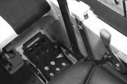
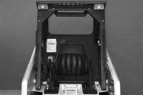
The BICS controller is located inside the cab; behind and to the right of the operator’s seat [A]
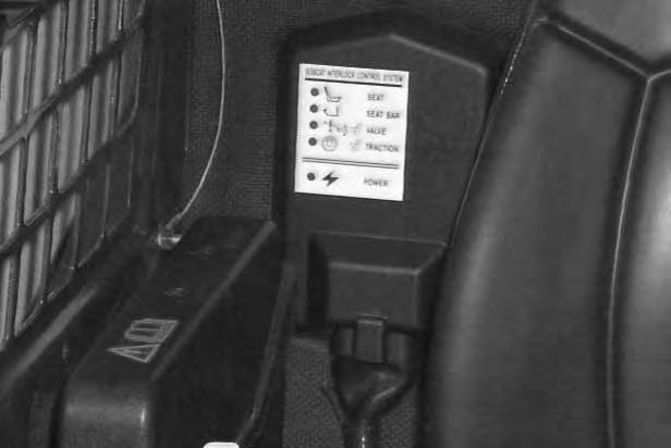
There are five green lights on the BICS controller and all must be ON to operate the loader.
The light functions are as follows [A]:
1. SEAT – ON when operator is in the seat.
2. SEAT BAR – ON when the seat bar is in down position.
3. VALVE – ON when lift and tilt hydraulic functions can be used.
4. TRACTION – ON when loader can be moved forward or backward.
5. POWER – ON when the controller is operating correctly.
NOTE:If any of the lights are off or blinking, see SYSTEMS ANALYSIS Section , BICS
Troubleshooting Chart Page 55 or, see BICS Inspection and Maintenance Instructions Page 35.
BOBCAT INTERLOCK CONTROL SYSTEM (BICS™) (Cont’d)
Lift Arm By–Pass Control
The lift arm by–pass control knob (Item 1) [A] is used to lower the lift arms if the lift arms can not be lowered during normal operation.
With the operator in the seat, seat belt fastened and the seat bar fully lowered, pull and hold the by–pass control knob (Item 1) [A] up. Push the top (toe) of the left (lift) pedal. The lift arms will slowly lower.
Traction Lock Override
(Functions Only When The Seat Bar Is Raised)
There is a traction lock override button (Item 1)[B] on the left hand instrument panel which will allow you to use the steering levers to move the loader forward and backward when using the backhoe attachment or for loaderservice.
• Press the button once to unlock traction drive (green traction light on BICS controller will be ON).
• Press the button a second time to lock the traction drive (green traction light on BICS controller will be OFF).
NOTE:The traction lock override button will unlock the traction drive when the operator is NOT in the seat and the seat bar is raised.
The traction lock override button will function if brake pedal is in the engaged or disengaged position.
Seat Sensor Override (If Equipped)
(Functions Only When The Seat Bar Is Down)
Seat Sensor Override button (Item 1)[B] allows operator, when seated with the seat bar lowered, to uselift, tilt, and traction functions if the seat sensor cannot be activated.
If seat indicator light on the BICS Controller does not go on, check for debris, dirt, or objects under or behind seat.
Avoid Injury Or Death
Before you leave the operator’s seat:
• Lower the lift arms, put the attachment flat on the ground.
• Stop the engine.
• Engage the parking brake.
• Raise seat bar, move pedals until both lock.
W–2045–1086
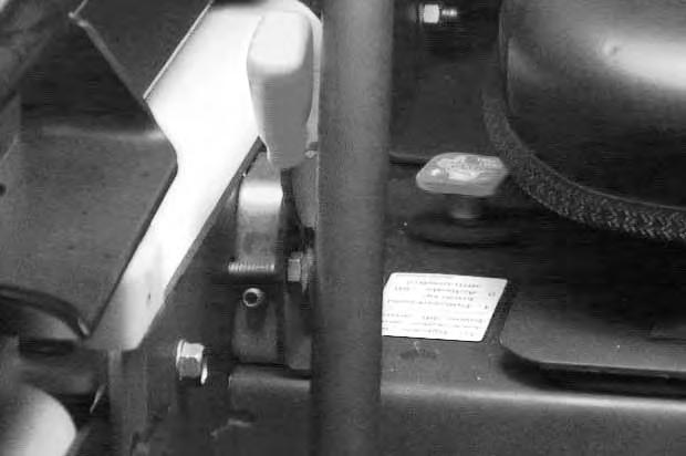
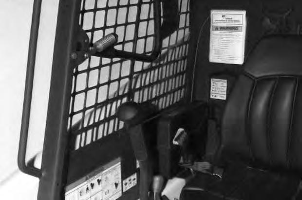
Engine Speed Control
The engine speed control (Item 1) [A] is at the right side of the operator’s seat. Engine speed is controlled by moving the engine speed control forward to increase the engine RPM and backward to decrease the engine RPM.
Parking Brake
Engage the parking brake by pushing on the top (toe) of the pedal [B]. The traction drive system will be locked.
To release the parking brake, push down on the bottom (heel) of the pedal [C].
NOTE:If the loader will not move when operator is in the operating position with brake pedal released or when traction lock override button is pushed, move the steering levers either forward or backward a small amount to unlock the traction drive.
Steering Levers
Avoid Injury Or Death
When operating the machine:
• Keep the seat belt fastened snugly.
• The seat bar must be lowered.
• Keep your feet on the pedal controls.
W–2046–0595
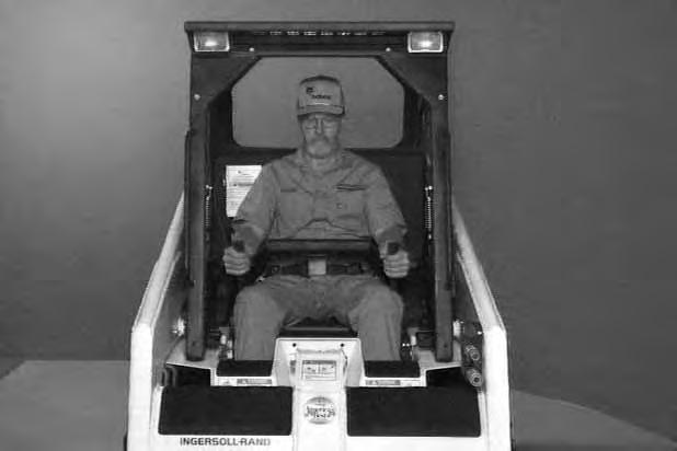
The steering levers (Item 1) [A] are on the right and left side in front of the seat
For safe control of the loader always move the levers slowly and smoothly. Only a small movement is necessary to move the loader.
The steering levers control forward and reverse travel of the loader [B]
Forward Travel: Push both levers forward.
Reverse Travel: Pull both levers backward.
Normal Turning : Move one lever farther forward than the other.
Fast Turning : Push one lever forward and pull the other lever backward.
For slow travel speed, push the levers forward only a small amount.
To increase travel speed, push the levers farther forward.
For maximum pushing force, push the levers forward only a small amount with the engine at full RPM.
Stopping The Bobcat Loader
When the steering levers are moved to NEUTRAL POSITION, the hydrostatic transmission will act as a service brake to stop the loader.
Reverse
RIGHT TURN 553 Bobcat Loader Operation & Maintenance Manual –7–
Left Turn
Seat Bar Restraint System
The seat bar restraint system has a pivoting seat bar (Item 1) [A] with arm rests and has spring loaded interlocks for the lift and tilt control functions.
The operator controls the use of the seat bar. The seat bar in the down position helps to keep the operator in the seat.
The interlocks require the operator to lower the seat bar in order to operate the hand controls.
When the seat bar is up, the lift and tilt control functions are locked when returned to the NEUTRAL POSITION.
Avoid Injury Or Death
When operating the machine:
• Keep the seat belt fastened snugly.
• The seat bar must be lowered.
• Keep your feet on the pedal controls.
W–2046–0595
Before you leave the operator’s seat:
• Lower the lift arms, put the attachment flat on the ground.
• Stop the engine.
• Engage the parking brake.
• Raise the seat bar, move hand controls until both lock.
The seat bar system must lock the lift and tilt controls in neutral when the seat bar is up. Service the system if hand controls do not lock correctly.
W–2153–0594
SEAT BAR RESTRAINT SYSTEM (Cont’d)
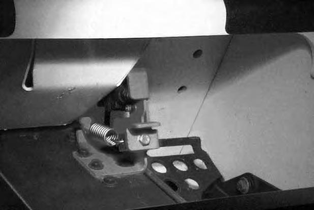
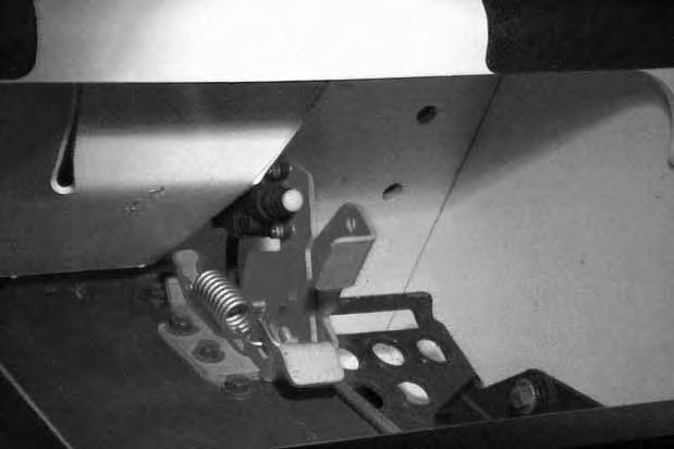
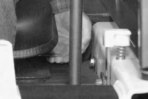
The spring loaded interlocks (Item 1) [A] control the locking and unlocking functions of thefoot pedal controls.
The interlocks (Item 1) [A] require the operator to lower the seat bar (Item 2) [A] which allows the operator to move the foot pedals to control the lift and tilt functions.
When the seat bar is lowered, it pushes the interlock (Item 1) [A] down on both sides, releasing the pedal linkages (Item 3) [A] from the interlocks.
The foot pedals will pivot in both directions when the interlock is down.
AVOID INJURY OR DEATH
Before you leave the operator’s seat:
• Lower the lift arms, put the attachment flat on the ground.
• Stop the engine.
• Engage the parking brake.
• Raise seat bar, move pedals until both lock.
W–2045–1086
AVOID INJURY OR DEATH
The seat bar system must lock the lift and tilt control pedals in neutral when the seat bar is up. Service the system if pedals do not lock correctly.
W–2105–1285
When the seat bar is raised, spring forces raise the interlocks [B].
The foot pedals will not pivot when the interlock is up.
Refer to SEAT BAR RESTRAINT SYSTEM, Inspection & Maintenance Page 34.
MC–01668
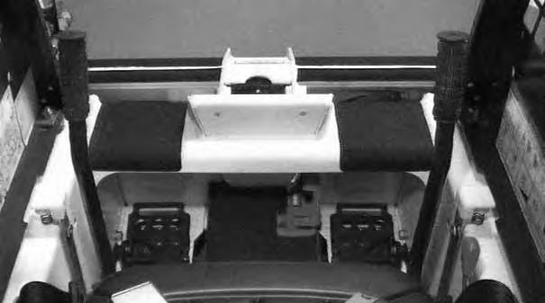
Hydraulic Controls
Foot Pedals
Keep both feet on pedals while operating machine. Failure to do so can cause serious injury.
W–2002–1285
Put your feet on the pedals and KEEP THEM THERE any time you operate the loader.
Two foot pedals (Item 1) [A] control the hydraulic cylinders for the lift and tilt functions.
Lift Arm Operation
The left pedal controls the lift arms. Push on the bottom (heel) (Item 2) [A] of the pedal to raise the lift arms.
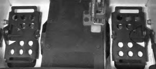
Push on the top (toe) (Item 3)[A] of the pedal to lower the lift arms.
Lift Arm Float Position
Push the top (toe) (Item 3) [A] of the pedal all the way forward until it locks into float position
Use the float position of the lift arms to level loose material while driving backward.
Push the bottom (heel) of the lift pedal to unlock from the float position.
Tilt Operation (Bucket)
The right pedal controls the action of the bucket. Push the top (toe) (Item 4) [A] of the pedal to tilt the bucket forward.
Push the bottom of the pedal (heel) (Item 5) [A] to tilt the bucket backward.
Bucket Position Valve Operation (If Equipped)
The function of the bucket position valve is to keep the bucket in the same approximate position it is placed in before beginning the upward lift cycle.
Bucket positioning functions during the upward lift cycle only.
The bucket positioning function can be turned OFF with the bucket level switch. (See Page 3.)
HYDRAULIC CONTROLS (Cont’d)
Auxiliary Hydraulics (If Equipped)
Avoid Burns
Hydraulic fluid, tubes, fittings and quick couplers can get hot when running machine and attachments. Be careful when connecting and disconnecting quick couplers.
W–2220–0396
Quick Couplers (Flush Face)
To Connect: Remove any dirt or debris from the surface of both the male and female coupler halves, and from the outside diameter of the male coupler. Visually check the couplers for corroding,cracking, damage, or excessive wear, if any of these conditions exist, the coupler(s) must be replaced [A].
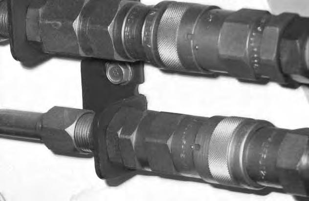
Install the male half coupler into the female half coupler. Full connection is made when the ball release sleeve slides forward on the female coupler and the sleeve is rotated so that the locking pins (Item 1) [B] and the groove (Item 2) [B] do NOT align (Locked Position). This will prevent accidental disconnection.
NOTE:If the locking pins and grooves (Item 3) [B] are aligned, accidental disconnection is possible.
To Disconnect: Rotate the ball release sleeve so that the grooves are aligned with thepins (Item 3) [B] in the female coupler.
Hold the male coupler. Retract the sleeve on the female coupler until the couplers disconnect.
NOTE:Caps and plugs are not used with flush face couplers.
Diesel fuel or hydraulic fluid under pressure can penetrate skin or eyes, causing serious injury or death. Fluid leaks under pressure may not be visible. Use a piece or cardboard or wood to find leaks. Do not use your bare hand. Wear safety goggles. If fluid enters skin or eyes, get immediate medical attention from a physician familiar with this injury.
W–2072–0496
HYDRAULIC CONTROLS (Cont’d)
Auxiliary Hydraulics (Cont’d)
AVOID BURNS
Hydraulic fluid, tubes, fittings and quick couplers can get hot when running machine and attachments. Be careful when connecting and disconnecting quick couplers.
W–2220–0396
The right steering lever (Item 1) [B] is also the control lever for the front auxiliary hydraulics [A].
Move the right steering lever to the left or to the right to activate the auxiliary hydraulics and operate an attachment (Example: To open or close grapple teeth). Move the lever in the opposite direction to reverse the action of the attachment [B]
Move the steering lever all the way to the right (Item 2)[B] to put the control valve into the locked position for a constant flow of hydraulic fluid under pressureto the quick couplers.
NOTE:See PREVENTIVE MAINTENANCE, AUXILIARY CONTROL LOCKBOLT Page 54 to remove auxiliary control lockbolt.
Move the auxiliary control lever out of the locked position before leaving the operator cab.
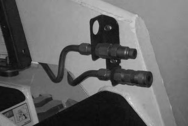
Relieving Hydraulic Pressure
Hydraulic pressure in the auxiliary hydraulic system can make it difficult to connect ot the quick couplers.
To make connecting and disconnecting attachments easier, the hydraulic pressure can be relieved.
With the engine stopped and attachment flat on the ground, move the right steering lever to the leftand to the right several times.
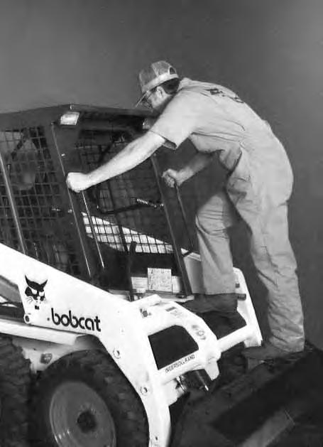
Daily Inspection
The loader must be in good operating condition [A]
Maintenance work must be done at regular intervals. Failure to do so will result in excessive wear and early failures. The Service Schedule [B] is a guide to correct maintenance of the Bobcat loader. It is located inside the rear door of the loader and also in the MACHINE SIGN
TRANSLATION Section Page 61.
Check the following items before starting each day:
• Engine Oil Level
• Hydraulic/Hydrostatic Fluid Level
• Engine Air Filter, Air System for Damage or Leaks
• Engine Coolant Level, System for Damage or Leaks
• Operator Cab, Seat Belt, Seat Bar & Pedal Interlocks
• Grease Pivot Pins (Lift Arms, Bob–Tach, Cylinders, Bob–Tach Wedges
• Tires for Wear or Damage and Correct Air Pressure
• Fuel Filter, Remove Trapped Water
• Loose or Broken Parts
• Safety Treads and Safety Signs (Decals)
• Bobcat Interlock Control System (BICS ™)
• Lift Arm Support Device
NOTE:Fluids such as engine oil, hydraulic fluid, coolants, etc. must be disposed of in an environmentally safe manner. Some regulations require that certain spills and leaks on the ground must be cleaned in a specific manner. See local, state and federal regulations for correct disposal.
Instructions are necessary before operating or servicing machine. Read Operation & Maintenance Manual, Handbook and signs (decals) on machine. Follow warnings and instructions in the manuals when making repairs, adjustments or servicing. Check for correct function after adjustments, repairs or service. Failure to follow instructions can cause injury or death [A].
W–2003–0797
Getting Ready For Operation
Read the Operation & Maintenance Manual and the Operator’s Handbook (Item 1) [A] before operating the loader.
Operator must have instructions before running the machine. Untrained operators can cause injury or death.
W–2001–1285
The Operation & Maintenance Manual and other manuals can be kept in a box provided at the right hand side of the operator seat (Item 2) [A]
Use the bucket or attachment steps, grab handles and safety treads (on top of the loader lift arm crossmember and main frame) to get on and off the loader [B]
Safety treads are installed on the Bobcatloader to provide a slip resistant surface for getting on and off the loader. Keep safety treads clean and replace when damaged. Replacement treads are available from your Bobcat loader dealer.
Pull the seat lever (Item 1)[C] and adjust the seat position for comfortable operation of the loader controls.
GETTING READY FOR OPERATION (Cont’d)
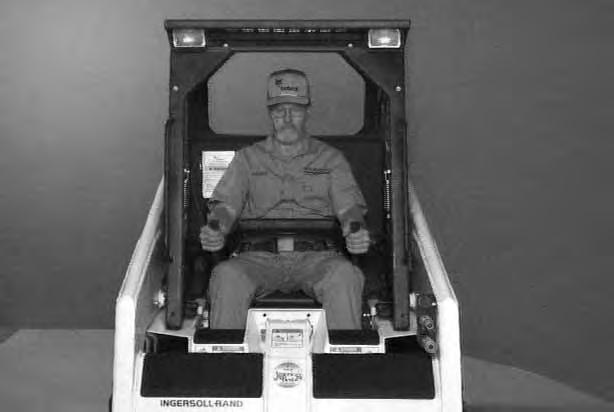
Fasten the seat belt snugly and adjust it so that the buckle is centered between your hips [A]
AVOID INJURY OR DEATH
When operating the machine:
• Keep the seat belt fastened snugly.
• The seat bar must be lowered.
• Keep your feet on the pedal controls.
W–2046–0595
Lower the seat bar [B]
Be sure the parking brake is engaged.
All controls must be in the NEUTRAL POSITION before you start the engine. (See STARTING THE ENGINE below.)
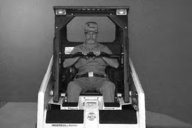
Keep your hands on the steering levers and feet on the pedals while seated in the loader [C]
Starting The Engine
WRONG
When an engine is running in an enclosed area, fresh air must be added to avoid concentration of exhaust fumes. If the engine is stationary, vent the exhaust outside. Exhaust fumes contain odorless, invisible gases which can kill without warning.
W–2050–1285
• Engines can have hot parts and hot exhaust gas. Keep flammable material away.
• Do not use machines in atmosphere containing explosive gas.
W–2051–1086
STARTING THE ENGINE (Cont’d)
Normal Starting
Adjust the seat position for comfortable operation of the foot pedals and steering levers.
Fasten the seat belt snugly and adjust it so the buckle is centered between your hips.
Lower the seat bar [A]
Put the foot pedals and steering levers in NEUTRAL POSITION (center) (Item 1) [B]
Set the engine speed control to 1/2 SPEED position(Item 2) [B]
Turn the key to the ON POSITION. The engine and transmission warning light will be ON when the key is on and the engine is stopped (Item 3) [B]
Turn the key to START POSITION (Item 4) [B] and release it when the engine starts.
Do not engage the starter for longer than 15 seconds at a time. Longer use can damage the starter by overheating. Cool the starter for one minute between uses.
When the engine starts, release the key and it will return to the RUN POSITION (Item 5) [B]
STOP THE ENGINE IF THE WARNING LIGHTS DO NOT GO OFF.
NOTE:Upon failed start, if the key is turned OFF, wait for at least three seconds before turning the key ON to reset the fuel timer module.


