43 minute read
SEAT BAR RESTRAINT SYSTEM (CONT’D)


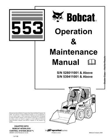
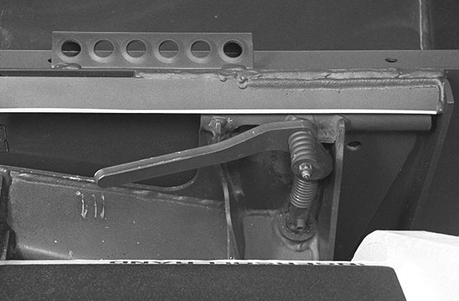
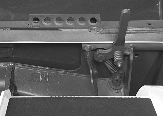
When the seat bar is raised, spring forces raise the interlocks [Figure OI-13]
The foot pedals will not pivot when the interlock is up.
(See SEAT BAR RESTRAINT SYSTEM on Page PM-11)
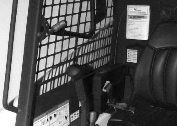
Hydraulic Controls
Foot Pedals WARNING
Keep both feet on pedals while operating machine. Failure to do so can cause serious injury.
W-2002-1285
Lift Arm Operation
The left pedal controls th e lift arms. Push the bottom (heel) of the pedal (Item 2) [Figure OI-14] to raise the lift arm.
Push on the top (toe) of the pedal (Item 3)[Figure OI14] to lower the lift arms.
Lift Arm Float Position
Push the top (toe) of the pedal (Item 3) [Figure OI-14] all the way forward until it locks into float position.
Use the float position of the lift arms to level loose material while driving backward.
Push the bottom (heel) to unlock from the float position.
Tilt Operation
The right pedal controls the movement of the bucket.
Push the top (toe) of the pedal (Item 4) [Figure OI-14] to tilt the bucket forward.
Push the bottom (heel) of the pedal (Item 5) [Figure OI-14] to tilt the bucket backward.
Bucket Position Valve Operation (If Equipped)
The function of the bucket po sition valve is to keep the bucket in the same approximate position it is placed in before beginning the upward lift cycle.
Bucket positioning functions automatically during the upward lift cycle only.
The bucket positioning func tion can be turned OFF with the bucket level switch. (See Left, Right And Accessory Panels on Page OI-3).
Put your feet on the ped als and KEEP THEM THERE any time you operate the loader.
Two foot pedals (Item 1) [Figure OI-14] control the hydraulic cylinders for the lift and tilt functions.
HYDRAULIC CONROLS (CONT’D)
Quick Couplers
Warning
Avoid Burns
Hydraulic fluid, tubes, fittings and quick couplers can get hot when running machine and attachments. Be careful when connecting and disconnecting quick couplers.
W-2220-0396
The right steering lever (Item 1) [Figure OI-16] is also the control lever for the front auxiliary hydraulics.
Move the right steering lever to the left or to the right to activate the auxiliary hydraulics and operate an attachment (Example: To open or close grapple teeth). Move the lever in the opposite direction to reverse the action of the attachment [Figure OI-16]
Move the steering lever all the way to the right (Item 2) [Figure OI-16] to put the control valve into the locked position for a constant flow of hydraulic fluid under pressure to the quick couplers.
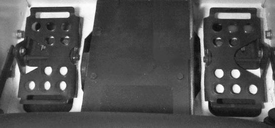
To Connect: Remove dirt or debris from the surface of both the male and female co uplers, and from the outside diameter of the male coupler. Visually check the couplers for corroding, cracking, dama ge, or excessive wear. If any of these conditions exist, the coupler(s) must be replaced [Figure OI-15]
To Disconnect: Hold the male coupler. Retract the sleeve on the female coupler until the couplers disconnect.
Warning
Diesel fuel or hydraulic fluid under pressure can penetrate skin or eyes, causing serious injury or death. Fluid leaks under pressure may not be visible. Use a piece of cardboard or wood to find leaks. Do not use your bare hand. Wear safety goggles. If fluid enters skin or eyes, get immediate medical attention from a physician familiar with this injury.
W-2072-0496
NOTE:(See AUXILIARY CONTROL LOCKBOLT on Page PM-35) to remove auxiliary control lockbolt.
Move the auxiliary control lever out of the locked position before leaving the operator cab.
Relieving Hydraulic Pressure
With the engine stopped and attachment flat on the ground, move the right steering lever to the left and to the right several times. This relieves pressure that can be trapped in the auxiliary circuit which would make it difficult to engage quick couplers from an attachment.
Daily Inspection
Figure OI-17
Maintenance work must be done at regular intervals. Failure to do so will result in excessive wear and early failures. The Service Schedule [Figure OI-17] is a guide to correct maintenance of the Bobcat loader. It is located inside the rear door of the loader and also (See SERVICE SCHEDULE (6734534) on Page MST-3).
Daily Inspection and Maintenance
•Engine Oil Level
•Hydraulic/Hydrostatic Fluid Level
•Engine Air Filter Condition Indicator, Check System for Damage or Leaks
•Engine Coolant System, Check System for Damage or Leaks
•Operator Cab and Cab Mounting Hardware
•Grease Pivot Pins (Lift Arms, Bob-Tach, Cylinders, Bob-Tach Wedges)
•Tires, Check for Wear, Damage, Correct Air Pressure
•Fuel Filter, Remove Trapped Water
•Parking Brake
•Loose or Broken Parts
•Lift Arm Support Device.
•Bobcat Interlock Control System (BICS)
•Safety Treads and Safety Signs (Decals)
•Seat Belt
NOTE:Fluids such as engine oil, hydraulic fluid, coolants, etc. must be disposed of in an environmentally safe manner. Some regulations require that certain spills and leaks on the ground must be cleaned in a specific manner. See local, state and federal regulations for correct disposal.
Instructions are necessary before operating or servicing machine. Read and understand the Operation & Maintenance Manual, Operator’s Handbook and signs (decals) on machine. Follow warnings and instructions in the manuals when making repairs, adjustments or servicing. Check for correct function after adjustments, repairs or service. Untrained operators and failure to follow instructions can cause injury or death.
W-2003-0903
Important
Pressure Washing Decals
Never direct the stream at a low angle toward the decal that could damage the decal causing it to peel from the surface.
Direct the stream at a 90 degree angle and at least 12 inches (300 mm) from the decal. Wash from the center of the decal toward the edges.
Getting Ready For Operation
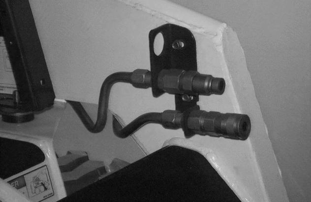
Read the Operation & Maintenance Manual and the Operator’s Handbook (Item 1) [Figure OI-18] before operating the loader.
Warning
Operator must have instructions before operating the machine. Untrained operators can cause injury or death.
W-2001-0502
The Operation & Main tenance Manual and other manuals can be kept in a box provided at the right hand side of the operator seat (Item 2) [Figure OI-18]
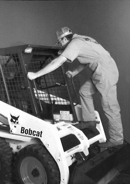
Use the bucket or attachment steps, grab handles and safety treads (on top the loader lift arm crossmember and main frame) to get on and off the loader [Figure OI-19]
Safety treads are installed on the Bobcat loader to provide a slip resistant surface for getting on and off the loader. Keep safety treads clean and replace when damaged. Replacement treads are available from your dealer.
GETTING READY FOR OPERATON (CONT’D)
Warning
Avoid Injury Or Death
When operating the machine:
•Keep the seat belt fastened snugly.
•The seat bar must be lowered.
•Keep your feet on the pedal controls.
W-2046-0595
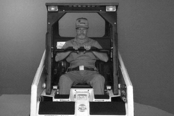
Lower the seat bar [Figure OI-22].
Be sure the parking brake is engaged.
All controls must be in NEUTRAL POSITION before you start the engine (See Normal Starting on Page OI-14).
After you start the engine, press the green PRESS TO OPERATE Button on the left instrument panel to operate lift, tilt and traction functions.
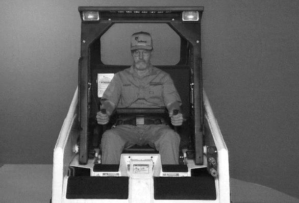
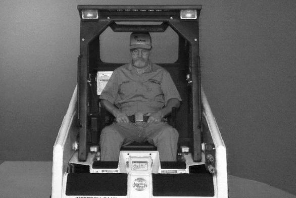
Fasten the seat belt snugly and adjust it so that the buckle is centered between your hips [Figure OI-21].
Keep your hands on the steering levers and feet on the pedals while seated in the loader [Figure OI-23]

Starting The Engine
Figure OI-24
Wrong
Warning
When an engine is running in an enclosed area, fresh air must be added to avoid concentration of exhaust fumes. If the engine is stationary, vent the exhaust outside. Exhaust fumes contain odorless, invisible gases which can kill without warning.
W-2050-1285
Wrong
Normal Starting
Figure OI-26
Warning
AVOID INJURY OR DEATH
•Engines can have hot parts and hot exhaust gas. Keep flammable material away.
•Do not use machines in atmosphere containing explosive gas.
W-2051-1086
Adjust the seat position for comfortable operation of the foot pedals and steering levers.
Fasten the seat belt snugly a nd adjust it so the buckle is centered between your hips.
Lower the seat bar [Figure OI-26]
STARTING THE ENGINE (CONT’D)
Normal Starting (Cont’d)
Important
Do not engage the starter for longer than 15 seconds at a time. Longer use can damage the starter by overheating. Cool the starter for one minute between uses.
I-2034-0284
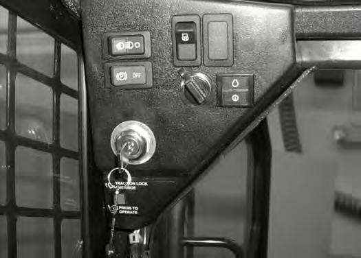
Set the engine speed control to 1/2 SPEED position (Item 2) [Figure OI-27].
Turn the key to the ON POSITION (Item 3) [Figure OI27]. The engine and transmission warning light will be ON when the key is on and the engine is stopped.
Turn the key to START POSITION (Item 4) [Figure OI27] and release it when the engine starts.
When the engine starts, release the key and it will return to the RUN POSITION (Item 5) [Figure OI-27]
STOP THE ENGINE IF THE WARNING LIGHTS DO NOT GO OFF.
NOTE:Upon failed start, if the key is turned OFF, wait for at least three seconds before turning the key ON to reset the fuel timer module.
STARTING THE ENGINE (CONT’D) Cold
Follow the steps under Normal Starting and repeat the Preheating procedure until the engine starts.
If the temperature is below 32° F(0° C), use the following procedure to make starting the engine easier:
•Replace the engine oil with the correct type and viscosity for the anticipated starting temperature. (See Checking Engine Oil on Page PM-18).
Do not use ether with glow plug (preheat) systems. Explosion can result which can cause injury, death, or severe engine damage.
W-2071-0903
•Make sure the battery is fully charged.
•Install an engine heater, av ailable from your Bobcat loader dealer
Warming The Hydraulic/Hydrostatic System
Let the engine run for a minimum of 5 minutes to warm the engine and the hydrostatic transmission fluid before operating the loader.
If the warning light comes ON when operating the loader (cold), more warm up time is needed.
Stopping The Engine
Pull the engine speed control fully backward to decrease the engine RPM.
Turn the key switch to the OFF position.
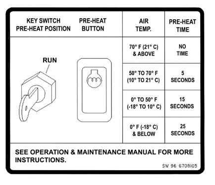
Also see Normal Starting. Turn the key switch to the RUN POSITION.
Push the PREHEAT button (Item 1) [Figure OI-28] on the left side of the instru ment panel to preheat the glow plugs.
Refer to the decal on the left side of the operator cab for operation of the preheat system [Figure OI-29]
Attachments And Buckets
Choosing The Correct Bucket WARNING
Never use attachments or buckets which are not approved by Bobcat Company. Buckets and attachments for safe loads of specified densities are approved for each model. Unapproved attachments can cause injury or death.
W-2052-0500
NOTE: Warranty is void if non-approved attachments are used on the Bobcat loader.
The dealer can identify, for each model loader, the attachments and buckets approved by Bobcat. The buckets and attachments are approved for rated operating capacity and for se cure fastening to the BobTach.
The rated operating capacity for this loader is shown on a label in the operator cab. (See Capacities on Page SPEC-5).
Rated operating capacity is determined by using a standard dirt bucket, and material of normal density, such as dirt or dry gravel. If l onger buckets are used, the load center moved forward and re duces the rated operating capacity. If very dense material is loaded, the volume must be reduced.
2.Tires may wear faster.
3.There will be a loss of stability.
4.The life of the Bobcat loader will be reduced.
Use the correct size bucket for the type and density of material being handled.
For safe handling of materials and avoiding machine damage, the attachment (or bucket) should handle a full load without going over the rated operating capacity for the loader.
Partial loads will make steering more difficult.
Pallet Forks
Exceeding the rated operating capacity can cause the following problems [Figure OI-30]:
1.Steering the loader may be difficult.
Load varies with model of pallet fork being used.
If a pallet fork attachment is used, the load center moves forward and reduces the Rated Operating Capacity.
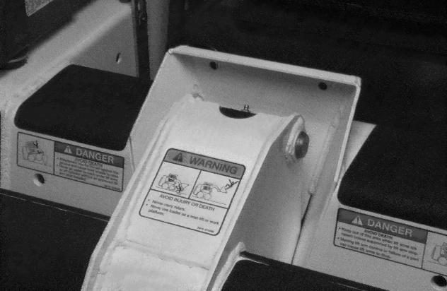
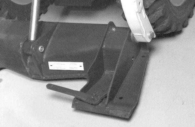
The maximum load to be carried when using a pallet fork is shown on a decal located on the pallet fork frame (Item 1) [Figure OI-31]
Warning
AVOID INJURY OR DEATH
Do not exceed rated operating capacity. Excessive load can cause tipping or loss of control.
W-2053-0887
See your Bobcat Dealer for more information about pallet fork inspection, maintenance and replacement. See your Bobcat loader dealer for Rated Operating Capacity when using a pallet fork and for other available attachments.
ATTACHMENTS AND BUCKETS (CONT’D)
Installing The Bucket or Attachment
The loader is equipped with the Bob-Tach system. The Bob-Tach is used for fast changing of buckets and attachments. See the Attachment Operation & Maintenance Manual to install other attachments
Warning
Bob-Tach levers have spring tension. Hold lever tightly and release slowly. Failure to obey warning can cause injury.
Be sure the Bob-Tach levers do not hit the bucket.
Tilt the Bob-Tach backward until the cutting edge of the bucket is slightly off the ground [Figure OI-33]
Stop the engine and exit the loader.
Pull the Bob-Tach levers all the way up (Item 1) [Figure OI-32]
Enter the loader and fasten the seat belt.
Fasten the seat belt, lower the seat bar, start the engine and press the green PRESS TO OPERATE Button.
Release the parking brake.
Lower the lift arms and tilt the Bob-Tach forward.
Drive the loader forward until the top edge of the BobTach is completely under the top flange of the bucket [Figure OI-32] (or other attachment).
Warning
AVOID INJURY OR DEATH
Before you leave the operator’s seat:
•Lower the lift arms, put the attachment flat on the ground.
•Stop the engine.
•Engage the parking brake.
•Raise seat bar, move pedals until both lock.
W-2045-1086
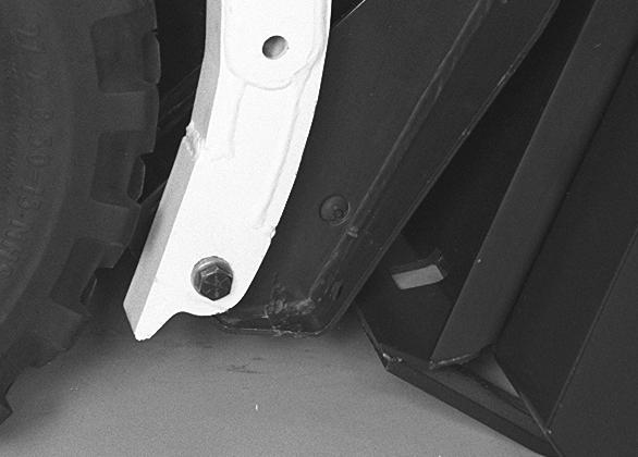
Push down on the Bob-Tach levers until they are fully engaged in the locked position [Figure OI-34]
The levers will contact the frame as shown (Item 1) [Figure OI-34] when locked.
If the lever does not engage in the locked position, see your Bobcat loader dealer for maintenance.
ATTACHMENTS AND BUCKETS (CONT’D)
Installing The Bucket or Attachment (Cont’d)
Removing The Bucket Or Attachment
The wedges (Item 1) [Figure OI-35] must extend through the holes (Item 1) [Figure OI-36] in the mounting frame of the bucket (or attachment), securely fastening the bucket to the Bob-Tach. The wedge is shown extending through the hole in the bucket [Figure OI-35]
Warning
Bob-Tach wedges must extend through the holes in attachment. Levers must be fully down and locked. Failure to secure wedges can allow attachment to come off and cause injury or death.
Put the attachment flat on the ground and lower or close the hydraulic equipment. If the attachment is hydraulically controlled (i.e.: combination bucket, backhoe, etc.), stop the engine and relieve hydraulic pressure in the auxiliary circuit. (See Relieving Hydraulic Pressure on Page OI10).
Raise the seat bar, unfasten the seat belt, engage the parking brake and exit the loader.
Pull the Bob-Tach levers all the way up [Figure OI-37].
Disconnect the hydraulic hoses, if necessary.
Enter the loader and fasten t he seat belt. Lower the seat bar, start the engine and press the green PRESS TO OPERATE Button.
Release the parking brake.
Lower the lift arms and tilt the Bob-Tach forward.
Move the loader backward, away from the bucket or attachment [Figure OI-38]
OPERATING PROCEDURE Operating With A Full Bucket
When operating on a public road or highway, always follow local regulation. For example: Slow Moving Vehicle (SMV) Sign or directional signals may be required.
Always warm up the engine and hydrostatic system before operating the loader.
Important
Machines warmed up with moderate engine speed and light load have longer life.
Operate the loader with the engine at full speed for maximum horsepower. Move the steering levers only a small amount to operate the loader.
New operators must operate the loader in an open area without bystanders. Operate th e controls until the loader can be handled at a efficient and safe rate for all conditions of the work area.
FULL BUCKET
With a full bucket, go up or down the slope with the heavy end toward the top of the slope [Figure OI-39] and [Figure OI-40].
GOING UP SLOPE
FULL BUCKET
GOING DOWN SLOPE
GOING DOWN SLOPE
With empty bucket, go down or up the slope with the heavy end toward the top of the slope [Figure OI-41] and [Figure OI-42].
Warning
AVOID INJURY OR DEATH
•Keep the lift arms as low as possible.
•Do not travel or turn with the lift arms up.
•Turn on level ground.
•Go up and down slopes, not across them.
•Keep the heavy end of the machine uphill.
•Do not overload the machine.
Failure to obey warnings can cause the machine to tip or roll over and cause injury or death.
Raise the bucket only high enough to avoid obstructions on rough ground.
OPERATING PROCEDURE (CONT’D)
Filling The Bucket
Figure OI-43
Push down on the top (toe) of the lift pedal until the lift arms are all the way down. Pu sh the top of the tilt pedal to put the cutting edge of the bucket on the ground [Figure OI-43].
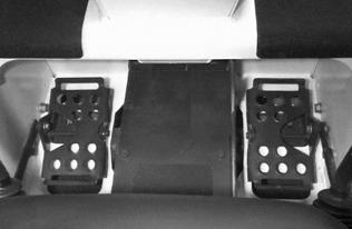
Figure OI-44
Drive slowly forward into the material. Push the bottom (heel) of the tilt pedal to raise the front of the bucket [Figure OI-44]
Warning
Load, unload and turn on flat level ground. Do not exceed rated operating capacity shown on sign (decal) in cab. Failure to obey warnings can cause the machine to tip or roll over and cause injury or death.
W-2056-1187
Drive backward away from the material.
Emptying the Bucket
Figure OI-45
Push down on the bottom (heel) of the lift pedal to raise the lift arms [Figure OI-45]. Push the top (toe) of the tilt pedal while raising the lift arms to level the bucket or attachment and help prevent material from falling off the back of the bucket or attachment.
Drive forward slowly until the bucket is over the top of the truck box or bin. Push the top of the tilt pedal until the bucket is empty [Figure OI-45]. If all the material is near the side of the truck box or bi n, push it to the other side with the bucket.
Warning
Never dump over an obstruction, such as a post, that can enter the operator cab. The machine could tip forward and cause injury or death.
W-2057-0694
OPERATING PROCEDURE (CONT’D)
Digging Into The Ground
Figure OI-46
Put the lift arms all the way down. Push the top (toe) of the tilt pedal until the cutting edge of the bucket is on the ground.
Drive forward slowly and continue to tilt the bucket down until it enters the ground [Figure OI-46]
Figure OI-47
Push the bottom (heel) of the tilt pedal a small amount to increase traction and keep an even digging depth [Figure OI-47].
Continue to drive forward until the bucket is full. When the ground is hard, raise and lo wer the cutting edge of the bucket with the tilt pedal while driving forward slowly.
Figure OI-48
Push the bottom (heel) of the tilt pedal to tilt the bucket backward as far as it w ill go when the bucket is full [Figure OI-48].
Leveling The Ground (Using Lift Arms In Float Position)
Figure OI-49
Push the top (toe) of the lif t pedal all the away forward until the pedal is in the locked position to put the lift arms in float position [Figure OI-49]
Push the tilt pedal to change the position of the cutting edge on the bucket. With the bucket tilted farther forward, there is more force on th e cutting edge and more loose material can be moved.
Important
Never drive forward when the hydraulic control for lift arms is in float position.
Drive backward to level loose material.
Push the bottom (heel) of the lift pedal to unlock from the float position.
Backfilling
Figure OI-50
Lower the lift arms and put the cutting edge of the bucket on the ground.
Drive forward to the edge of the hole and tilt the bucket forward to dump the material into the hole [Figure OI-50].
Tilt the bucket forward as so on as it is past the edge of the hole [Figure OI-50].
If necessary, raise the lift arms to empty the bucket.
Parking The Bobcat Loader
Warning
Avoid Injury Or Death
Before you leave the operator’s seat:
•Lower the lift arms, put the attachment flat on the ground.
•Stop the engine.
•Engage the parking brake.
•Raise seat bar, move pedals until both lock.
W-2045-1086
Stop the Bobcat loader on level ground.
Lower the lift arms fully and put the edge of the bucket on the ground.
Pull the engine speed control all the way backward. Turn the key switch to the OFF POSITION.
Engage the parking brake.
Lift the seat bar and make sure the foot pedals are in the locked position.
Unbuckle the seat belt. Remove the key from the switch to prevent operation of the loader by unauthorized personnel.
TRANSPORTING THE BOBCAT LOADER Loading Onto Transport Vehicle
Warning
Adequately designed ramps of sufficient strength are needed to support the weight of the machine when loading onto a transport vehicle. Wood ramps can break and cause personal injury.
W-2058-0494
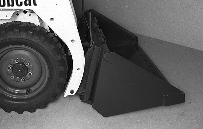
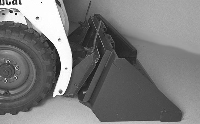
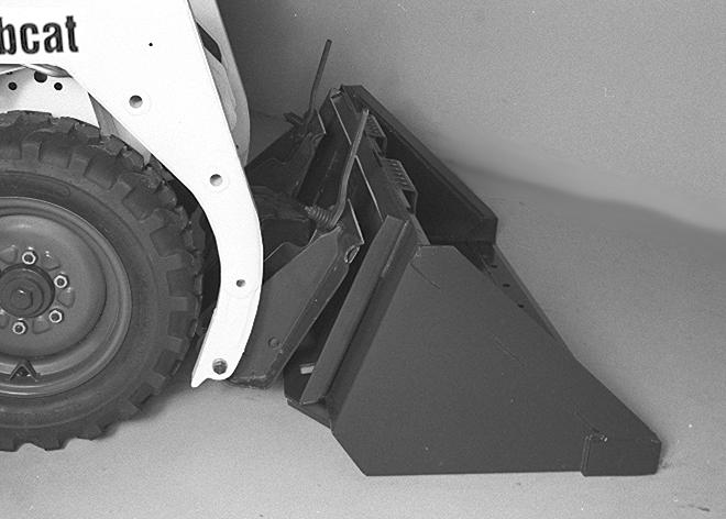
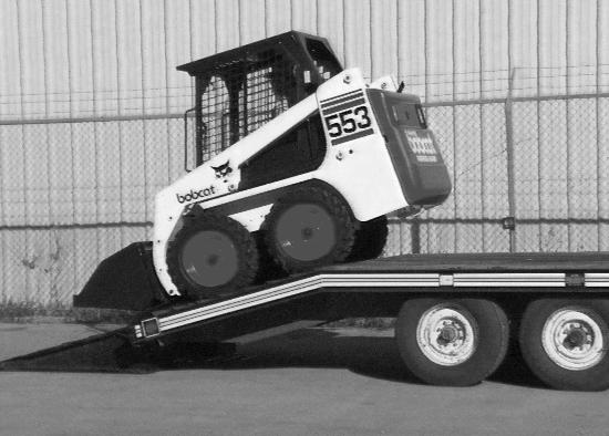
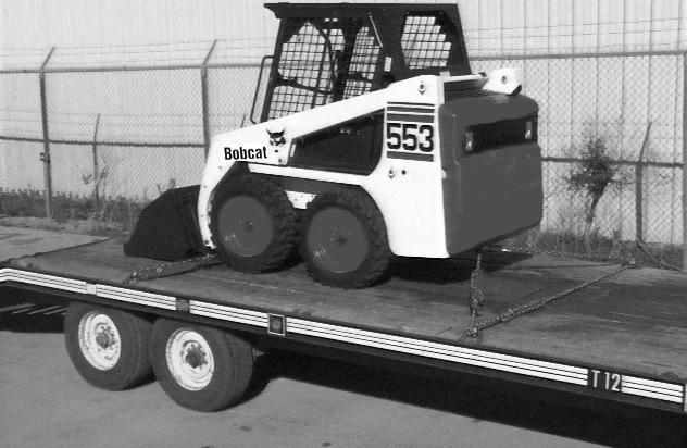
A loader with an empty bucket or no attachment must be loaded backward onto the transport vehicle [Figure OI51].
The rear of the trailer must be blocked or supported [Figure OI-51] when loading or unloading the loader to prevent the front end of the trailer from raising up.
TRANSPORTING THE BOBCAT LOADER (CONT’D)
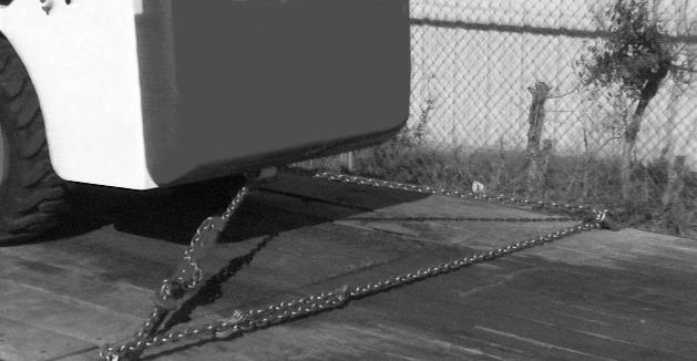
Fastening To Transport Vehicle
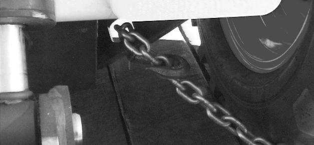
Figure OI-52
Use the following procedure to fasten the Bobcat loader to the transport vehicle to prevent the loader from moving during sudden stops or when going up and down slopes.
•Lower the bucket or attachment to the floor.
•Stop the engine.
•Engage the parking brake.
•Install chains at the front and rear of the loader as shown [Figure OI-52]
Lifting The Loader
Warning
AVOID INJURY OR DEATH
•Before lifting, check fasteners on single point lift and operator cab.
•Assemble front cab fasteners as shown in this manual.
•Never allow riders in the cab or bystanders within 15 feet (5 meters) while lifting the machine.
The loader can be lifted with the single point lift which is available as a kit from your Bobcat dealer.
Fasten the pins (Item 1) [Figure OI-53] in the kit as shown in figure.
The single point lift, supplied by Bobcat is designed to safely lift and support the Bobcat.
Towing The Loader
Important
Never attempt to start the engine by pushing or pulling. Hydrostatic pumps and motors will be damaged.
I-2001-1285
Important
Do not push or pull the machine at more than 2 MPH (3,2 km/h) or for a distance of more than 25 feet (7,6 meters) with the towing tool in place.
I-2017-0389
To prevent damage to the loaders hydrostatic system, the loader must be towed only a short distance at slow speed. (EXAMPLE: Moving th e loader onto a transport vehicle.)
Relief valve release tool set MEL1220 is available from your dealer. Tool must be installed before towing.
Raise the operator cab. (See Raising The Operator Cab on Page PM-8).
Clean the area around the hydrostatic pumps.
Lower the operator cab. (See Lowering The Operator Cab on Page PM-9).
The towing chain (or cable) must be rated at 1 and 1/2 times the weight of the loader. (See LOADER SPECIFICATIONS on Page SPEC-3).
•Turn the key switch to ON and press the traction lock override button.
•Tow the Bobcat at 2 MPH (3 ,2 km/hr) or less for not more than 25 feet (7,6 meters).
If the electrical system is not functioning, contact your Bobcat loader dealer. (Part of the brake system must be disassembled to move the loader.)
NOTE: Be sure high pressure relief valves are installed before operating the loader again.
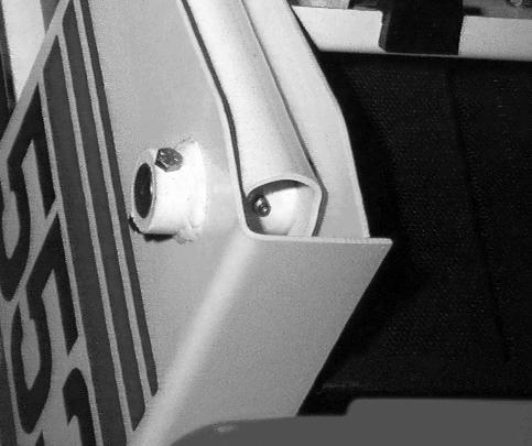
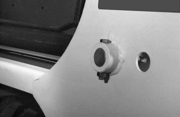
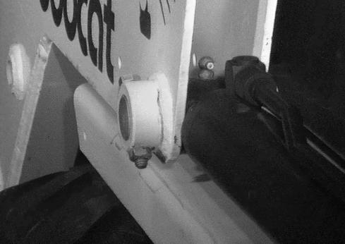
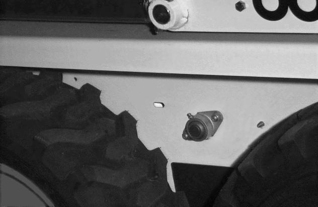
Remove the high pressure relief valve from one side of each hydrostatic pump [Figure OI-54] and install the relief valve tubes. Install the plugs and tighten.

Warning
Maintenance Safety
Instructions are necessary before operating or servicing machine. Read and understand the Operation & Maintenance Manual, Operator’s Handbook and signs (decals) on machine. Follow warnings and instructions in the manuals when making repairs, adjustments or servicing. Check for correct function after adjustments, repairs or service. Untrained operators and failure to follow instructions can cause injury or death.
W-2003-0903
Safety Alert Symbol: This symbol with a warning statement, means: “Warning, be alert! Your safety is involved!” Carefully read the message that follows.
Never service the Bobcat® Skid Steer Loader without instructions.
Use the correct procedure to lift or lower operator cab.
Cleaning and maintenance are required daily.
Have good ventilation when welding or grinding painted parts.
Wear dust mask when grinding painted parts. Toxic dust and gas can be produced.
Avoid exhaust fume leaks which can kill without warning. Exhaust system must be tightly sealed.
Disconnecting or loosening any hydraulic tubeline, hose, fitting, component or a part failure can cause lift arms to drop. Do not go under lift arms when raised unless supported by an approved lift arm support device. Replace it if damaged.
Never work on loader with lift arms up unless lift arms are held by an approved lift arm support device. Replace if damaged. Never modify equipment or add attachments not approved by Bobcat Company.
Stop, cool and clean engine of flammable materials before checking fluids.
Never service or adjust loader with the engine running unless instructed to do so in the manual. Avoid contact with leaking hydraulic fluid or diesel fuel under pressure. It can penetrate the skin or eyes.
Never fill fuel tank with engine running, while smoking or when near open flame.
Keep body, jewelry and clothing away from moving parts, electrical contact, hot parts and exhaust.
Wear eye protection to guard from battery acid, compressed springs, fluids under pressure and flying debris when engines are running or tools are used. Use eye protection approved for type of welding. Keep rear door closed except for service. Close and latch door before operating the loader.
Lead-acid batteries produce flammable and explosive gases. Keep arcs, sparks, flames and lighted tobacco away from batteries.
Batteries contain acid which burns eyes or skin on contact. Wear protective clothing. If acid contacts body, flush well with water. For eye contact flush well and get immediate medical attention.
Maintenance procedures which are given in the Operation & Maintenance Manual can be performed by the owner/ operator without any specific technical training. Maintenance procedures which are not in the Operation & Maintenance Manual must be performed ONLY BY QUALIFIED BOBCAT SERVICE PERSONNEL. Always use genuine Bobcat replacement parts. The Service Safety Training Course is available from your Bobcat dealer.
Service Schedule
Chart
Maintenance work must be done at regular intervals. Failure to do so will result in excessive wear and early failures. The service schedule is a guide for correct maintenance of the Bobcat loader.
Warning
Instructions are necessary before operating or servicing machine. Read and understand the Operation & Maintenance Manual, Operator’s Handbook and signs (decals) on machine. Follow warnings and instructions in the manuals when making repairs, adjustments or servicing. Check for correct function after adjustments, repairs or service. Untrained operators and failure to follow instructions can cause injury or death.
Service Schedule
Engine Oil Check the oil level and add as needed. Do not overfill.
Engine Air Filter and Air SystemCheck condition indicator. Service only when required. Check for leaks and damaged components.
Engine Cooling SystemClean debris from oil cooler, radiator and grill. Check coolant level COLD and add premixed coolant as needed.
Fuel Filter Remove the trapped water.
Lift Arms, Cylinders, Bob-Tach Pivot Pins and Wedges
Lubricate with multi-purpose lithium based grease.
Tires Check for damaged tires and correct air pressure. Inflate to MAXIMUM pressure shown on sidewall of tire.
Seat Bar, Control Interlocks, Seat Belt Check the condition of seat belt. Check the sear bar and control interlocks for correct operation. Clean dirt and debris from moving parts.
Bobcat Interlock Control Systems (BICS™) Check for correct function. See details in this Manual.
Safety Signs and Safety TreadsCheck for damaged signs (decals) and safety treads. Replace any signs or safety treads that are damaged or worn.
Operator Cab Check the fastening bolts, washers and nuts. Check the condition of the cab.
Indicators and Lights Check for correct operation of all indicators and lights.
Heater Filter (If Equipped)Clean or replace filter as needed.
Hydraulic Fluid, Hoses and Tubelines
Final Drive Trans. (Chaincase), Foot Pedals and Steering Levers
Check fluid level and add as needed. Check for damage and leaks. Repair or replace as needed.
Check oil level and add oil as needed. Check for correct operation. Repair or adjust as needed.
Parking Brake Check operation.
Wheel Nuts Check for loose wheel nuts and tighten to correct torque. (See TIRE MAINTENANCE, Page PM-30.)
Engine/Pump Coupler
Lubricate with multi-purpose lithium based grease.
Spark Arrestor Muffler Empty Spark Chamber.
Battery Check cables, connections and electrolyte level. Add distilled water as needed.
Engine Oil and Filter Replace oil and filter. Use CD or better grade oil and Bobcat filter. ✵
Steering Lever Pivots Grease fittings.
Fuel Filter Replace filter element.
Alternator Belt Check condition and tension. Adjust or replace as needed.
Bobcat Interlock Control System (BICS™)
Check the function of the lift arm by-pass control.
Hyd./Hydro. Filter and Breather Cap Replace the filter element. Replace the breather cap.
Hydraulic Reservoir Replace the fluid.
Final Drive Trans. (Chaincase)Replace the fluid.
Coolant Replace the coolant
■ Or every 12 months.
✵ First oil and filter change must occur at 50 hours; 200 hours thereafter.
❍ Inspect the new belt after first 50 hours.
W-2003-0903
Hours
Every 2 years
▼ Replace filter element after the first 50 hours and when the transmission warning light comes ON.
Lift Arm Support Device
Engaging The Lift Arm Support Device
Warning
Never work on a machine with the lift arms up unless the lift arms are secured by an approved lift arm support device. Failure to use an approved lift arm support device can allow the lift arms or attachment to fall and cause injury or death.
W-2059-0598
Warning
Service lift arm support device if damaged or if parts are missing. Using a damaged lift arm support or with missing parts can cause lift arms to drop causing injury or death.
W-2271-1197
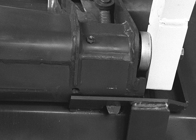
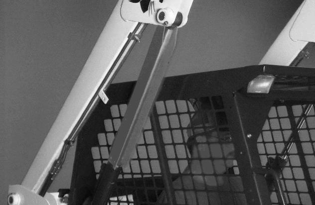
Figure PM-2
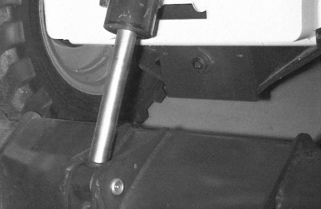
Maintenance and service work can be done with the lift arms lowered. If the lift arms are raised for service, use the following procedure:
Put jackstands under the rear corners of the loader frame (Inset) [Figure PM-1]

Remove any attachment before raising the lift arms.
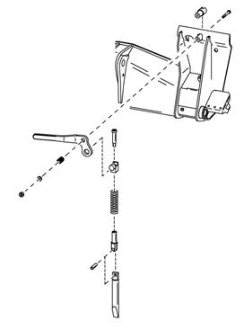
Disconnect the spring from the lift arm support device retaining pin (Item 1) [Figure PM-1]. Hold onto the lift arm support device (Item 2) [Figure PM-1] and remove the retaining pin.
Lower the lift arm support device to the top of the lift cylinder. Fasten the free end of the spring (Item 1) [Figure PM-2] to the lift arms support device so there will be no interference with the support device engagement.
With the operator in the seat, seat belt fastened and seat bar lowered, start the engine, press the green PRESS TO OPERATE Button.
Raise the lift arms, until the lift arm support device drops onto the lift cylinder rod (Item 1) [Figure PM-3]
Lower the lift arms slowly until the support device is held between the lift arm and the lift cylinder. Stop the engine. Raise the seat bar and mo ve foot pedals (or hand controls) until both lock.
LIFT ARM SUPPORT DEVICE (CONT’D)
Engaging The Lift Arm Support Device (Cont’d)
Figure PM-4
Install pin (Item 1) [Figure PM-4] into the rear of the lift arm support device below the cylinder rod.
Disengaging The Lift Arm Support Device
Figure PM-5
Remove the pin from the lift arm support device.
Connect the spring (Item 1) [Figure PM-5] from the lift arm support device to the bracket below the lift arms.
With the operator in the seat , seat belt fastened and seat bar lowered, start the engi ne, press the green PRESS TO OPERATE Button.
Raise the lift arms a small amount and the spring will lift the support device off the lift cylinder rod.
Lower the lift arms and stop the engine.
Raise the seat bar and move pedals until both lock.

Disconnect the spring from the bracket.
Figure PM-6
Raise the support device into storage position and insert pin (Item 1) [Figure PM-6] through lift arm support device and bracket.
Connect spring to pin.
OPERATOR CAB Description
The Bobcat loader has an operator cab (ROPS and FOPS) as standard equipment to protect the operator from rollover and falling objects. Check with your dealer if the operator cab has been damaged. The seat belt must be worn for rollover protection.
ROPS / FOPS - Roll Over protective Structure per SAE J1040 and ISO 3471, and Falling Object Protective Structure per SAE J1043 and ISO 3449, Level I.
Level I - Protection from falling bricks, small concrete blocks, and hand tools enco untered in operations such as highway maintenance, landscaping, and other construction sites services.
Level II - Protection from falling trees, rocks; for machines involved in site clearing, overhead demolition or forestry.
Warning
Never modify operator cab by welding, grinding, drilling holes or adding attachments unless instructed to do so by Bobcat. Changes to the cab can cause loss of operator protection from rollover and falling objects, and result in injury or death.
W-2069-1299
Warning
Before the cab or the lift arms are raised for service, jackstands must be put under the rear corners of the frame. Failure to use jackstands can allow the machine to tip backward causing injury or death.
W-2014-0895
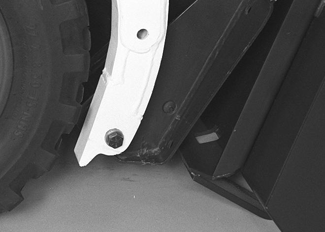
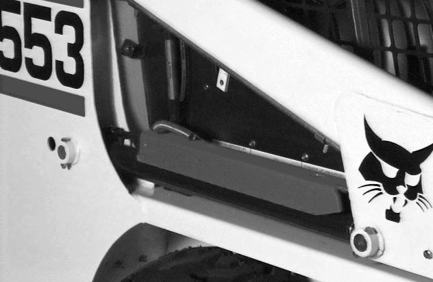
Raising The Operator Cab
Figure PM-7
Stop the loader on a level surf ace. Lower the lift arms. Stop the engine. If the lift arms must be up while raising the operator cab, install the lift arm support device. (See LIFT ARM SUPPORT DEVICE on Page PM-6).
Put jackstands under the rear corners of loader (Inset) [Figure PM-7]
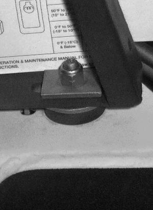
Figure PM-8
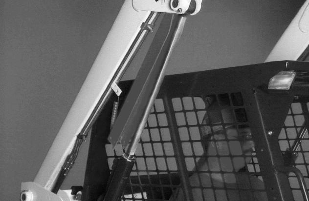
Loosen the nut (both sides) at the corner of the operator cab [Figure PM-8]
Remove the nut and plate (both sides) [Figure PM-8]
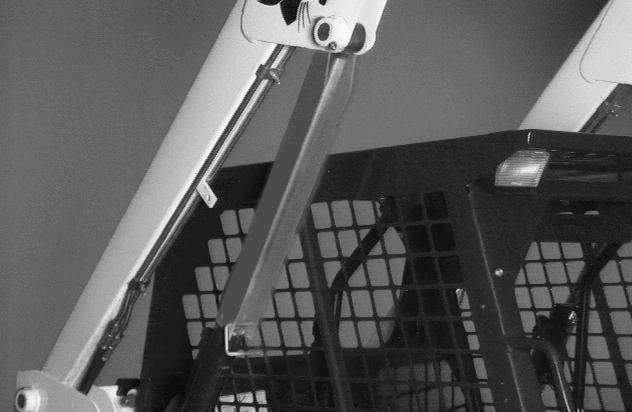
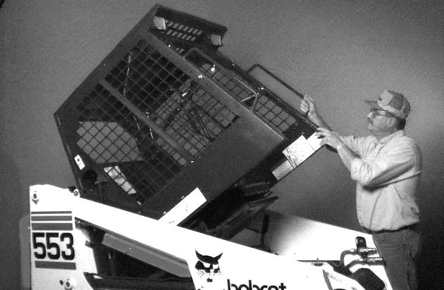
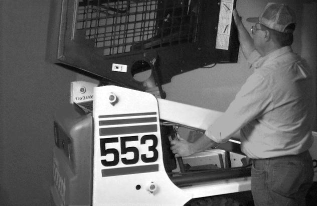
Lift on the grab handle and bottom of the operator cab slowly until the cab latching mechanism engages and the cab is all the way up [Figure PM-7]
OPERATOR CAB (CONT’D)
Lowering The Operator Cab WARNING
Both sets of fasteners at the front of the operator cab (ROPS) must be assembled as shown in this manual. Failure to secure ROPS correctly can cause injury or death.
Emergency Exit
The front opening on the operator cab and rear window provide exits.
Rear Window: (If Equipped)
Pull down on the bottom of the operator cab until it stops at the latching mechanism. Release the latching mechanism [Figure PM-9] and pull the cab all the way down.
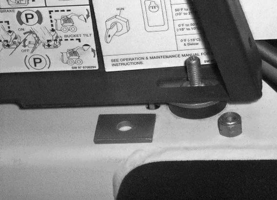
Install the plate and nut (both sides) [Figure PM-8]
Tighten the nuts [Figure PM-8] to 40-50 ft.-lbs. (54-68 Nm) torque.
Pull on the tag on the top of the rear window to remove the rubber cord [Figure PM-10]
Push the rear window out of the rear of the operator cab.

OPERATOR CAB (CONT’D)
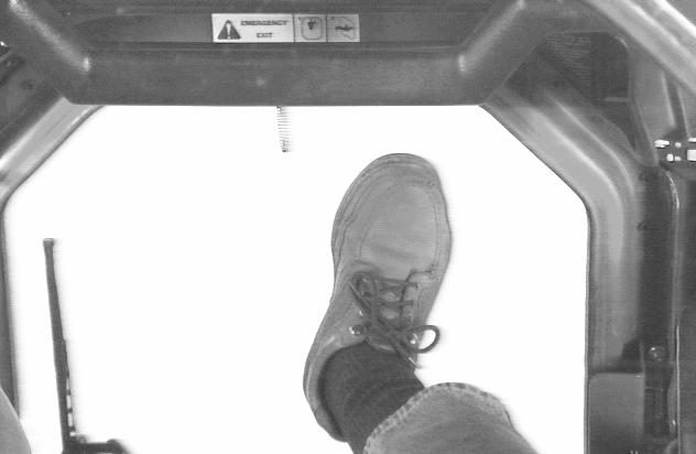
Front Door (If Equipped)
Figure PM-12
P9216
NOTE: When an Operator Cab Enclosure Kit is installed, the window of the front door can be used as an emergency exit [Figure PM-12].
Pull the plastic loop at the to p of the window in the front door to remove the rubber cord [Figure PM-12].
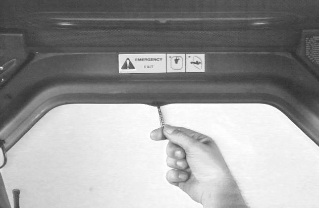
Figure PM-13
P9217
Push the window out with your foot [Figure PM-13].
Exit through the front door.
Seat Bar Restraint System
The seat bar restraint system has a pivoting seat bar with arm rests and spring loaded interlocks for the lift and tilt control pedals.
The operator controls the use of the seat bar. The seat bar in the down position helps to keep the operator in the seat.
The interlocks require the ope rator to lower the seat bar in order to operate the foot pedal controls.
When the seat bar is up, the lift and tilt control pedals are locked when returned to the NEUTRAL position.
Warning
Avoid Injury Or Death
The seat bar system must lock the lift and tilt control pedals in neutral when the sear bar is up. Service the system if pedals do not lock correctly.
W-2105-1285
Inspecting The Seat Bar
Sit in the seat and fasten the seat belt. Engage the parking brake. Pull the seat bar all the way down. Start the engine. Press the green PRESS TO OPERATE Button. Operate each foot pedal to check that both the lift and tilt functions operate correctly. Raise the lift arms until the attachment is about 2 feet (600 mm) off the ground.
Raise the seat bar. Try to move each foot pedal. Pedals must be firmly locked in th e NEUTRAL position. There must be no motion of the lift arms or tilt (bucket) when the pedals are pushed.
Pull the seat bar down, press the PRESS TO OPERATE Button and lower the lift arms. Operate the lift pedal. While the lift arms are going up, raise the seat bar. The lift arms must stop.
Lower the seat bar, press the green PRESS TO OPERATE Button, lower the lift arms and put the attachment flat on the ground. Stop the engine. Raise the seat bar and operate the foot pedals to be sure that the pedals are firmly locked in the NEUTRAL position. Unbuckle the seat belt.
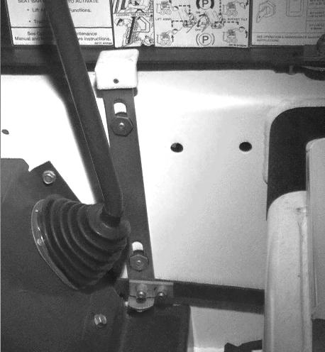
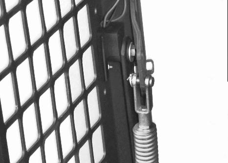
Maintaining The Seat Bar
(See SERVICE SCHEDULE on Page PM-5) and on the loader for correct service interval.
Both Sides of Loader
P10361
Both Sides of Loader
P10717
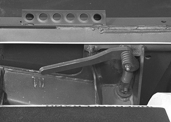
Clean any debris or dirt from the moving parts [Figure PM-14] & [Figure PM-15]
Inspect the linkage bolts and nuts for tightness. The correct torque is 25-28 ft.-lbs. (34-38 Nm).
If the seat bar system does not function correctly, check for free movement of each linkage part. Check for excessive wear. Adjust pedal control linkage. Replace parts that are worn or damaged. Use only genuine Bobcat replacement parts.
BOBCAT INTERLOCK CONTROL SYSTEM (BICS™)
Inspecting The BICS Controller (Engine StoppedKey ON)
Figure PM-16
1.Sit in operator’s seat. Turn key ON, lower the seat bar and disengage parking brake. Press the green PRESS TO OPERATE Button. All five BICS controller lights should be ON (Items 1, 2, 3, 4 & 5)[Figure PM16].
2.Engage the parking brake and raise the seat bar fully. System Activated (Item 1), Seat Bar (Item 2), Valve (Item 3) and Traction lights (Item 4) [Figure PM-16] should be OFF.
NOTE: Record what lights are flashing (if any) and the number of light flashes. (See Troubleshooting Chart Page SA-5.)
3.Exit the loader and press Traction Lock Override button. Traction light (Item 4) [Figure PM-16] should be ON. Press override button again and Traction light (Item 4) [Figure PM-16] should be OFF.
Inspecting The Seat Bar Sensor (Engine RUNNING)
4.Sit in operator’s seat, lower seat bar, engage parking brake and fasten seat belt.

5.Start engine and operate at low idle. Press the green PRESS TO OPERATE Button. While raising the lift arms, raise the seat bar fully. The lift arms should stop. Repeat using the tilt function.
NOTE: The auxiliary hydraulic functions are not affected by the Bobcat Interlock Control System (BICS™).
Inspecting The Traction Lock (Engine RUNNING)
6.Fasten seat belt, disengage parking brake, press the green PRESS TO OPERATE Button and raise seat bar fully. Move steering levers slowly forward and backward. The TRACTION lock should be engaged. Lower the seat bar. Press the green PRESS TO OPERATE Button.
7.Engage parking brake and move steering levers slowly forward and backward. The TRACTION lock should be engaged.
Inspecting The Lift Arm By-Pass Control
8.Raise the lift arms 6 feet (2 meters) off the ground. Stop the engine.
Pull up and hold the lift arm by-pass control knob, then press the toe of the lift arm pedal until the lift arms slowly lower.
Warning
AVOID INJURY OR DEATH
The Bobcat Interlock Control System (BICS™) must deactivate the lift, tilt and traction drive functions. If it does not, contact your dealer for service. DO NOT modify the system.
W-2151-0394
Opening And Closing The Rear Door
Warning
Avoid Injury Or Death
Never service or adjust the machine when the engine is running unless instructed to do so in the manual.
Warning
Keep the rear door closed when operating the machine. Failure to do so could seriously injure a bystander.
Adjusting The Rear Door
Reach into the slot in the rear door and pull the latch handle (Item 1) [Figure PM-17]
Pull the rear door open.
Move the door stop into the engaged position (Item 2) [Figure PM-17] to hold the door open.
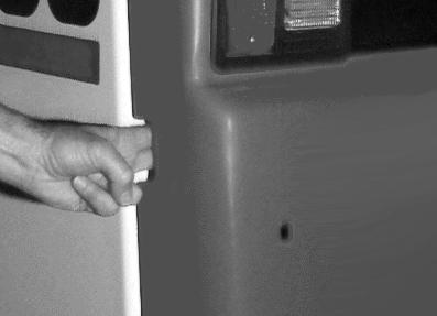
Move the door stop up (Item 3) [Figure PM-17] to disengage the door stop and allow the door to close.
Close the door
The door latch catch (Item 1) [Figure PM-18] can be adjusted side to side for alignment with the door latch mechanism.
Close the rear door before operating the loader.
Rear Grill
Figure PM-19
To remove the rear grill, remove the four grill mounting bolts (Item 1) [Figure PM-19]
Lift the rear grill up and remove from the loader.
Air Cleaner Service
Replacing Filter Elements
Figure PM-20
See SERVICE SCHEDULE on Page PM-5 for the interval to service the air cleaner.
Check the air intake hose for damage. Check the air cleaner housing for damage. Check to make sure all connections are tight.
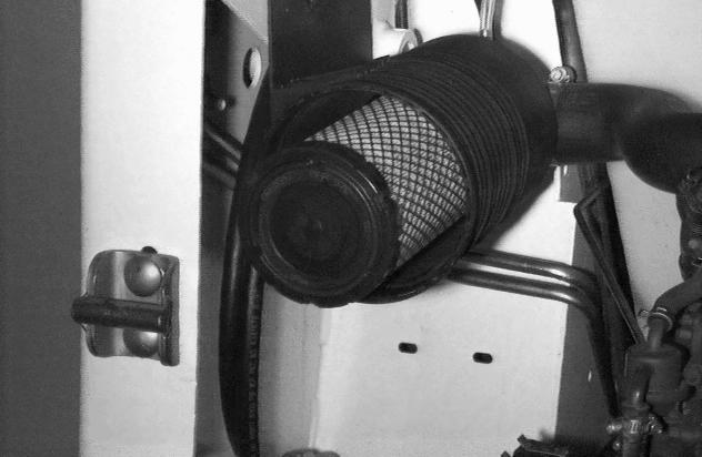
Replace the outer filter element only when the red ring (Item 1) [Figure PM-20] shows in the window of the condition indicator.
NOTE:Push the button on the condition indicator (Inset) [Figure PM-20] and start the engine. If the red ring does not show, do not replace the filter element [Figure PM-21].
Disengage the clamps (Item 1) and remove the dust cover (Item 2) [Figure PM-20].
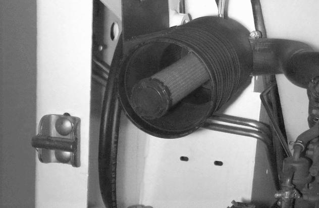
Outer Element: Pull the outer filter element from the air cleaner housing [Figure PM-21].
NOTE:Make sure all sealing surfaces are free of dirt and debris.
Install a new outer element.
Install the dust cover and fasten the clamps.
Inner Element: Only replace the inner filter element under the following conditions:
•Replace the inner filter element every third time the outer filter is replaced.
•Replace the inner filter element when the red ring still shows in the condition in dicator window after the outer filter is replaced.
AIR CLEANER SERVICE (CONT’D)
Replacing Filter Elements (Cont’d)
Figure PM-22
Fuel System
Fuel Specifications
Use only clean, high quality diesel fuel, Grade No. 2 or Grade No. 1.
The following is one suggeste d blending guideline which should prevent fuel gelling during cold temperatures:
We recommend an operator contact their fuel supplier for local recommendations.
Filling The Fuel Tank
Pull the inner filter element from the air cleaner housing [Figure PM-22]
NOTE:Make sure all sealing surfaces are free of dirt and debris.
Install the new inner element.
Record the operating hours of the loader on the decal inside the rear door.
Warning
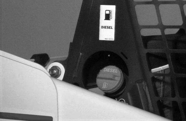
Stop and cool the engine before adding fuel. NO SMOKING! Failure to obey warnings can cause an explosion or fire.
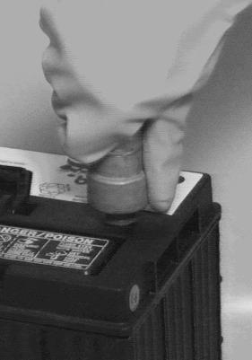
Remove the fuel fill cap [Figure PM-23]
Use a clean, approved safety co ntainer to add fuel of the correct specifications. Add fuel only in an area that has free movement of air and no open flames or sparks. NO SMOKING!
Install and tighten the fuel fill cap [Figure PM-23]
FUEL SYSTEM (CONT’D)
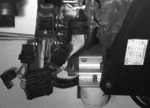
Fuel Filter
Warning
Always clean up spilled fuel or oil. Keep heat, flames, sparks or lighted tobacco away from fuel and oil. Failure to use care around combustibles can cause explosion or fire which can result in injury or death.
W-2103-1285
Remove Water:
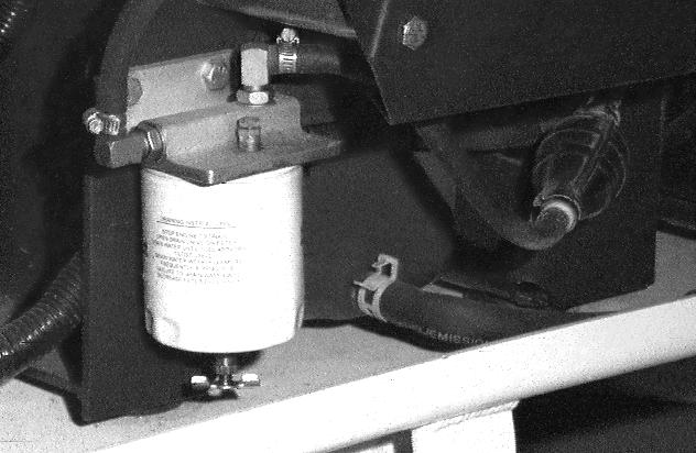
Early Models: Shut-off the fuel supply (Item 1) [Figure PM-24] (turn clockwise).
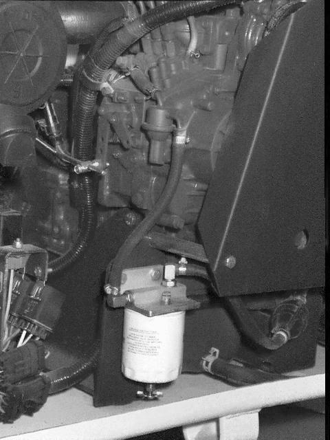
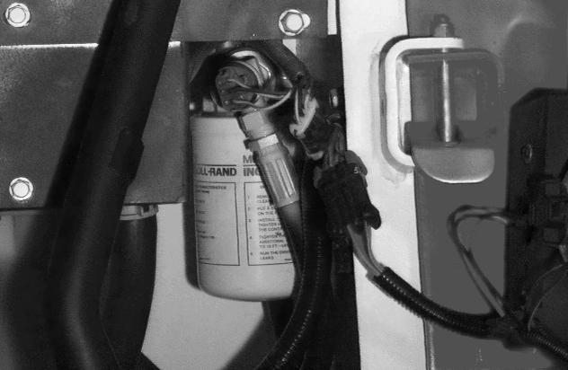
See the (SERVICE SCHEDULE on Page PM-5) for the service interval when to remove the water from the fuel filter and to replace the fuel filter.
Loosen the drain at the bottom of the filter element (Item 1) [Figure PM-25] to drain the water from filter.
Open the shut-off valve [Figure PM-24]
Replacing Filter:
Clean area around the fuel filter.
Close the shut-off valve (Item 1) [Figure PM-24]
Remove the fuel filter element (Item 2) [Figure PM-25]
Install the new filter element.
Tighten the fuel filter.
Open the shut-off valve [Figure PM-24]
FUEL SYSTEM (CONT’D)
Removing Air From The Fuel System
Figure PM-26
Warning
Always clean up spilled fuel or oil. Keep heat, flames, sparks or lighted tobacco away from fuel and oil. Failure to use care around combustibles can cause explosion or fire which can result in injury or death.
W-2103-1285
After replacing the filter element or when the fuel tank has run out of fuel, air must be removed from the fuel system before starting the engine.
Be sure the engine is cool.
Open the rear door.
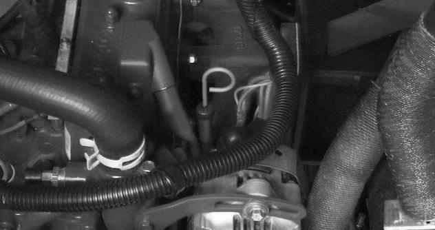
Open the vent plug (Item 1) [Figure PM-26] on top of the fuel filter head.
Operate the hand pump (Item 2) [Figure PM-26] until fuel flows from the vent plug with no air bubbles.
Tighten the vent plug.
Operate the hand pump (Item 2) [Figure PM-26] until it feels solid.
Move the engine speed control to minimum RPM. Open the valve (Item 3) [Figure PM-26] and squeeze the hand pump several times.
Start the engine.
When the engine runs smoothly, close the valve (Item 3) [Figure PM-26]
Close the rear door.
Engine Lubrication System
Checking Engine Oil
Check the engine oil level ever y day before starting the engine for the work shift.
Figure PM-27
Park the machine on level ground. Open the rear door and remove the dipstick (Item 1) [Figure PM-27]
Keep the oil level between the marks on the dipstick. Do not overfill.
Oil Chart
Figure PM-28
Use good quality motor oil that meets API Service Classification of CD or better (See Oil Chart [Figure PM28]).
Install the dipstick and close the rear door.
ENGINE LUBRICATION SYSTEM (CONT’D)
Replacing The Oil And Filter
Figure PM-29
Follow the service interval for replacing the engine oil and filter(See SERVICE SCHEDULE on Page PM-5).
Run the engine until it is at operating temperature. Stop the engine.
Open the rear door.
Remove the cap (Item 1) [Figure PM-29], from the end of the hose and drain the oil into a container. Dispose of used oil in an environmentally safe manner.
Remove the filter (Item 2) [Figure PM-29]
Clean the filter housing surface.

Put clean oil on the gasket of the new filter. Install the filter and hand tighten.
Install the cap on the drain hose.
Remove the oil fill cap (Item 1) [Figure PM-30]
Use a good quality motor oil that meets API Service Classification of CD or better (See Oil Chart on Page PM18).
Fill to capacity. (See Capacities on Page SPEC-5). Do not overfill.
Start the engine and let it run for about 5 minutes. Check for leaks at the filter. Check the oil level. Add oil until the level is at the FULL mark on the dipstick.
Install the oil fill cap (Item 1) [Figure PM-30]
NOTE:DO NOT overfill the crankcase.
Record the operating hours of the loader on the decal inside the rear door.
Close the rear door before operating the loader.
Engine Cooling System
Checking the cooling system every day to prevent overheating, loss of performance or engine damage.
Warning
Wear safety glasses to prevent eye injury when any of the following conditions exist:
•When fluids are under pressure.
•Flying debris or loose material is present.
•Engine is running.
•Tools are being used.
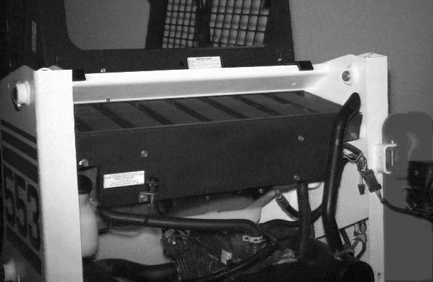
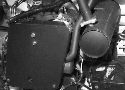
Cleaning The Cooling System
Figure PM-31
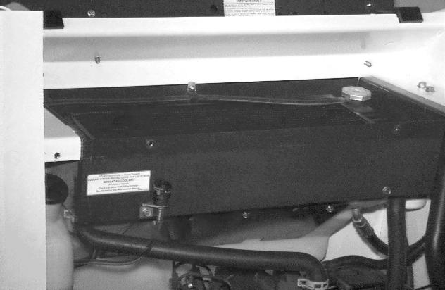
Open the rear door.
Remove the access panel from the blower housing (Item 1) [Figure PM-31].
Remove the rear grill. (See REAR GRILL on Page PM14).
Use air pressure or water pr essure to remove the debris in the area of the radiator and oil cooler [Figure
ENGINE COOLING SYSTEM (CONT’D)
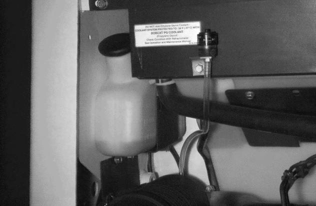
Checking The Coolant Level
Figure PM-33
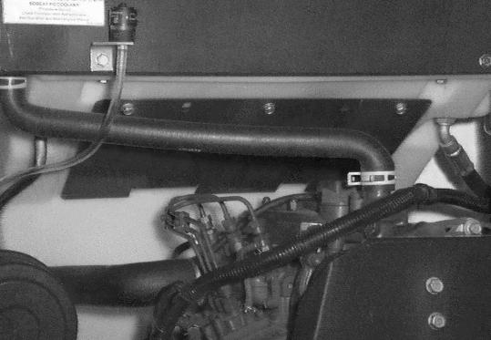
The coolant recovery tank (Item 1) [Figure PM-33] must be at the FULL COLD mark when engine is cold.
Propylene Glycol
NOTE: The loader is factory filled with propylene glycol coolant. DO NOT mix propylene glycol with ethylene glycol.
Add premixed coolant; 47% water 53% propylene glycol to the recovery tank if the coolant level is low.
One gallon and one pint of propylene glycol mixed with one gallon of water is the correct mixture of coolant to provide a -34°F (-37°C) freeze protection.
Use a refractometer to check the condition of Propylene glycol in your cooling system.
Close the rear door before operating the loader.
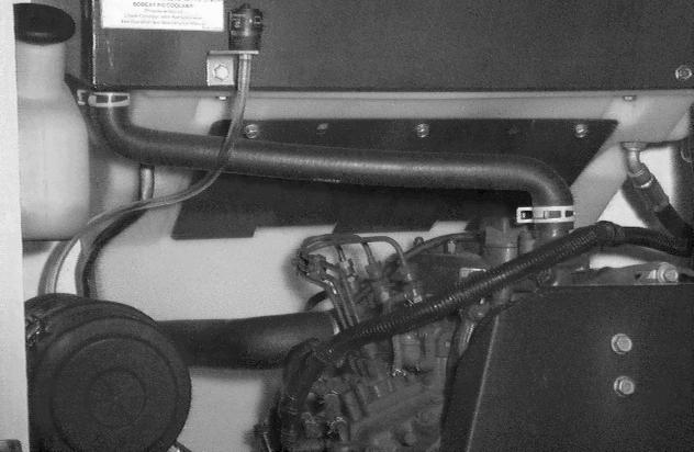
Replacing The Coolant
Figure PM-34
Remove the rear door. (See REAR GRILL on Page PM14).
Open the rear door.
Remove the radiator cap (Item 1) [Figure PM-34]
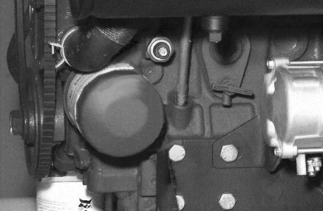
Figure PM-35
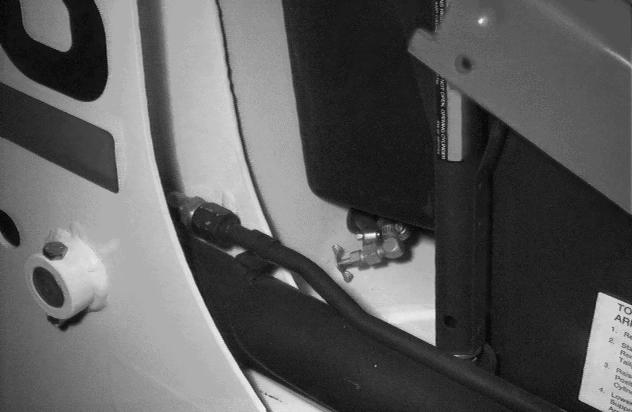
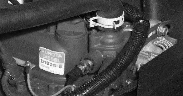
Connect a hose to the coolant drain valve (Item 1) [Figure PM-35] (located behind the engine oil filter) or use a funnel to keep coolant from getting into the engine compartment.
Open the valve and drain all the coolant into a container.
Close the valve.
Fill the radiator with premixed coolant and install the radiator cap. (See Checking The Coolant Level on Page PM-21) for premix recommendations.
ENGINE COOLING SYSTEM (CONT’D)
Replacing The Coolant (Cont’d)
Important
Avoid Engine Damage
Always use the correct ratio of water to antifreeze.
Too much antifreeze reduces cooling system efficiency and may cause serious premature engine damage.
Too little antifreeze reduces the additives which protect the internal engine components; reduces the boiling point and freeze protection of the system.
Always add a premixed solution. Adding full strength concentrated coolant can cause serious premature engine damage.
I-2124-0497
Alternator Belt
Adjusting The Alternator Belt
Figure PM-37
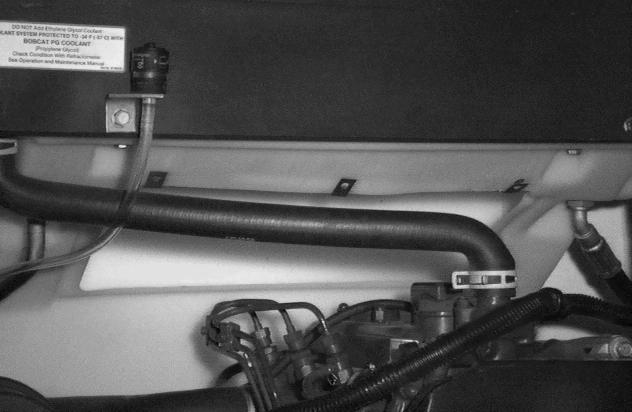
Fill the coolant recovery tank 1/3 full with premixed coolant (Item 1) [Figure PM-36].
Check the radiator cap for correct pressure rating or overheating can result.
Check for leaks in the coolin g system. Check for worn or damaged hoses, clamps or radiator. Check for loose or worn water pump belt.
Replace damaged parts immediately to prevent leaks and overheating.
Install the radiator cap and the rear grill and close the rear door
Stop the engine and open the rear door.
Remove the engine belt shield.
Loosen the mounting bolt (Item 1) and adjustment bolt (Item 2) [Figure PM-37].
Move the alternator to set the belt tension at 5/16'' (8 mm) movement between pulleys with 15 pounds (67 N) of force [Figure PM-38]
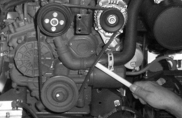
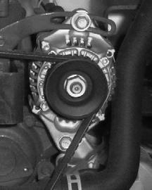
Tighten the adjustment bolt and mounting bolt.
Close the rear door.
Install the engine belt shield.
ELECTRICAL SYSTEM Description
The loader has a 12 volt, negative ground alternator charging system. The electrical system is protected by fuses and relays. The fuses will protect the electrical system when there is an electrical overload. Find the reason for the overload before starting the engine again.
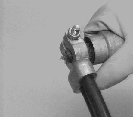
Electrical System Maintenance
Fuse Location
The battery cables must be clean and tight. Remove acid or corrosion from the battery and cables with a baking soda and water solution [Figure PM-39]
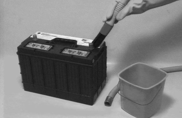
Cover the terminals of the battery with Bobcat Battery Saver (P/N 886398) to prevent corrosion. Do not use silicone based products.
Install the terminal covers.
ELECTRICAL SYSTEM (CONT’D)
Using A Booster Battery (Jump Starting)
Important
Damage to the alternator can occur if: Engine is operated with battery cables disconnected. Battery cables are connected when using a fast charger or when welding on the loader. (Remove both cables from the battery.)
Extra battery cables (booster cables) are connected wrong.
I-2023-1285
Warning
Batteries contain acid which burns eyes and skin on contact. Wear goggles, protective clothing and rubber gloves to keep acid off body.
In case of acid contact, wash immediately with water. In case of eye contact get prompt medical attention and wash eye with clean, cool water for at least 15 minutes.
If electrolyte is taken internally drink large quantities of water or milk! DO NOT induce vomiting. Get prompt medical attention.
W-2065-1296
Warning
Keep arcs, sparks flames and lighted tobacco away from batteries. When jumping from booster battery make final connection (negative) at engine frame.
Do not jump start or charge a frozen or damaged battery. Warm battery to 60°F (16°C) before connecting to a charger. Unplug charger before connecting or disconnecting cables to battery. Never lean over battery while boosting, testing or charging.
Battery gas can explode and cause serious injury.
W-2066-1296
If it is necessary to use a booster battery to start the engine, BE CAREFUL! There must be one person in the operator’s seat and one person to connect and disconnect the battery cables.
The key switch must be OFF. The booster battery must be 12 volt.
Connect the end of the first c able to the positive terminal (+) of the booster battery (Item 1) [Figure PM-41]
Connect the other end of t he same cable to the loader battery positive (+) terminal (Item 2) [Figure PM-41].

Connect the end of the second cable to the negative terminal (-) of the booster battery (Item 3) [Figure PM41]. Connect the other end of second cable to the engine ground (Item 4) [Figure PM-41]
Keep cables away from moving parts. Start the engine.
After the engine has started, remove the ground cable connected to the engine first.
Remove the cable connected to the loader battery.
ELECTRICAL SYSTEM (CONT’D)
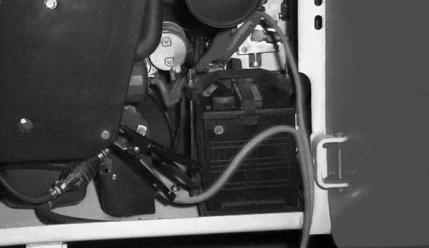
Removing And Installing The Battery
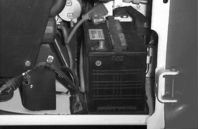
Warning
Batteries contain acid which burns eyes and skin on contact. Wear goggles, protective clothing and rubber gloves to keep acid off body.
In case of acid contact, wash immediately with water. In case of eye contact get prompt medical attention and wash eye with clean, cool water for at least 15 minutes.
If electrolyte is taken internally drink large quantities of water or milk! DO NOT induce vomiting. Get prompt medical attention. W-2065-1296
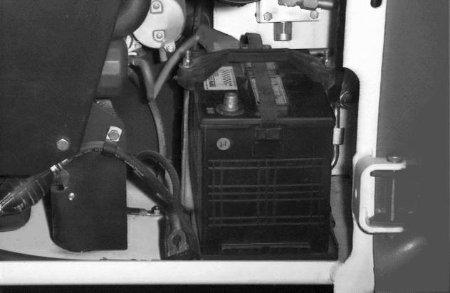
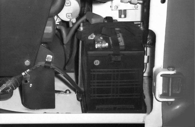
ELECTRICAL SYSTEM (CONT’D)
Removing And Installing The Battery (Cont’d)
Figure PM-45
Always clean the battery terminals and cable ends when installing a new or used battery [Figure PM-45]
Do not touch any metal parts with the battery terminals.
Connect and tighten the batt ery cables. Connect the negative (-) cable last to prevent sparks.
Inspect the battery holddown to be sure that it is in good condition. If it is cracked or broken, replace it.
Close the rear door.
HYDRAULIC / HYDROSTATIC SYSTEM
The hydraulic and hydrostatic systems use the same hydraulic fluid reservoir.

The system has an engine driven pump that supplies fluid to the control valve, lift and tilt cylinders.
Fluid also goes from the cont rol valve to the hydrostatic transmission pumps to provide charge pressure and cooling.
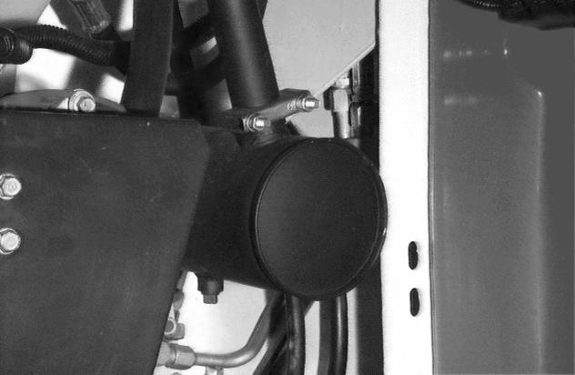
A filter is installed on the right side of the engine compartment. This filter cleans the fluid for the hydrostatic transmission.
The oil cooler is under the r adiator. The oil cooler cools the hydraulic fluid before it returns to the hydrostatic pump.
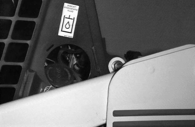
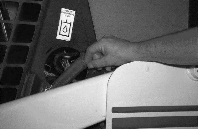
Remove the filler cap (Item 1) [Figure PM-47].
Add fluid to the reservoir unt il it shows in the sight gauge [Figure PM-46]
Install the filler cap (Item 1) [Figure PM-47].
Use only recommended fluid in the hydraulic system. (See Hydraulic System on Page SPEC-5).
Put the loader on a level surface
Lower the lift arms and tilt the Bob-Tach fully back. Stop the engine.
Hydraulic fluid must show in the sight gauge (Item 1) [Figure PM-46]
HYDRAULIC/HYDROSTATIC SYSTEM (CONT’D)
Replacing Hydraulic/Hydrostatic Filter
Figure PM-48
(See SERVICE SCHEDULE on Page PM-5) for the correct service interval to replace the filter.
Stop the engine. Open the rear door.
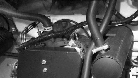
Clean the area around the filt er housing and remove the filter element (Item 1) [Figure PM-48]
Clean the surface where the filter seal contacts the filter housing.
Lubricate the rubber gasket with grease. Install the filter element and hand tighten.
Operate the loader and check for leaks at the filter.
Check fluid level in the reservoir and add as needed.
Close the rear door.
Warning
Always clean up spilled fuel or oil. Keep heat, flames, sparks or lighted tobacco away from fuel and oil. Failure to use care around combustibles can cause explosion or fire which can result in injury or death. W-2103-1285
Replacing Hydraulic Fluid
Figure PM-49
(See SERVICE SCHEDULE on Page PM-5) for the service interval to replace the fluid. Replace the fluid if it becomes contaminated and after any major repairs.
Remove the filler cap (Item 1) [Figure PM-49].
Figure PM-50
Remove the screen (Item 1) [Figure PM-50]
Wash the screen in clean solvent. Install the screen in the fill pipe.
Remove the hose and remove the fluid from the hydraulic reservoir.
Remove the filter element. Install a new filter element (See Replacing Hydraulic/Hydrostatic Filter, Page PM28.)
Add hydraulic/hydrostatic fluid to the reservoir. (See LOADER SPECIFICATIONS on Page SPEC-3) DO NOT fill above the sight glass.
Install the filler cap. Operate the loader. Stop the engine. Check the fluid level and add as needed.
Warning
Stop engine and allow the muffler to cool before cleaning the spark chamber. Wear safety goggles. Failure to obey can cause serious injury.
W-2011-1285
Warning
When an engine is running in an enclosed area, fresh air must be added to avoid concentration of exhaust fumes. If the engine is stationary, vent the exhaust outside. Exhaust fumes contain odorless, invisible gases which can kill without warning.
W-2050-1285
Have a second person (wearing safety goggles) hold a block of wood over the outlet of the muffler (with the engine running) for about 10 seconds.
Stop the engine and install the plug.
Close the rear door.
Warning
Never use machine in atmosphere with explosive dust or gases or where exhaust can contact flammable material. Failure to obey warnings can cause injury or death.
W-2068-1285
Important
This loader is factory equipped with a U.S.D.A. Forestry Service approved spark arrestor muffler. It is necessary to do maintenance on this spark arrestor muffler to keep it in working condition. The spark arrestor muffler must be serviced by dumping the spark chamber every 100 hours of operation.
If this machine is operated on flammable forest, brush or grass covered land, it must be equipped with a spark arrestor attached to the exhaust system and maintained in working order. Failure to do so will be in violation of California State Law, Section 4442 PRC.
Make reference to local laws and regulations for spark arrestor requirements.
I-2022-0595
(See SERVICE SCHEDULE on Page PM-5) for correct service interval to clean the spark arrestor muffler.
Do not operate the loader with a defective exhaust system.
Stop the engine. Open the rear door.
Cover the battery with a fire retardant material.
Remove the plug (Item 1) [Figure PM-51] at the bottom of the muffler.
Start the engine.
Tire Maintenance
Wheel Nuts
Figure PM-52
(See SERVICE SCHEDULE on Page PM-5) for the service interval to check the wheel nuts.
When installing wheel nuts, tighten to 160 ft.-lbs. (217 N•m) torque.
When checking wheel nut torque, set the torque wrench to 140 ft.-lbs. (190 N•m) to prevent over-tightening.
Tire Rotation
Check the tires regularly for wear, damage and pressure. (See LOADER SPECIFICATIONS on Page SPEC-3) for the correct tire pressure.
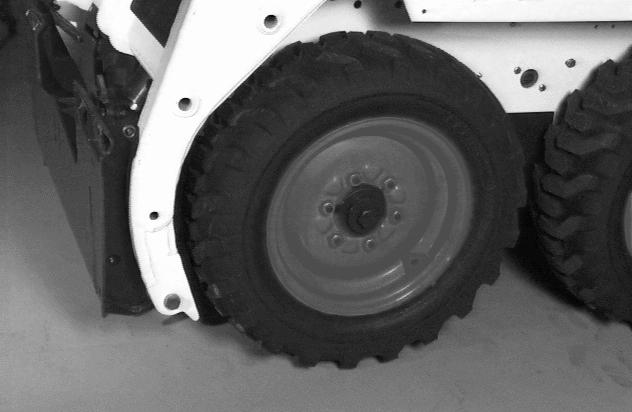
Figure PM-53
Rear tires usually wear faster than front tires. To keep tire wear even, move the front tires to the rear and rear tires to the front [Figure PM-53]
It is important to keep the same size tires on each side of the loader. If different sizes are used, each tire will be turning at a different rate and cause excessive wear. The tread bars of all the tires must face the same direction.
Recommended tire pressure must be maintained to avoid excessive tire wear and loss of stability and handling capability. Check for correct pressure before operating the loader.
Tire Mounting
Tires are to be repaired only by an authorized person using the proper procedures and safe equipment. Tires and rims must always be ch ecked for correct size before mounting. Check rim and tire bead for damage.
The rim flange must be cleaned and free of rust. The tire bead and rim flange must be lubricated with a rubber lubricant before mounting the tire, void excessive pressure which can rupture the tire and cause serious injury or death. During inflation of the tire, check the tire pressure frequently to avoid over inflation.
Inflate tires to the MAXIMUM pressure shown on the side wall of the tire. DO NOT mix brands of tires used on the same loader.
Warning
Do not inflate tires above specified pressure. Failure to use correct tire mounting procedure can cause an explosion which can result in injury or death.
W-2078-1285
FINAL DRIVE TRANSMISSION (CHAINCASE)
Checking And Adding Oil
The chaincase contains the final drive sprockets and chains and uses the same type of oil as the hydraulic / hydrostatic system (See LOADER SPECIFICATIONS on Page SPEC-3).
Drive the loader onto a level surface and stop the engine.
If oil can be reached with the tip of your finger through the hole, the oil level is correct.
If the level is low, add oil through the check plug hole until the oil flows from the hole.
Install
Lubricating The Bobcat Loader
Lubrication Locations
Lubricate the loader as specified for the best performance of the loader (See SERVICE SCHEDULE on Page PM-5).
Record the operating hours ea ch time you lubricate the Bobcat loader.
Always use a good quality lithium based multi-purpose grease when you lubricate the loader. Apply until extra grease shows.
Lower the lift arms all the way and tilt the Bob-Tach all the way forward until it is on the ground.
Lubricate the following locations on the loader:
LUBRICATING THE BOBCAT LOADER (CONT’D)
Lubrication Locations (Cont’d)
Figure PM-59
5.Rod End Tilt Cylinder [Figure PM-59]
6.Bob-Tach Pivot Pin (Both Sides) [Figure PM-59]
7.Bob-Tach Wedge (Both Sides) [Figure PM-59].
Figure PM-60
8.100 Hours: Steering Lever Shaft Bearings (2) [Figure PM-60] (The opposite end is lubricated under the cab.).
Put oil in the hole of the cross shaft where the right and left steering shafts meet under the cab.
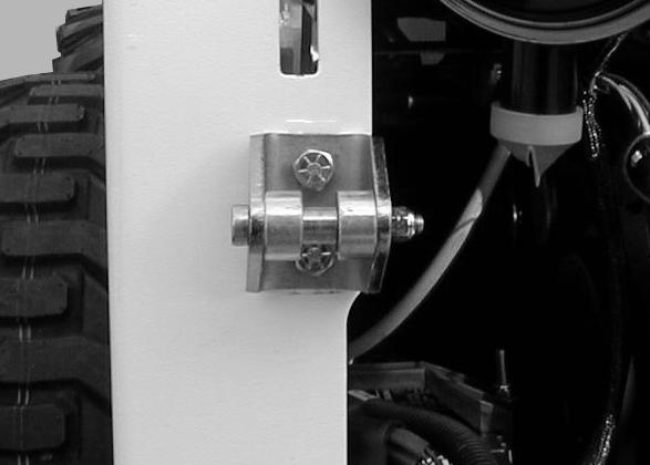
Pivot Pins
Inspection And Maintenance
Figure PM-61
All lift arm and cylinder pivots have a large pin held in position with a retainer bolt and lock nut (Item 1) [Figure PM-61]
Check that the lock nuts are tightened to 18-20 ft.lbs. (2427 Nm) torque.
Warning
Bob-Tach wedges must extend through the holes in attachment. Levers must be fully down and locked. Failure to secure wedges can allow attachment to come off and cause injury or death.
W-2102-0588
Wedge must contact lower edge of hole in the attachment.
The spring loaded wedge (Item 1) [Figure PM-62] must contact the lower edge of the hole in the attachment (Item 1) [Figure PM-63] and [Figure PM-64]
If the wedge does not contact the lower edge of the hole, the attachment will be loose and can come off the BobTach.
Move the Bob-Tach levers to engage the wedges [Figure PM-62]. The levers and wedges must move freely.
The wedges must extend through the holes in the attachment mounting frame (Item 1) [Figure PM-62]
Inspect the mounting frame on the attachment and BobTach, linkages and wedges for excessive wear or damage [Figure PM-65]. Replace any parts that are damaged, bent or missing. Keep all fasteners tight.
Look for cracked welds. Cont act your Bobcat dealer for repair or replacement parts.
Lubricate the wedges (See SERVICE SCHEDULE on Page PM-5) and (See LUBRICATING THE BOBCAT LOADER on Page PM-32).