16 minute read
OPERATOR SAFETY WARNINGS


Warning
Operator must have instructions before running the machine. Untrained operators can cause injury or death.
W-2001-1285
Safety Alert Symbol:This symbol with a warning statement, means: “Warning, be alert! Your safety is involved!” Carefully read the message that follows.
Never use the loader without instructions. See machine signs (decals), Operation & Maintenance Manual, and Operator’s Handbook.
Always use the seat bar and fasten seat belt snugly. Always keep feet on the foot pedals or footrests when operating loader.
Never use loader without operator cab with ROPS and FOPS approval. Fasten your seat belt.
Never use loader as man lift or elevating device for personnel.
Do not use loader in atmosphere with explosive dust, explosive gas, or where exhaust can contact flammable material.
Never carry riders. Keep bystanders away from work area.
Always carry bucket or attachments as low as possible. Do not travel or turn with lift arms up. Load, unload, and turn on flat level ground.
Never exceed Rated Operating Capacity.
Never leave loader with engine running or with lift arms up. To park, engage parking brake and put attachment flat on the ground.
Safety Equipment
Never modify equipment. Use only attachments approved by Bobcat® Company for this model loader.
The Bobcat loader must be equipped with safety items necessary for each job. Ask your dealer for information on the safe use of attachments and accessories.
1.SEAT BELT: Check belt fasteners and check for damaged webbing or buckle.
2.SEAT BAR: When up, it must lock the loader controls.
3.OPERATOR CAB (ROPS and FOPS): It must be on the loader with all fasteners tight.
4.HANDBOOK: Must be in the cab.
5.SAFETY SIGNS (DECALS): Replace if damaged.
6.SAFETY TREADS: Replace if damaged.
7.GRAB HANDLES: Replace if damaged.
8.LIFT ARM SUPPORT DEVICE: Replace if damaged.
9.PARKING BRAKE
10. BOBCAT INTERLOCK CONTROL SYSTEM (BICS™)

REFERENCE INFORMATION
Write the correct information for YOUR Bo bcat Loader in the spaces below. Always use these numbers when referring to your Bobcat loader.
NOTES:
YOUR BOBCAT® DEALER:
ADDRESS:
PHONE:
Bobcat Company
P.O. Box 128
Gwinner, ND 58040-0128
Foreword
This Operation & Maintenance Manual was writt en to give the owner/operator instructions on the safe operation and maintenance of the Bobcat Loader. READ AND UNDERSTAND THIS OPERATION & MAINTENANCE MANUAL BEFORE OPERATING YOUR Bobcat loader. If you have any questions, see your Bobcat dealer.
BOBCAT COMPANY IS ISO 9001:2000 CERTIFIED
ISO 9001:2000 is a set of international standards that control th e processes and procedures which we use to design, develop, manufacture, distribute, and service Bobcat products.
British Standards Institute (BSI) is the Certified Registrar Bobcat chose toassess the Company’s compliance with the ISO 9001:2000 set of standards. The BSI regi stration certifies that the two Bobc at manufacturing plants and the Bobcat corporate offices (Gwinner, Bismarck & West Fargo) in North Dakota are in compliance with ISO 9001:2000. Only certified assessors, like BSI, can grant registrations.
ISO 9001:2000 means that as a company we say what we do and do what we sa y. In other words, we have established procedures and policies, and we provide evidence that the procedures and policies are followed.
California Proposition 65 Warning
Diesel engine exhaust and some of its constituents are known to the State of California to cause cancer, birth defects and other reproductive harm.
Regular Maintenance Items
FLUID, Hydraulic/Hydrostatic
FUEL FILTER
AIR FILTER, Inner
HYDROSTATIC FILTER
Motor
- (2.5 gal.) 6903118 - (5 gal.)
RADIATOR CAP
6646678
PROPYLENE GLYCOL ANTI-FREEZE, Premixed [-34 F (-37C]
6724094
PROPYLENE GLYCOL ANTI-FREEZE, Concentrate
Serial Number Locations
Always use the serial number of the loader when requesting service information or when ordering parts. Early or later models (identification made by serial number) may use different parts, or it may be necessary to use a different procedure in doing a specific service operation.
Engine Serial Number

Delivery Report
Loader Serial Number
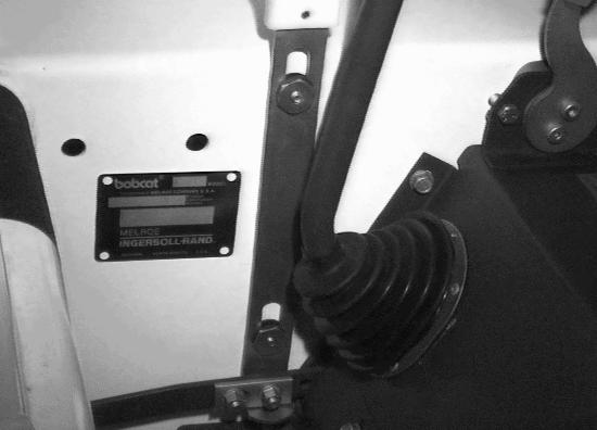
The loader serial number plate is located inside the operator cab on the loader frame [Figure 1]
Explanation of loader Serial Number:
Xxxx Xxxxx
The delivery report must be filled out by the dealer and signed by the owner or operator when the Bobcat loader is delivered. An explanation of the form must be given to the owner. Make sure it is filled out completely [Figure 3]
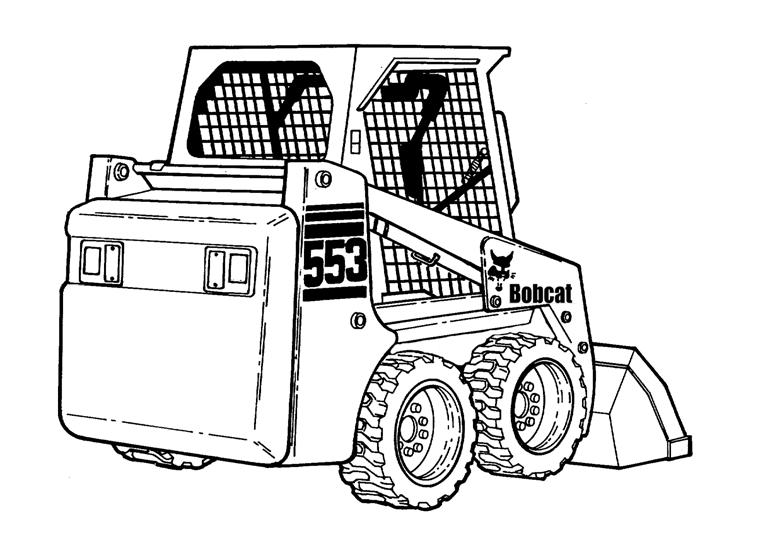
BOBCAT LOADER IDENTIFICATION
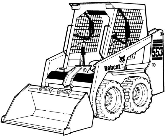
FRONT LIGHTS
OPERATOR SEAT WITH SEAT BELT
SEAT BAR
GRAB HANDLES
STEERING LEVER
BUCKET
TILT CYLINDER
BUCKET STEPS
UPRIGHTS
REAR GRILL
TAIL LIGHT
REAR WINDOW
SAFETY TREAD
LIFT CYLINDER
QUICK COUPLERS
OPERATOR CAB (ROPS & FOPS)
LIFT ARM
LIFT ARM SUPPORT DEVICE
REAR LIGHT
REAR DOOR
Options or Field Accessories - not standard equipment.
* TIRES
* TIRES - The Bobcat loader is factory equipped with standard tires. See Specifications Section and your Bobcat dealer for available tires.
† BUCKET - Several different buckets and other attachments are available from your Bobcat dealer.
● ROPS, FOPS - Roll Over Protective Structure, per SAE J1040 and ISO 3471, and Falling Object Protective Structure ISO 3449, Level I. Level II is available. The Bobcat loader is base-equipped with a standard operator cab as shown. Extra insulated cab is available as an option (Reduced noise level).
Features And Accessories
Standard Items
Model 553 Bobcat loaders are equipped with the following standard items:
•Adjustable Cushion Seat
•Auxiliary Hydraulics, Front
•Bob-Tach
•Bobcat Interlock Control System
•Instrumentation: Hourmeter, Engine Temperature and Fuel Gauges and Warning Lights
•Lift Arm Support Device
•Lights, Front & Rear
•Operator Cab (with ROPS / FOPS Approval)
•Parking Brake
•Rocker Switch Activated Glow Plugs
•Seat Bar
•Seat Belt
•Spark Arrestor Muffler
•Tires, 27 x 8.5-15 4PR (Machine Width-47 inches)
•Window, Rear
Options and Accessories
Below is a list of some equipment available form your Bobcat Loader dealer as Dealer and / or Factory Installed Accessories and Factory Installed Options. See your Bobcat dealer for other available options, accessories and attachments.
•Back-up Alarm & Horn
•Cab Enclosure
•Cab Heater Kit
•Catalytic Exhaust Purifier
•Coolant Level Sensor
•Cover Kit (Hydraulic Reservoir Area)
•Deluxe Cab
•Deluxe Cab w/Heater
•Engine Heater
•Hydraulic Bucket Positioning (Includes On/Off Selection)
•Fire Extinguisher
•Flasher Lights
•Falling Object Protective Structure (FOPS) Top
•Front Door
•Fuel Shut-Off
•Heater
•Horn
•Insect Screen
•Keyless Start System
•Large Operator Seat Bar Kit
•Locking Fuel Cap
•Low Coolant Sensor Kit
•Rear Wiper
•Rental Kit
•Rotating Beacon or Strobe Light
•Seat Belt - 3 inch wide
•Single Point Lift
•Sound Cab (Reduces Noise at Operator’s Ear)
•Special Applications Kit
•Suspension Seat
•Tires 27 x 8.5 - 15 Bobcat Heavy Duty 6PR (Machine Width 48 inches)
•Vinyl Cab Enclosure
•Window, Top
•Weighlog
Specifications subject to change without notice.
Attachments
•Angle Broom
•Auger
•Backhoe
•Blades
V-Blade
Snow Blade
Angle Blade
•Breaker
•Buckets
•Cutter Crusher
•Digger
•Dumping Hopper
•Grapple
•Landplane
•Pallet Fork
•Scarifier
•Super Scraper
•Snow Blower
•Soil Conditioner
•Stump Grinder
•Sweeper
•Tiller
•Tracks
•Trencher
•Utility Fork
•X-Change Frame
SAFETY INSTRUCTIONS Before Operation
Carefully follow the operating and maintenance instructions in this manual.
The Bobcat Loader is highly maneuverable and compact. It is rugged and useful under a wide variety of conditions. This presents an operator with hazards associated with off highway, rough terrain applications, common with Bobcat Loader usage.
The Bobcat Loader has an internal combustion engine with resultant heat and exhaust. All exhaust gasses can kill or cause illness so use the Loader with adequate ventilation.
The dealer explains the capabilities and restrictions of the Bobcat Loader and attachment for each application. The dealer demonstrates the safe operation according to Bobcat instructional materials, which are also available to operators. The dealer can also identify unsafe modifications or use of unapproved attachments. The attachments and buckets are designed for a Rated Operating Capacity (some have restricted lift heights). They are designed for secure fastening to the Bobcat Loader. The user must check with the dealer, or Bobcat literature, to determine safe loads of materials of specified densities for the machine - attachment combination.
The following publications and training materials provide information on the safe use and maintenance of the Bobcat machine and attachments:
•The Delivery Report is used to assure that complete instructions have been given to the new owner and that the machine and attachment is in safe operating condition.
•The Operation & Maintenance Manual delivered with the machine or attachment gives operating information as well as routine maintenance and service procedures. It is a part of the machine and can be stored in a container provided on the machine. Replacement Operation & Maintenance Manuals can be ordered from your Bobcat dealer.
•Machine signs (decals) instruct on the safe operation and care of your Bobcat machine or attachment. The signs and their locations are shown in the Operation & Maintenance Manual. Replacement signs are available from your Bobcat dealer.
•An Operator’s Handbook is fastened to the operator cab of the Loader. It’s brief instructions are convenient to the operator. The Handbook is available from your dealer in an English edition or one of many other languages. See your Bobcat dealer for more information on translated versions.
•The AEM Safety Manual delivered with the machine gives general safety information.
•The Skid-Steer Loader Operating Training Course is available through your Bobcat dealer. This course is intended to provide rules and practices of correct operation of the Bobcat Loader. The course is available in English and Spanish versions.
•Service Safety Training Courses are available from your Bobcat dealer. They provide information for safe and correct service procedures.
•See the ADDITIONAL PUBLICATIONS Page in this manual or your Bobcat dealer for Service and Parts Manuals, printed materials, videos, or training courses available. Also check the Bobcat web site www.bobcat.com
The dealer and owner/operator review the recommended uses of the product when delivered. If the owner/operator will be using the machine for a different application(s) he or she must ask the dealer for recommendations on the new use.
1-888-258-0808
When you call, you will be directed to a location in your state/city for information about buried lines (telephone, cable TV, water, sewer, gas, etc.)
SI SSL-0604
SAFETY INSTRUCTIONS (CONT’D)
Safe Operation Is The Operator’s Responsibility
Safety Alert Symbol
This symbol with a warning statement means: “Warning, be alert! Your safety is involved!” Carefully read the message that follows.
Warning Warning
Operator must have instructions before running the machine. Untrained operators can cause injury or death.
W-2001-1285
Important
This notice identifies procedures which must be followed to avoid damage to the machine.
I-2019-0284
Warning Warning
Warnings on the machine and in the manuals are for your safety. Failure to obey warnings can cause injury or death.
W-2044-1285
The Bobcat Loader and attachment must be in good operating condition before use.
Check all of the items on the Bobcat Service Schedule Decal under the 8-10 hour column or as shown in the Operation & Maintenance Manual.
Safe Operation Needs A Qualified Operator
For an operator to be qualif ied, he or she must not use drugs or alcoholic drinks which impair alertness or coordination while working. An operator who is taking prescription drugs must get medical advice to determine if he or she can safely operate a machine.
A Qualified Operator Must Do The Following:
Understand the Written Instructions, Rules and Regulations
•The written instructions from Bobcat Company include the Delivery Report, Operation & Maintenance Manual, Operator’s Handbook, Safety Manual and machine signs (decals).
•Check the rules and regulations at your location. The rules may include an employer’s work safety requirements. Regulations may apply to local driving requirements or use of a Slow Moving Vehicle (SMV) emblem. Regulations may identify a hazard such as a utility line.
Have Training with Actual Operation
•Operator training must consist of a demonstration and verbal instruction. This training is given by your Bobcat dealer before the product is delivered.
•The new operator must start in an area without bystanders and use all the controls until he or she can operate the machine and attachment safely under all conditions of the work area. Always fasten seat belt before operating.
•Operator Training Courses are available from your Bobcat dealer in English and Spanish. They provide information for safe and efficient equipment operation. Safety videos are also available.
•Service Safety Training Courses are available from your Bobcat dealer. They provide information for safe and correct service procedures.
Know the Work Conditions
•Know the weight of the materials being handled. Avoid exceeding the Rated Operating Capacity (R.O.C.) of the machine. Material which is very dense will be heavier than the same volume of less dense material. Reduce the size of the load if handling dense material.
•The operator must know any prohibited uses or work areas, for example, he or she needs to know about excessive slopes.
•Know the location of any underground lines. Call local utilities or the TOLL FREE phone number found in the Before Operation Section of this manual.
•Wear tight fitting clothing. Always wear safety glasses when doing maintenance or service. Safety glasses, hearing protection or Special Applications Kits are required for some work. See your Bobcat dealer about Bobcat Safety Equipment for your model.
SI SSL-0604
SAFETY INSTRUCTIONS (CONT’D)
Fire Prevention
The machines and some attachments have components that are at high temperatures under normal operating conditions. The primary source of high temperatures is the engine and exhaust system. The electrical system, if damaged or incorrectly main tained, can be a source of arcs or sparks.
Flammable debris (leaves, straw, etc.) must be removed regularly. If flammable debris is allowed to accumulate, it can cause a fire hazard. Clean often to avoid this accumulation. Flammable debris in the engine compartment is a potential fire hazard.
The spark arrestor exhaust system is designed to control the emission of hot particles from the engine and exhaust system, but the muffler and the exhaust gases are still hot.
•Do not use the machine where exhaust, arcs, sparks or hot components can contact flammable material, explosive dust or gases.
•The operator cab, engine compartment and engine cooling system must be inspected every day and cleaned if necessary to prevent fire hazards and overheating.
•Check all electrical wiring and connections for damage. Keep the battery terminals clean and tight. Repair or replace any damaged part.
•Check fuel and hydraulic tubes, hoses and fittings for damage and leakage. Never use open flame or bare skin to check for leaks. Tighten or replace any parts that show leakage. Always clean fluid spills. Do not use gasoline or diesel fuel for cleaning parts. Use commercial nonflammable solvents.
•Do not use ether or starting fluids on any engine that has glow plugs. These starting aids can cause explosion and injure you or bystanders.
•Always clean the machine, disconnect the battery, and disconnect the wiring from the Bobcat controllers before welding. Cover rubber hoses, battery and all other flammable parts. Keep a fire extinguisher near the machine when welding. Have good ventilation when grinding or welding painted parts. Wear dust mask when grinding painted parts. Toxic dust or gas can be produced.
•Stop the engine and let it cool before adding fuel. No smoking!
•Use the procedure in the Operation & Maintenance
Manual for connecting the battery and for jump starting.
•Use the procedure in the Operation & Maintenance Manual for cleaning the spar k arrestor muffler (if equipped).

Figure 1
Know where fire extinguish ers and first aid kits are located and how to use them. Fire extinguishers are available from your Bobcat dealer [Figure 1].
Sl SSL-0604
MACHINE SIGNS (DECALS)
Follow the instructions on all the Machine Signs (Decals)that are on the loader. Replace any damaged machine signs and be sure they are in the correct locations. Machine signs are available from your Bobcat loader dealer.
MACHINE SIGNS (DECALS) (CONT’D)
Follow the instructions on all the Machine Signs (Decals)that are on the loader. Replace any damaged machine signs and be sure they are in the correct locations. Machine signs are available from your Bobcat loader dealer.

OPERATING INSTRUCTIONS (CONT’D)
INSTRUMENT PANELS
Left, Right And Accessory Panels

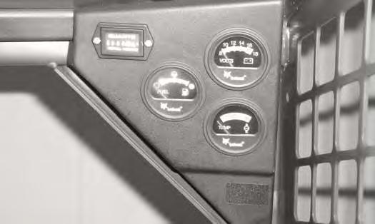

The instrument panels are shown in [Figure OI-1], [Figure OI-2] and [Figure OI-3] is ON when transmission charge pressure is low, hydraulic filter needs replacement or fluid temperature is high. Stop the engine if the light comes ON.
The table below shows the DESCRIPTION and FUNCTION/OPERATION for each of the components of the instrument panels.
BUTTON(Functions Only When The Seat Bar Is Raised.) Allows you to use the steering levers to move the loader forward or backward when using the backhoe attachment or for loader service. (See Page OI5.)
Only When The Seat Bar Is Down.) Activates BICS System when the Seat Bar is down and operator is seated in the operating position.
For starting and stopping the engine.
Light is ON when engine oil pressure is low or coolant temperature is high. Stop the engine if the light comes ON. 6 PREHEAT BUTTON the total operating hours of the loader.
Press to preheat the glow plugs to aid cold temperature starting. Switch will turn off when released.
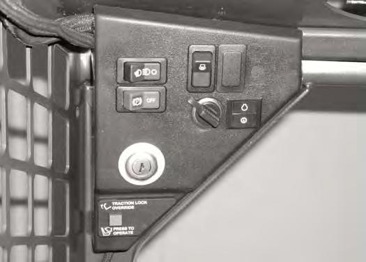
Press the left side of switch to turn lights ON; press right side to turn OFF. 8 PARKING BRAKE Press the left side of switch to engage; press right side to disengage. 9 BUCKET LEVEL SWITCH (Opt./FA)Controls the ON/OFF function of the available bucket position valve.
*Controls the available hazard lights. (Hazard Lights is a separate available accessory.) Both panel indicators blink for hazard condition when the hazard switch is ON. A red light indicates fuse out for taillights, headlights, work lights, etc. 16 flashing beacon or strobe light.
*Can be installed if you have a Deluxe Cab or a Cab Enclosure installed. (Opt.) - Option; (FA) - Field Accessory
BOBCAT INTERLOCK CONTROL SYSTEM (BICS™)
Description
The Bobcat Interlock Control System (BICS™) requires the operator to be seated in the operating position with the Seat Bar fully lowe red and the green PRESS TO OPERATE Button activated before the lift, tilt and traction functions can be operated. The Seat Belt must be fastened anytime you operate the loader.
NOTE:Press the green PRESS TO OPERATE Button again if the Seat Bar is raised and lowered or key is turned off.
Lift Arm By-Pass Control
The lift, tilt and traction drive functions are interlocked with the Seat Bar.
The BICS controller is located inside the cab; behind and to the right of the operator's seat [Figure OI-4]

There are five green lights on the BICS controller and all must be ON to operate the loader.
The light functions are as follows [Figure OI-4]:
1. SYSTEM ACTIVATED - ON when the green PRESS TO OPERATE Button is activated.
2. SEAT BAR - ON when the seat bar is down.
3. VALVE - ON when lift and tilt hydraulic functions can be used.
4. TRACTION - ON when loader can be moved forward and backward.
5. POWER - ON when the Controller is operating correctly.
NOTE: If any of the lights are off or blinking, (See BOBCAT INTERLOCK CONTROL SYSTEM (BICS™) on Page PM-12) or (See Troubleshooting Chart on Page SA-5).
The lift arm by-pass control knob (Item 1) [Figure OI-5] is used to lower the lift arms in the event that the lift arms cannot be lowered during normal conditions.
With the operator in the seat, seat belt fastened and the seat bar fully lowered, pull and hold the by-pass control knob (Item 1) [Figure OI-5] up. Push the top (toe) of the left (lift) pedal. The lift arms will slowly lower.

BOBCAT INTERLOCK CONTROL SYSTEM (BICS™) (CONT’D)
Traction Lock Override
Warning
AVOID INJURY OR DEATH
Before you leave the operator’s seat:
•Lower the lift arms, put the attachment flat on the ground.
•Stop the engine.
•Engage the parking brake.
•Raise seat bar, move pedals until both lock. W-2045-1086
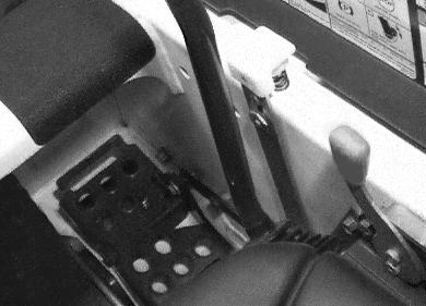
ENGINE SPEED CONTROL Operation
Figure OI-7
(Functions Only When The Seat Bar is Raised) There is a traction lock override button (Item 1) [Figure OI-6] on the left hand instrument panel. It allows you to use the steering levers to move the loader forward and backward when using the backhoe attachment or for service.
•Press the button once to unlock traction drive (green traction light on BICS Controller will be ON).
•Press the button a second time to lock the traction drive (green traction light on BICS Controller will be OFF.
NOTE:The traction Lock Override button will unlock the traction drive when the operator is NOT in the seat and the seat bar is raised.
NOTE:The traction Lock Override button will function if brake is engaged or disengaged position.
The engine speed control (Item 1) [Figure OI-7] is at the right side of the operator’s seat. Move the engine speed control forward to increase the engine RPM and backward to decrease the engine RPM.
Parking Brake
Operation
Figure OI-8
Press the left side of the switch (Item 1) [Figure OI-8] to engage the parking brake. Press the right side to disengage.
Steering Levers
Operation
Warning
AVOID INJURY OR DEATH
When operating the machine:
•Keep the seat belt fastened snugly.
•The seat bar must be lowered.
•Keep your feet on the pedal controls.
The steering levers (Item 1) [Figure OI-9] are on the right and left side in front of the seat.

Move the levers smoothly. Avoid sudden starting and stopping.
W-2046-0595
The steering levers control fo rward and reverse travel of the loader [Figure OI-10]
Forward Travel - Push both levers forward.
Reverse Travel - Pull both levers backward.
Normal Turning - Move one lever farther forward than the other.
Fast Turning - Push one lever forward and pull the other lever backward.
Slow travel speed, push levers forward only small amount.
To increase travel speed, push the levers farther forward.
For maximum pushing force, push the levers forward only a small amount with the engine at full RPM.
STOPPING THE BOBCAT LOADER Procedure
When the steering levers are moved to the NEUTRAL POSITION, the hydrostatic transmission will act as a service brake and stop the loader.
Seat Bar Restraint System
Warning
Before you leave the operator’s seat:
•Lower the lift arms, put the attachment flat on the ground.
•Stop the engine.
•Engage the parking brake.
•Raise the seat bar, move pedals until both lock.
•Move auxiliary control out of detent position.
W-2164-1294
The seat bar restraint system has a pivoting seat bar (Item 1) [Figure OI-11] with arm rests and has spring loaded interlocks for the lift and tilt control pedals.
The operator controls the use of the seat bar. The seat bar in the down position helps to keep the operator in the seat.

The interlocks require the ope rator to lower the seat bar in order to operate the foot pedal controls.
When the seat bar is up, the lift and tilt control pedals are locked when returned to the NEUTRAL POSITION.
Warning
AVOID INJURY OR DEATH
When operating the machine:
•Keep the seat belt fastened snugly.
•The seat bar must be lowered.
•Keep your feet on the pedal controls.
W-2046-0595
The spring loaded interlocks (Item 1) [Figure OI-12] control the locking and unlocking functions of the control pedals.
The interlocks (Item 1) [Figure OI-12] require the operator to lower the seat bar (Item 2) [Figure OI-12] which allows the operator to move the foot pedals to control the lift and tilt functions.
When seat bar is lowered, it pushes the interlocks (Item 1) [Figure OI-12] down on both sides, releasing the pedal linkages (Item 3) [Figure OI-12] from the interlocks.
The pedals will pivot in both directions when the interlock is down.
Warning
AVOID INJURY OR DEATH
The seat bar system must lock the lift and tilt control pedals in neutral when the seat bar is up. Service the system if pedals do not lock correctly.