5 minute read
Head-Up Display (HUD


Vacuum Fluorescent Display(VFD)
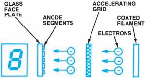
This is the most commonly used display for automotive electronic instruments, primarily because of its durability and bright display qualities. The vacuum fluorescent display (VFD) generates light similar to a television picture tube, with free electrons from a heated filament striking phosphor material that emits a blue-green light (Figure 13-31).
The anode segments are coated with a fluorescent material such as phosphorous. The filament is resistance wire, heated by electrical current. The filament coating produces free electrons, which are accelerated by the electric field generated by the voltage on the accelerating grid. High voltage is applied only to the anode of those segments required to form the characters to be displayed. Since the anode is at a higher voltage than the fine wire-mesh grid, the electrons pass through the grid. The phosphors on the segment anodes impressed with high voltage glow very brightly when struck by electrons; those receiving no voltage do not glow. The instrument computer determines the segments necessary to emit light for any given message and applies the correct sequences of voltage at the anodes.
VFD displays are extremely bright, and their intensity must be controlled for night viewing. This can be done by varying the voltage on the accelerating grid: the higher the voltage, the brighter the display. Intensity can also be controlled by pulse-width dimming, or turning the display on and off very rapidly while controlling the duration of on-time. This is similar to the pulse-width modulation of a carburetor mixture control solenoid or a fuel injector. The on-off action occurs so rapidly that it cannot be detected by the human eye.
Figure 13-31. In a vacuum fluorescent display, voltage applied selectively to segment anodes makes the
fluorescent material glow. (DaimlerChrysler Corporation) Cathode Ray Tube (CRT) Another display device used in automotive instrumentation was the cathode-ray tube (CRT), as used in the 1986–1996 Buick Riviera Buick Reatta.The CRT is essentially the same as the display used in an oscilloscope or a television set.CRTs function with an electron beam generated by an electron gun located at the rear of the tube.The CRT consists of a cathode that emits electrons and an anode that attracts them. Electrons are “shot”in a thin beam from the back of the tube.Permanent magnets around the outside neck of the tube and plates grouped around the beam on the inside of the tube shape the beam.A tube-shaped anode that surrounds the beam accelerates it as it leaves the electron gun. The beam has so much momentum that the electrons pass through the anode and strike a coating of phosphorus on the screen, causing the screen to glow at these points.The control plates are used to move the beam back and forth on the screen, causing different parts of it to illuminate.The result is a display (oscilloscope) or a picture (television).
The automotive CRT has a touch-sensitive Mylar switch panel installed over its screen.This panel contains ultra-thin wires, which are coded by row and column.Touching the screen in designated places blocks a light beam and triggers certain switches in the panel, according to the display mode desired.The switches in turn send a signal to the control circuitry, which responds by displaying the requested information on theCRT screen.In principle, this type of instrumentation combines two personal computer attributes:It has touch-screen control and is
menu driven.
HEAD-UP DISPLAY (HUD)
The head-up display (HUD) is a secondary display system that projects video images onto the windshield. It is an electronic instrumentation system (Figure 13-32) that consists of a special windshield, a HUD unit containing a computer module, and a system-specific dimmer switch.
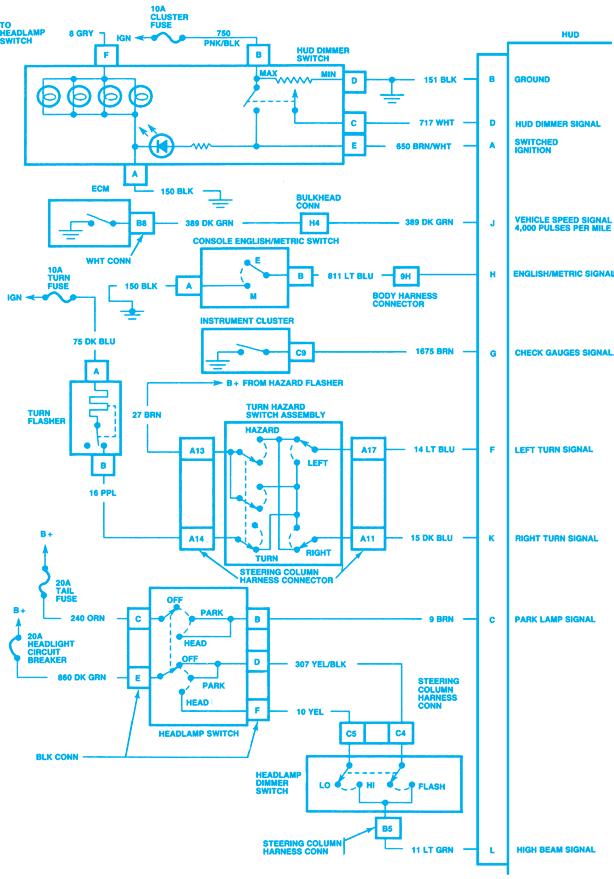
The HUD unit processes various inputs that are part of the instrument cluster and projects frequently used driver information on the windshield area for viewing from the driver’s seat. The dimmer switch provides system power for the computer module, varies the intensity of the display unit, and can change the vertical position of the display image through a mechanical cable drive system. When the ignition is turned on, the HUD unit performs a self-check routine and projects the following image (Figure 13-33) for approximately 3.5 seconds:
• Turn signal indicators • High-beam indicator • Check gauges indicator • Speed (km/h or mph) indicator • All segments of the digital speedometer
After completing the self-check, the system begins normal operation. The ECM provides vehicle speed information for HUD operation by completing a ground path to the HUD unit 4,000 times per mile. Each time the HUD unit recognizes a voltage drop at terminal J, it counts one pulse. By counting the pulses per second, the HUD unit can determine vehicle speed and project the corresponding figure on the windshield display.
Night Vision Head-Up Display(HUD)
The night vision system (Figure 13-34) used on the 2002–2003 Cadillac Deville is a monochromatic (single-color) option available to improve the vision of the driver beyond the scope of the headlamps. The night vision operates only under the following conditions: • The ignition is on. • The front fog lamps or the headlamps are onduring low light conditions. The night vision system uses the signal from the ambient light sensor to determine when low-light conditions exist. • The night vision system is on. The night vision system contains the following components: • The head-up display (HUD) • The head-up display (HUD) switches • The night vision camera
Head-Up Display (HUD)
Night vision uses a HUD to project the night vision video images onto the windshield. The HUD projects the detected object images onto the windshield based on the video signals from the night vision camera.
Head-Up Display Switches
• On/Off and Dimming Switch: This turns the
HUD display and the night vision system on or off. When the HUD is turned on, the system warm-up logo is displayed for a period of approximately 45 seconds. The on/off and dimming switch is also used to adjust the brightness of the video image. Moving the switch up will increase the HUD video image brightness. Moving the switch down will decrease the HUD video image brightness. • Up/Down Switch: The HUD in the night vision system has an electric tilt adjust motor that adjusts the video image to the preferred windshield location of the driver.
Pressing the Up/Down switch directs the tilt motor to adjust the night vision video image up or down, within a certain range.
Night Vision Camera
The night vision camera senses the heat given off by objects that are in the field of view of the camera. Warmer objects, such as pedestrians, animals, and other moving vehicles, appear whiter on the displayed image. Colder objects, such as the sky, signs and parked vehicles, appear darker on the displayed image. The night vision camera sends the detected object image information to the HUD via the high video signal circuit and the low video signal circuit.
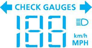
Figure 13-33. The HUD system display image. (GM


