
5 minute read
Malfunction Indicator Lamp (MIL


engine speed in revolutions per minute (rpm). These usually have an electromagnetic movement. The engine speed signals may come from an electronic pickup at the ignition coil (Figure 13-10). Voltage pulses taken from the ignition system are processed by solid-state circuitry into signals to drive the tachometer pointer. The pointer responds to the frequency of these signals, which increase with engine speed. Afilter is used to round off the pulses and remove any spikes.
Late-model vehicles with an engine control system may control the tachometer through an electronic module. This module is located on the rear of the instrument cluster printed circuit board andis the interface between the computer and tachometer in the same way the solid-state circuitry processes the ignition system-totachometer signals described earlier.
Figure 13-10. This GM HEI (high energy ignition) distributor has a special connector for a tachometer.
(GM Service and Parts Operations)
Vehicles with electronic engine control systems generally have a computer-operated warning lamp on the instrument panel to indicate the need for service. In the past, this was called aCheck Engine, Service Engine Soon, Power Loss, or Power Limited lamp, according to themanufacturer, as shown in the sample instrument cluster in Figure 13-11. To eliminate confusion, all domestic manufacturers now refer to it as a malfunction indicator lamp (MIL).
The MILlamp alerts the driver to a malfunction in one of the monitored systems. In some vehicles built before 1995, the MILis used to retrieve the faults or trouble codes stored in the computer memory by grounding a test terminal in the diagnostic connector. Like other warning lamps, the MILcomes on briefly as a bulb check when the ignition is turned on.
Seatbelt-Starter Interlocks During 1974 and early 1975, U.S.federal safety standards required a seatbelt-starter interlock system on all new cars.The system required frontseat occupants to fasten their seatbelts before the car could be started.This particular standard was repealed by an act of Congress in 1975.Now, most interlock systems have been disabled so that only a warning lamp and buzzer remain.
Antilock Brake System (ABS) Warning Lamp
Vehicles with ABS have a computer-operated amber antilock warning lamp (Figure 13-12) in addition to the MILand the standard red brake
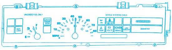
Figure 13-11. Malfunction indicator lamp in the instrument panel. (DaimlerChrysler Corporation)

Figure 13-12. ABS lights. (DaimlerChrysler Corporation)
lamp. The antilock lamp serves the same functions for the ABS that the MILlamp does for engine control systems as follows, • Lights to warn of a system problem that inhibits ABS operation • Retrieves trouble codes in the same way as the MILlamp (specific vehicles only) • Lights briefly at the beginning of an ignition cycle as a bulb check and to notify the driver that self-diagnostics are taking place
Buzzers,Tone Generators, Chimes,and Bells
Buzzers are a special type of warning device. They produce a loud warning sound during certain operating conditions, such as the following: • Seatbelts not fastened • Door open with key in ignition • Lights left on with engine off • Excessive vehicle speed A typical buzzer (Figure 13-13) operates in the same way as a horn. Instead of moving a diaphragm, the vibrating armature itself creates the sound waves. In Figure 13-13, two conditions are required to sound the buzzer: The door must be open, and the key must be in the ignition. These conditions close both switches and allow current to flow through the buzzer armature and coil.
Most warning buzzers are separate units mounted on the fuse panel or behind the instrument panel. GM vehicles may have a buzzer built into the horn relay (Figure 13-14). When the ignition key is left in the switch and the door is opened, a small amount of current flows through

Figure 13-13. Current will flow through this warning buzzer only when both switches are closed—when the door is open and the key is in the ignition switch.
Figure 13-14. GM cars may have a buzzer built into the horn relay. Here, the buzzer is activated because both the door switch and the key switch are closed.

(GMService and Parts Operations)
the relay coil. The magnetic field is strong enough to operate the buzzer, but it is not strong enough to close the horn contacts.
Grounding switches usually activate buzzers. A timing circuit can be built into the buzzer by winding a heater coil around an internal circuit breaker (Figure 13-15) and connecting the heater coil directly to ground. When current flows to the buzzer, a small amount of current flows through the heater coil to ground. When the coil is hot enough, it will open the circuit breaker and keep it open. Current through the buzzer will stop even though the grounding switch is still closed.
Some typical buzzer warning circuits are shown in Figures 13-16and 13-17. Figure 13-17includes a prove-out circuit branch with a manual-grounding switch that the driver can close to check that the bulb and buzzer are still working. Some prove-out circuits operate when the ignition switch is at START, to show the driver if any bulbs or buzzers have failed.
Tone generators, chimes, and bells are mechanical devices that produce a particular sound when voltage is applied across a sound bar. Various sounds are obtained by varying the voltage. Like buzzers, they are replaced if defective.
The circuit shown in Figure 13-18is the circuit diagram for an electronic temperature gauge. Thecoolant temperature sensor is an NTC thermistor with high resistance at low temperatures and low resistance at high temperatures. When a cold engine is first started, the sensor’s resistance is very high, resulting in a low voltage output to the gauge display, which translates into a low

Figure 13-15. This buzzer will sound for only a few seconds each time it is activated, because of the circuit breaker and heater coil built into the unit.
(GMService and Parts Operations)
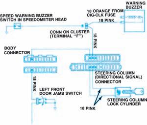
Figure 13-16. In this circuit, one buzzer responds both to excessive speed and to driver door position.
(GM Service and Parts Operations) Figure 13-17. This warning buzzer will be activated if engine coolant temperature rises above a safe level.
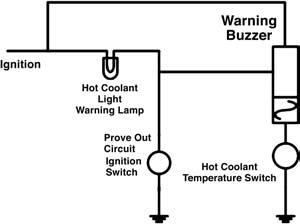

Figure 13-18. GM’s electronic temperature gauge circuit is similar to that of an analog gauge. (GM Service
and Parts Operations)


