
1 minute read
Backup Lamp Circuits Side Marker and Clearance Lamp


Figure 12-41. The hazard flasher is constructed to control a large amount of current.
is closed and current flows to the flasher, the high resistance of the coil does not allow enough current to light the lamps. However, the coil heats up and causes the bimetallic strip to close the contacts. The contacts form a parallel circuit branch and conduct current to the lamps. Decreased current flow through the coil allows it to cool and the bimetallic strip opens the contacts again. This cycle repeats about 30 times per minute.
BACKUP LAMP CIRCUITS
The white backup lamps light when the car’s transmission or transaxle is in reverse. The lamps have been used for decades, but have been required by law since 1971. Backup lamps and license plate lamps are the only white lamps allowed on the rear of a car.
Circuit Diagram
A typical backup lamp circuit diagram is shown in Figure 12-42. Figure 12-43shows integration of the backup lamp with the stop, taillamp, and turn signals in a typical rear lighting diagram. When the transmission switch is closed, the backup lamps receive current through the ignition switch. The lamps will not light when the ignition switch is off.
Switches and Fuses
The backup lamp switch generally is installed on the transmission or transaxle housing (Figure 12-43), but it may be mounted near the gear selector lever (Figure 12-42) on some vehicles. The backup switch may be combined with the neutral safety switch. A15- to 20-ampere fuse, which often is shared with other circuits, protects the circuit.

Figure 12-42. A typical backup lamp circuit.
(DaimlerChrysler Corporation)
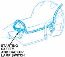
Figure 12-43. The backup lamp switch can be mounted on the transmission housing. (DaimlerChrysler
Corporation)

Figure 12-44. The backup lamp switch can be mounted near the gearshift lever. (GM Service and Parts
Operations)


