
6 minute read
Stop Lamp and Turn Signal Circuits Hazard Warning Lamp (Emergency Flasher)


Figure 12-31. A taillamp, license plate lamp, and parking lamp circuit diagram. (GM Service and Parts Operations)
Switches and Fuses
These lamps are controlled by contacts within the main headlamp switch. They can be lit when the headlamps are off (Figure 12-32). Afuse (usually 20 amperes) protects the circuit.
Bulbs
The bulb designs most commonly used as taillamps and parking lamps are the G-6 single-contact bayonet and the S-8 double-contact bayonet. The tail and parking lamps may each be one filament of a double-filament bulb. License plate lamps are usually G-6 single-contact bayonet or T-3 1/4-wedge bulbs.
STOP LAMP AND TURN SIGNAL CIRCUITS
Stop lamps, also called brake lamps, are always red. Federal law requires a red center highmounted stop lamp (CHMSL), on 1986 and later

Figure 12-32. Contacts in the main headlamp switch provide current to the taillamps, license plate lamps,
and parking lamps. (DaimlerChrysler Corporation)
models. Turn signals, or directionals, are either amber or white on the front of the car and either red or amber on the rear.
Circuit Diagram
A typical circuit diagram with stop and turn lamps as separate bulbs is shown in figure 12-38A. When the brakes are applied, the brake switch is closed and the stop lamps light. The brake switch receives current from the fuse panel and is not affected by the ignition switch.
When the turn signal switch is moved in either direction, the corresponding turn signal lamps receive current through the flasher unit. The flasher unit causes the current to start and stop very rapidly, as we will see later. The turn signal lamp flashes on and off with the interrupted current. The turn signal switch receives current through the ignition switch, so that the signals will light only if the ignition switch is on.
In many cars, the stop and turn signals are bothprovided by one filament, as shown in Figure 12-33Band Figure 12-34. When the turn signal switch is closed, the filament receives interrupted current through the flasher unit. When the brakes are applied, the filament receives a steady flow of current through the brake switch and special contacts in the turn signal switch. If both switches are closed at once, brake switch current is not allowed through the turn signal switch to the filament on the signaling side. The signaling filament receives interrupted current through the flasher unit, so it flashes on and off. The filament on the opposite side of the car receives a steady flow of current through the brake switch and the turn signal switch, so it is continuously lit. Figure 12-34shows the integration of the single-filament CHMSLin a typical stop-and-turn signal circuit.
Switches,Fuses,and Flashers
Several units affect current flow through the stop lamp and turn signal circuits. The ignition switch is located between the battery and the turn signal switch (Figure 12-35), so the current cannot flow through the turn signal switch if the ignition switch is off. The ignition switch does not control the brake switch; it is connected directly to battery voltage through the fuse panel (Figure 12-35).
Before the mid-1960s, the brake switch was often located within the brake hydraulic system and operated by hydraulic pressure. Because of changes in braking system design, this type of switch is no longer commonly used. On latemodel cars, the brake switch is usually mounted
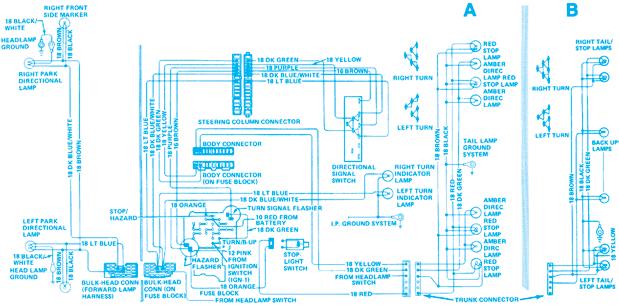
Figure 12-33. Stop lamp and turn signal circuits. The basic drawing (A) has separate bulbs for each function. The alternate view of the rear lamps (B) has single bulbs with double filaments. One filament of each bulb works for stop
lamps and for turn signals. (GM Service and Parts Operations)

Figure 12-34. A typical rear lighting circuit diagram showing the inclusion of the center high-mounted stop lamp (CHMSL) mandated by law on 1986 and later models. (DaimlerChrysler Corporation)
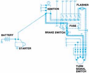
Figure 12-35. The ignition switch controls current to the turn signal switch, but does not affect current to the brake switch.
on the bracket that holds the brake pedal. When the pedal is pressed, the switch is closed.
The turn signal switch is mounted within thesteering column and operated by a lever (Figure 12-36). Moving the lever up or down
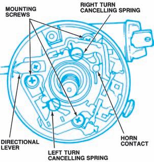
Figure 12-36. The turn signal switch includes various springs and cams to control the contact points.

Figure 12-37. When the stop lamps and turn signals share a common filament, stop lamp current flows through the turn signal switch.
closes contacts to supply current to the flasher unit and to the appropriate turn signal lamp. A turn signal switch includes cams and springs that cancel the signal after the turn has been completed. That is, as the steering wheel is turned in the signaled direction and then returns to its normal position, the cams and springs separate the turn signal switch contacts.
In systems using separate filaments for the stop and turn lamps, the brake and turn signal switches are not connected. If the car uses the same filament for both purposes, there must be a way for the turn signal switch to interrupt the brake switch current and allow only flasher unit current to the filament on the side being signaled. To do this, brake switch current is routed through contacts within the turn signal switch (Figure 12-37). By linking certain contacts, the bulbs can receive either brake switch current or flasher current, depending upon which direction is being signaled.
For example, Figure 12-38shows current flow through the switch when the brake switch is closed and a right turn is signaled. Steady current through the brake switch is sent to the left brake lamp. Interrupted current from the turn signal is sent to the right turn lamps.
Flasher units supply a rapid on-off-on current to the turn signal lamps. To do this, they act very much like Type 1 self-setting circuit breakers. Current flows through a bimetallic arm (Figure 12-39), heating the arm until it bends and opens a set of contact points. When the current stops, the arm cools and the contact points close again. This cycle occurs rapidly so that the turn signal lamps flash on and off about once every second. Flasher units usually are installed in the wiring harness beneath the instrument panel or in the fuse panel.
Some manufacturers use two flashers, one for the turn signals and one for the hazard warning lamps. Other manufacturers use a single flasher that controls both the turn signals and the hazard warning lamps. This type of flasher is called a combination flasher.

Figure 12-38. When a right turn is signaled, the turn signal switch contacts send flasher current to the righthand filament and brake switch current to the left-hand filament.

Figure 12-39. The internal components of a turn signal flasher.


