16 minute read
Headlamp Circuits


The headlamp circuit is one of the most standardized automotive circuits, because headlamp use is regulated by laws that until recently had seen little change since the 1940s. There are two basic types of headlamp circuits, as follows: • Two-lamp circuit • Four-lamp circuit
Manufacturers select the type of circuit on the basis of automotive body styling. Each circuit must provide a high-beam and a low-beam light, a switch or switches to control the beams, and a high-beam indicator.
Circuit Diagrams
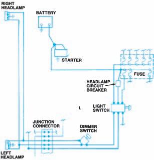
Most often, the headlamps are grounded and switches are installed between the lamps and the power source, as shown in Figure 12-1. Some circuits have insulated bulbs and a grounded switch, as shown in Figure 12-2. In both cases, all lamp filaments are connected in parallel. The failure of one filament will not affect current flow through the others.
A two-lamp circuit (Figure 12-3) uses lamps that contain both a high-beam and a low-beam filament. Afour-lamp circuit (Figure 12-4) has two double-filament lamps and two lamps with single, high-beam filaments. Lamp types are explained in more detail later in this chapter.
Figure 12-1. Most headlamp circuits have insulated switches and grounded bulbs.
Switches and Circuit Breakers
The three operating conditions of a headlamp circuit are as follows: • Off—No current • Low-beam—Current through low-beam filaments • High-beam—Current through both the low-beam and the high-beam filaments
One or two switches control these current paths; the switches may control other lighting circuits as well. Most domestic cars have a main headlamp switch with three positions, as shown in Figure 12-5.

Figure 12-2. Some headlamp circuits use grounded switches and insulated bulbs. (GM Service and Parts
Operations)
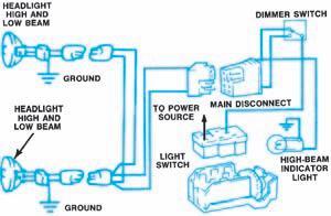
Figure 12-3. A two-lamp headlamp circuit uses two double-filament bulbs.
Figure 12-4. A four-lamp headlamp circuit uses two double-filament bulbs and two single-filament bulbs.
• First position—Off, no current. • Second position—Current flows to parking lamps, taillamps, and other circuits. • Third position—Current flows to both the second-position circuits and to the headlamp circuit.
The headlamp switch is connected to the battery whether the ignition switch is on or off. Atwoposition dimmer switch is connected in series with the headlamp switch. The dimmer switch controls the high- and low-beam current paths. If the headlamps are grounded at the bulb, as shown in Figure 12-6, the dimmer switch is installed between the main headlamp switch andthe bulbs. If the headlamps are remotely grounded, as shown in Figure 12-2, the dimmer switch is installed between the bulbs and ground.
The dimmer switch on older cars and most lightduty trucks is foot operated and mounted near the pedals. On late-model cars, it generally is mounted on the steering column and operated by a multifunction stalk or lever, as shown in Figure 12-7. Some imported and late-model domestic cars use a

Figure 12-5. The main headlamp switch controls both the headlamp circuit and various other lighting
circuits. (DaimlerChrysler Corporation)

Figure 12-6. Most dimmer switches are insulated and control current flow to grounded bulbs. (DaimlerChrysler
Corporation)

Figure 12-7. Late-model dimmer switches are operated by a steering column-mounted multifunction stalk or lever and control other lamp circuits. (GM Service and Parts Operations)

Figure 12-8. Headlamp switches may be mounted on the steering column and operated by a stalk or lever.
single switch to control all of the headlamp circuit operations. The following basic types of headlamp switches are used:
• Mounted on the steering column and operated by a lever (Figure 12-8) • A push-pull switch mounted on the instrument panel (Figure 12-9) • A rocker-type switch mounted on the instrument panel (Figure 12-10)
All systems must have an indicator lamp for high-beam operation. The indicator lamp is mounted on the instrument panel. It forms a parallel path to ground for a small amount of highbeam current and lights when the high-beam filaments light.
Because headlamps are an important safety feature, a Type 1, self-setting circuit breaker protects the circuitry. The circuit breaker can be built into the headlamp switch, as shown in Figure 12-5, or it can be a separate unit, as shown in Figure 12-1.

Figure 12-9. Push-pull headlamp switches are mounted on the instrument panel.

Figure 12-10. Rocker-type headlamp switches usually have a separate rotary rheostat control. (GM Service
and Parts Operations)
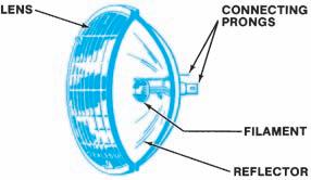
Figure 12-11. A cutaway view of a conventional sealed-beam headlamp.
Headlamps Until 1940, a small replaceable bulb mounted behind a glass lens was used to provide light for night driving.Safety standards established in the United States in 1940 made round, sealed-beam units mandatory on domestic cars. Repeated attempts to modify the standards after World War II were only partially successful, beginning with the introduction of rectangular sealed-beam units in the mid-1970s.The first major change in headlight design came with the rectangular halogen headlamp, which appeared on some 1980 models. Since that time, considerable progress has been made in establishing other types, such as composite headlamps that use replaceable halogen bulbs.
Conventional Sealed-Beam Headlamps
A sealed-beam headlamp is a one-piece, replaceable unit containing a tungsten filament, a reflector, a lens, and connecting terminals, as shown in Figure12-12. The position of the filament in front of the reflector determines whether the filament will cast a high or a low beam. The glass lens is designed to spread this beam in a specific way. Headlamps have symmetrical or asymmetrical beams, as shown in Figure 12-12. All high beams are spread symmetrically; all low beams are spread asymmetrically.
Halogen Sealed-Beam Headlamps
Halogen sealed-beam headlamps (Figure 12-13) first appeared as options on some 1980 domestic cars. Their illumination comes from passing current

Figure 12-12. The glass lens design determines whether the beam is symmetrical or asymmetrical.
Halogen filled inner bulb Lens
Filament
Hermetically sealed housing
Figure 12-13. Halogen sealed-beam headlamps.
(DaimlerChrysler Corporation)
through a filament in a pressure-filled halogen capsule, instead of through a filament in a conventional evacuated sealed-beam bulb. Halogen lamps provide brighter, whiter light than conventional headlamps.
Service and adjustment procedures are the same for halogen sealed-beam lamps as they are for conventional sealed-beams. Early bulb-type halogen lamps were not interchangeable with conventional sealed-beam headlamps, but today halogen sealedbeam lamps can often be used as direct replacements for their conventional counterpart. Halogen lamps are manufactured of glass or plastic. Glass lamps carry an “H” prefix; plastic lamps have an “HP” prefix. Plastic lamps are less susceptible to
stone damage and also weigh considerably less than glass lamps.
Historical Headlamp Control Levers Late-model cars are not the first to have a columnmounted lever controlling the headlamp circuit.The headlamps on the 1929 REO Wolverine Model B were turned on and off by a lever mounted to the left of the horn button on the steering wheel.This lever also controlled the high-low beam switching. The REO instruction book pointed out that, because each headlamp filament produced twenty-one candlepower, the headlamps should not be used when the car was standing still, to avoid draining the battery.
Halogen sealed-beam lamps are manufactured in the same sizes and types as conventional sealed-beams, with one additional type, as follows:
• Type 2E lamps contain both a high-beam and a low-beam inside a rectangular, 4 × 6 1/2-inch (102 × 165-mm) housing.
Like conventional sealed-beams, the type code and aiming pads are molded into the lens of the bulb.
Composite Headlamps
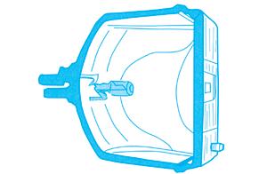
Composite headlamps first appeared on some 1984 models as a part of the aerodynamic styling concept that has characterized car design since the mid-1980s. Composite headlamp design uses a replaceable halogen headlamp bulb that fits into a socket at the rear of the reflector, as shown in Figure 12-14. Since the headlamp housing does not require replacement unless damaged, it can be incorporated as a permanent feature of automotive styling. The housing can be designed to accept a single bulb or dual bulbs.
Composite headlamps can be manufactured by two different methods. In one, polycarbonate plastic is used to form the lens portion of the headlamp housing, as shown Figure 12-15, and the inside of the housing is completely sealed. In the other, a glass lens cover is permanently bonded with a reflector housing to form a single unit. Because this type of composite headlamp is vented to the atmosphere, water droplets may form on the inside of the glass lens cover when the headlamps are off. Such condensation disappears rapidly when the lights are turned on and does not affect headlamp performance.
Replacement halogen bulbs may contain both high- and low-beam filaments for use in twoheadlamp systems, and individual high- or lowbeam filaments for use in four-headlamp systems. The halogen bulbs have a quartz surface that can be easily stained when handled. For this reason, the bulbs are furnished in protective plastic covers that should not be removed until the bulb has been installed. If the quartz surface is accidentally touched with bare hands, it should be cleaned immediately with a soft cloth moistened with alcohol.

Figure 12-14. A replaceable halogen bulb is installed through the rear of the reflector and held in place with a
retaining ring. (GM Service and Parts Operations)

Figure 12-15. Composite headlights use a polycarbonate lens and form a permanent part of the car’s
styling. (GM Service and Parts Operations)
Figure 12-16. Common sealed-beam headlamps and replaceable halogen bulbs. (GM Service and Parts Operations)
Replacing the halogen bulb in a composite headlamp does not normally disturb the alignment of the headlamp assembly. There should be no need for headlamp alignment unless the composite headlamp assembly is removed or replaced. If alignment is required, however, special adapters must be used with the alignment devices. Figure 12-16describes the automotive headlamps currently in use.

High-Intensity Discharge (HID) Lamps
The latest headlight development is the highintensity discharge (HID) lamp (Figure 12-17). These headlamps put out three times more light and twice the light spread on the road than conventional halogen headlamps. They also use about two-thirds less power to operate and will last two to three times as long. HID lamps produce light in both ultraviolet and visible wave-lengths, causing highway signs and other reflective materials to glow.
These lamps do not rely on a glowing element for light. Instead the HID lamp contains a pair of electrodes, similar to spark plug electrodes, surrounded by gas. The electrode is the
LEAD-IN INSULATOR ELECTRODES LAMP BODY
DISCHARGE CHAMBER
Figure 12-17. High-intensity discharge (HID) lamps.
end of an electrical conductor that produces a spark. Light is produced by an arc that jumps from one electrode to another, like a welder’s arc. The presence of an inert gas amplifies the light given off by the arcing. More than 15,000 volts are needed to jump the gap in the electrodes. To provide this voltage, a voltage booster and controller are required. Once the gap is bridged, only 80 volts is needed to keep the current flow across the gap. The large light output of the HID allows them to be smaller in size. HIDs will usually show signs of failure before they burn out.
Headlamp Location andMounting
State and federal laws control the installation of headlamps. Automotive designers must place headlamps within certain height and width ranges. In addition, two- or four-lamp systems must follow one of the patterns shown in Figure12-18.
Headlamps are mounted so that their aim can be adjusted. Most circular and rectangular lamps have three adjustment points, as shown in Figure 12-19. The sealed-beam unit is placed in an adjustable mounting, which is retained by a stationary mounting. Many cars have a decorative bezel that hides this hardware while stillallowing lamp adjustment, as shown in Figure12-20. Composite headlamps use a similar two-point adjustment system, as in Figure 12-21, but require the use of special adapters with the alignment devices.
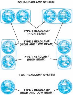
Figure 12-18. The law requires that headlamps be arranged in one of these patterns. The same requirements apply to rectangular lamps. Figure 12-19. Most sealed-beam headlamps have vertical and horizontal adjusting screws. (GM Service

and Parts Operations)

Figure 12-20. Headlamps are held in an adjustable mounting which is generally concealed by a decorative bezel.
Concealed Headlamps
Another automotive styling feature is concealed headlamps, either stationary lamps behind movable doors, as in Figure 12-22, or lamps that move in and out of the car’s bodywork as in, Figure 12-23. The doors can be metal or clear plastic.
Electric motors or vacuum actuators operate headlamp-concealing mechanisms. Electrically operated systems usually have a relay controlling current flow to the motor. Vacuum-actuated systems work with engine vacuum stored in a reservoir.
Federal law requires that the main headlamp switch control the concealing mechanisms on late-model cars and that “pop-up” headlamps that rise out of the hood must not come on until they have completed 75 percent of their travel. Switches used with electrically operated headlamp doors have additional contacts to activate the relay (Figure 12-24). Vacuum-actuated systems usually have a vacuum switch attached to the headlamp switch. Some older cars may have a separate switch to control the door. All concealed headlamp systems also must have a manual opening method, such as a crank or a lever, as a backup system.
Some 1967 and earlier cars have a clear plastic lens cover, or fairing, over the sealed-beam unit. These are not legal on later-model cars.

Figure 12-21. Composite headlamps also have vertical and horizontal adjustments. (GM Service and Parts
Operations)
Automatic Headlamp Systems
Photocells and solid-state circuitry are used to control headlamp operation in many vehicles today. Asystem can turn the lamps on and off; on past models they controlled the high- and lowbeam switching. Some parts can be adjusted, but defective parts cannot be repaired. All automatic
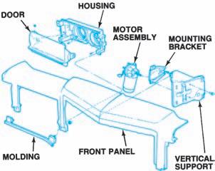
Figure 12-22. Headlamps can be concealed by a
movable door. (DaimlerChrysler Corporation)
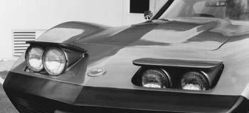
Figure 12-23. Headlamps can be concealed by moving them into and out of the car’s bodywork.
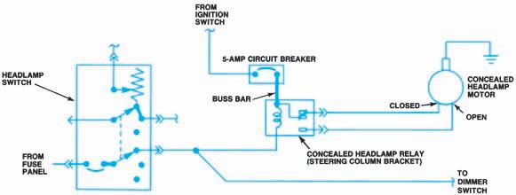
Figure 12-24. The main headlamp switch must operate the concealing mechanism. (DaimlerChrysler
Corporation)
systems have manual switches to override the automatic functions.
On-Off Control
The photocell or ambient light sensor used in this system may be mounted on top of the instrument panel (Figure 12-25) facing upward so that it is exposed to natural outside light. In some older applications it may be mounted to the rearview mirror assembly facing outward for exposure to outside light. The photocell voltage is amplified and applied to a solid-state control module. Photocell voltage decreases as outside light decreases. Most photocells are adjustable for earlier or later turn-on. At a predetermined low light and voltage level, the module turns the headlamps on. The module often contains time-delay circuitry, so that: • When the vehicle is momentarily in dark or light, such as when passing under a bridge or a streetlamp, the headlights do not flash on or off. • When the automobile’s ignition is turned off, the headlights remain on for a specified length of time and then are turned off.
Twilight Sentinel
GM luxury vehicles use a system called Twilight Sentinel. The twilight delay switch in the headlamp switch assembly is supplied a 5 volt reference from the instrument panel integration module (IPM) as shown in Figure 12-26. The

Figure 12-25. This photocell or ambient light sensor is mounted near the center of the dash panel and reacts to outside light to control the headlight on-off operation. The instrument panel integration module (IPM), which is the system amplifier is also shown. (GM
Service and Parts Operations)
IPM also provides ground to the twilight delay switch. The switch is a potentiometer in which the resistance varies as the switch is moved. The IPM receives an input voltage proportional to the resistance of the potentiometer through the twilight delay signal circuit. The IPM sends a class 2 message to the dash integration module (DIM) indicating the on/off status and delay length for the twilight sentinel. With the twilight sentinel switch in any position other than OFF, the DIM will turn the headlamps on or off according to the daytime/nighttime status sent by the IPM. The DIM uses the twilight delay signal in order to keep the headlamps and park lamps on after the

Figure 12-26. GM twilight sentinel.
ignition switch transitions from ON to OFF during nighttime conditions.
Daytime Running Lights
Daytime running lights (DRL) have been mandated for use in Canada and several other countries since 1990 and are included as standard equipment on General Motors vehicles since 1996 (Figure 12-27). The basic idea behind these lights is that dimly lit headlights during the day make the vehicle more visible to other drivers, especially when the sun is behind the vehicle during sunset or after dawn. Generally, when the ignition is on and it is not dusk or dark, the daytime running lights will be on. When it is dusk, the system operates like an automatic headlamp system.
The DRLsystems use an ambient light sensor, a light-sensitive transistor that varies its voltage signal to the body control module (BCM) in response to changes to the outside (ambient) light level. When the BCM receives this signal it will either turn on the DRLor the headlight relayfor auto headlamp operation. Any function or condition that turns on the headlights will cancel the daytime running lamps operation. TheDRLare separate lamps independent of theheadlamps. With the headlight switch in the OFF position, the DRLwill either be turned on or off after an approximately 8-second delay, depending on whether daylight or low light conditions are sensed. The DRL10-amp fuse in the engine wiring harness junction block supplies battery positive voltage to the DRLrelay switch contacts. The ignition 10-amp fuse in theengine wiring harness junction block supplies ignition positive voltage to the DRLrelay coil. When theBCM energizes the DRLrelay in daylight conditions, the current flows to both DRLlampsand to ground. The DRL will operate when the ignition switch is in the RUN position, the gear selector is not in the PARK position, and the parking brake is released. When these conditions have been met and the ambient light sensor indicates daytime conditions, the DRLwill illuminate.
Some systems channel the headlamp current through a resistor and reduce the current and power to the lights to reduce their daytime intensity. Others use pulse-width modulation (PWM) through a separate control module that modulates


