
8 minute read
Starter Motor and Drive Types


Figure 9-36. Armature wave winding.
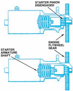
Figure 9-37. The pinion gear meshes with the flywheel ring gear.
the motor field circuit, which in turn eliminates the potential for field wire-to-frame shorts, field coil welding, and other electrical problems. The motor has only an armature circuit. Because the smaller armature in permanent magnet starters uses reinforcement bands, it has a longer life than the armature in wound-field starter motors.
The magnetic field of the starter motor is provided by four or six small permanent magnets. These magnets are made from an alloy of iron and rare-earth materials that produces a magnetic field strong enough to operate the motor without relying on traditional current-carrying field coil windings around iron pole pieces. Removing the field circuit not only minimizes potential electrical problems, the use of permanent-magnet fields allows engineers to design a gear-reduction motor half the size and weight of a conventional wound-field motor without compromising cranking performance.
See Chapter 9 of the Shop Manual for service and testing.

Figure 9-38. A four-brush motor. (Delphi Automotive
Systems)
Starter motors, as shown in Figure 9-39are direct-current (DC) motors that use a great amount of current for a short time. The starter motor circuit is a simple one containing just the

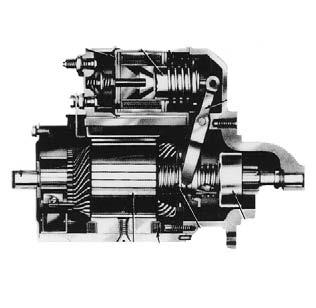
Figure 9-39. Starter motor cutaway.
starter motor and a solenoid or relay. This circuit is a direct path for delivering the momentary high current required by the starter motor from the battery.
The starter motor cranks the engine through a pinion gear that engages a ring gear on the engine flywheel. The pinion gear is driven directly off the starter armature (Figure 9-39) or through a set of reduction gears (Figure 9-40) that provides greater starting torque, although at a lower rpm.
For the starter motor to be able to turn the engine quickly enough, the number of teeth on the flywheel ring gear, relative to the number of teeth on the motor pinion gear, must be between 15 and 20 to 1 (Figure 9-41).
When the engine starts and runs, its speed increases. If the starter motor were permanently engaged to the engine, the motor would be spun at a very high speed. This would throw armature windings off the core. Thus, the motor must be disengaged from the engine as soon as the engine turns more rapidly than the starter motor has cranked it. This job is done by the starter drive. Four general kinds of starter motors are used in late-model automobiles:
• Solenoid-actuated, direct drive • Solenoid-actuated, reduction drive • Movable-pole shoe • Permanent-magnet, planetary drive

Figure 9-40. The Chrysler reduction-gear starter
motor. (DaimlerChrysler Corporation)

Figure 9-41. The ring-gear-to-pinion-gear ratio is about 20 to 1.
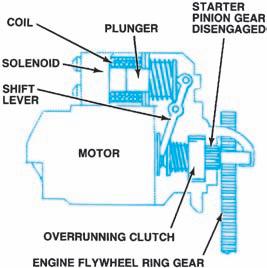
Figure 9-42. A typical solenoid-actuated drive.
Solenoid-Actuated, DirectDrive
The main parts of a solenoid-actuated, directdrive starter (Figure 9-42), are the solenoid, the shift lever, the overrunning clutch, and the starter pinion gear. The solenoid used to actuate a starter drive has two coils: the pull-in winding and the hold-in, or holding, winding (Figure 9-43). The pull-in winding consists of few turns of a heavy wire. The winding is grounded through the motor armature and grounded brushes. The hold-in winding consists of many turns of a fine wire and is grounded through the solenoid case.
When the ignition switch is turned to the start position, current flows through both windings. The solenoid plunger is pulled in, and the contacts are closed. This applies battery voltage to both ends of the pull-in winding, and current through it stops. The magnetic field of the hold-in winding is enough to keep the plunger in place. This circuitry reduces the solenoid current draw during cranking, when both the starter motor and the ignition system are drawing current from the battery.
The solenoid plunger action, transferred through the shift lever, pushes the pinion gear into mesh with the flywheel ring gear (Figure 9-44). When the starter motor receives current, its armature begins to turn. This motion is transferred through the overrunning clutch and pinion gear to the engine flywheel.
The teeth on the pinion gear may not immediately mesh with the flywheel ring gear. If this happens, a spring behind the pinion compresses so that the solenoid plunger can complete its stroke. When the motor armature begins to turn, the pinion teeth line up with the flywheel, and spring force pushes the pinion to mesh.
The Delco-Remy MT series, as shown in Figure 9-45, is the most common example of this type of starter motor and has been used for decades on almost all GM cars and light trucks. While this motor is manufactured in different sizes
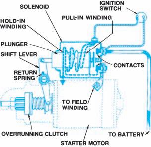
Figure 9-43. The solenoid has a heavy-gauge pull-in winding and a lighter-gauge hold-in winding. (Delphi
Automotive Systems)
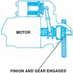
Figure 9-44. The movement of the solenoid plunger meshes the pinion gear and the flywheel ring gear.
RUBBER GASKET
GROMMET
BUSHING RETURN SPRING PLUNGER SOLENOID
SHIFT LEVER
PINION STOP
ARMATURE ASSIST SPRING
FIELD COIL OVERRUNNING CLUTCH
Figure 9-45. The Delco-Remy solenoid-actuated drive
motor. (Delphi Automotive Systems)
for different engines (Figure 9-46), the most common application is a four-pole, four-brush design. The solenoid plunger action, in addition to engaging the pinion gear, closes contact points to complete the starter circuit. To avoid closing the contacts before the pinion gear is fully engaged, the solenoid plunger is in two pieces (Figure 9-47). When the solenoid windings are magnetized, the first plunger moves the shift lever. When the pinion gear reaches the flywheel, the first plunger has moved far enough to touch the second plunger. The first plunger continues to move into the solenoid, pushing the second plunger against the contact points.
A similar starter design has been used by Ford on diesel engines and older large-displacement V8 gasoline engines. It operates in the same way as the starter just described. The solenoid action closes a set of contact points.
Because Ford installs a remotely mounted magnetic switch in all of its starting circuits, the solenoid contact points are not required to control the circuit. The solenoid contact points are physically linked, so that they are always “closed.”
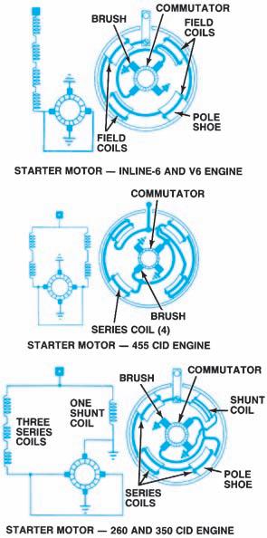
Figure 9-46. Delco-Remy provides differently connected starter motors for use with various engines.
(GM Service and Parts Operations)
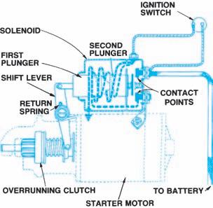
Figure 9-47. The Delco-Remy solenoid plunger is in
two pieces. (Delphi Automotive Systems)
In the early 1970s, Chrysler also manufactured fully enclosed direct-drive starter motor. It works in the same way as the solenoid-actuated starters previously described. The solenoid plunger closes contact points to complete the motor circuitry, but the system also has a remotely mounted starter relay. Reduction-drive starters are usually compound motors. Most Bosch and all Japanese starter motors operate on the same principles.
Solenoid-Actuated, ReductionDrive
The Chrysler solenoid-actuated, reduction-drive starter uses a solenoid to engage the pinion with the flywheel and close the motor circuit. The motor armature does not drive the pinion directly, however; it drives a small gear that is permanently meshed with a larger gear. The armature-gearto-reduction-gear ratio is between 2 and 3.5 to 1, depending upon the engine application. This allows a small, high-speed motor to deliver increased torque at a satisfactory cranking rpm. Solenoid and starter drive operation is basically the same as a solenoid-actuated, direct-drive starter.
Movable-Pole-Shoe Drive
Manufactured by the Motorcraft Division of Ford, the movable-pole-shoe starter motor is used on
most Ford automobiles (Figure 9-48). One of the motor-pole shoes pivots at the drive end housing. The field winding of this shoe also contains a holding coil, wired in parallel and independently grounded. When the starter relay is closed, battery current flows through the field windings and the holding coil of the pole shoe to ground. This creates a strong magnetic field, and the pole shoe is pulled down into operating position. The motion is transferred through a shift lever, or drive yoke, to mesh the pinion gear with the ring gear.
When the pole shoe is in position, it opens a set of contacts. These contacts break the ground connection of the field windings. Battery current is allowed to flow through the motor’s internal circuitry, and the engine is cranked. During cranking, a small amount of current flows through the holding coil directly to ground to keep the shoe and lever assembly engaged.
An overrunning clutch prevents the starter motor from being turned by the engine. When the ignition switch moves out of the start position, current no longer flows through the windings of the movable pole shoe or the rest of the motor. Spring force pulls the shoe up, and the shift lever disengages the pinion from the flywheel.
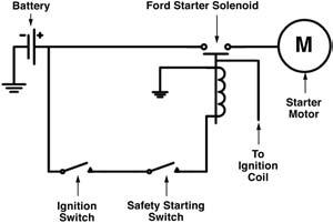
Figure 9-48. Circuit diagram of a system using a movable-pole-shoe starter.
Permanent-Magnet PlanetaryDrive
The high-speed, low-torque permanent-magnet planetary-drive motor operates the drive mechanism through gear reduction provided by a simple planetary gearset. Figure 9-49shows the Bosch gear reduction design, which is similar to that used in Chrysler starters. Figure 9-50shows the


