5 minute read
DC Starter Motor Operation


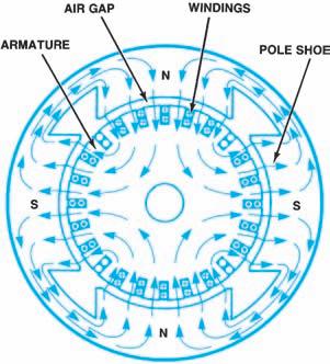
Figure 9-28. Flux path in a four-pole motor.
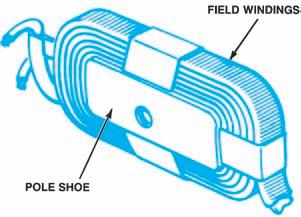
Figure 9-29. Pole shoe and field winding removed from housing.
copper ribbon (Figure 9-29) to increase their current-carrying capacity and electromagnetic field strength. Automotive starter motors usually have four-pole shoes and two to four field windings to provide a strong magnetic field within the motor. Pole shoes that do not have field windings are magnetized by flux lines from the wound poles.
Torque is the force of a starter motor, a force applied in a rotary, or circular direction. The torque, speed, and current draw of a motor arerelated. As speed increases in most automotive starter motors, torque and current draw decrease. These motors develop maximum torque just before the engine begins to turn. Once the engine begins to turn, the motor speed increases and torque decreases. The maximum amount of torque produced by a motor depends upon the strength of its magnetic fields. As field strength increases, torque increases.
DC starter motors (Figure 9-30) work on the principle of magnetic repulsion. This principle states that magnetic repulsion occurs when a straight rod conductor composed of the armature, commutator, and brushes is located in a magnetic field (field windings) and current is flowing through the rod. This situation creates two separate magnetic fields: one produced by the magnet (pole shoes of the magnetic field winding) and another produced by the current flowing through the conductor (armature/commutator/brushes).
Figure 9-30shows the magnet’s magnetic field moving from the N pole to the S pole and the conductor’s magnetic field flowing around the conductor. The magnetic lines of force have a rubber-band characteristic. That is, they stretch and also try to shorten to minimum length.
Figure 9-30shows a stronger magnetic field on one side of the rod conductor (armature/ commutator/brushes) and a weak magnetic field on the other side. Under these conditions, the conductor (armature) will tend to be repulsed by the strong magnetic field (pole shoes and field winding) and move toward the weak magnetic field. As current in the conductor (armature) and the strength of the magnet (field windings) increases, the following happens: • More lines of magnetism are created on the strong side. • More repulsive force is applied to the conductor (armature). • The conductor tries harder to move toward the weak side in an attempt to reach a balanced neutral state. • A greater amount of electrical heat is generated.
NOTE:The combination of the U-shaped conductor loop and the split copper ring are called the commutator because they rotate together.Together they become the armature.
Figure 9-30. Motor principle.
Current flows from the positive ( ) battery terminal through the brush and copper ring nearer the N pole, through the conductor (armature) to the copper ring and brush nearer the S pole and back to the negative ( ) battery terminal. This electrical flow causes the portion of the loop near the S pole to push downward and the N pole to push upward. With a strong field on one side of the conductor and a weak field on the other side, the conductor will move from the strong to the weak. Put another way, the weaker magnetic field between the S and N poles on one side of the conductor is repulsed by the stronger magnetic field on the other side of the conductor. The commutator then rotates. As it turns, the two sides of the conductor loop reverse positions and the two halves of the splitcopper ring alternately make contact with the opposite stationary brushes. This causes the flow direction of electrical current to reverse (alternating current) through the commutator and the commutator to continue to rotate in the same direction.
In order to provide smooth rotation and to make the starter powerful enough to start the engine, many armature commutator segments are used. As one segment rotates past the stationary magnetic field pole, another segment immediately takes its place.
When the starter operates, the current passing through the armature produces a magnetic field in each of its conductors. The reaction between the magnetic field of the armature and the magnetic fields produced by the field coils causes the armature to rotate.
Motor Internal Circuitry
Because field current and armature current flow to the motor through one terminal on the housing, the field and armature windings must be connected in a single complete circuit. The internal circuitry of the motor (the way in which the field and armature windings are connected) gives the motor some general operating characteristics.
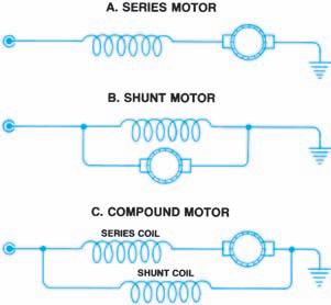
Figure 9-31. Basic motor circuitry.
Figure 9-31shows the three general types of motor internal circuitry, as follows: • Series • Shunt (parallel) • Compound (series-parallel)
All automotive starter motors in use today are the series type or the compound type. The series motor (Figure 9-31A) has only one path for current. As the armature rotates, its conductors cut magnetic flux lines. Acounter-voltage is induced in the armature windings, opposing the original current through them. The countervoltage decreases the total current through both the field and the armature windings, because they are connected in series. This reduction of current also reduces the magnetic field strength and motor torque. Series motors produce a greatamount of torque when they first begin to operate, but torque decreases as the engine begins to turn (Figure 9-32). Series motors work well as automotive starters because cranking an engine requires a great amount of torque at first, and less torque as cranking continues.
The shunt motor (Figure 9-31B) does not follow the increasing-speed/decreasing-torque relationship just described. The counter-voltage within the armature does not affect field current, because field current travels through a separate circuit path. Ashunt motor, in effect, adjusts its torque output to the imposed load and operates at a constant speed. Shunt motors are not used as automotive starters because of their low
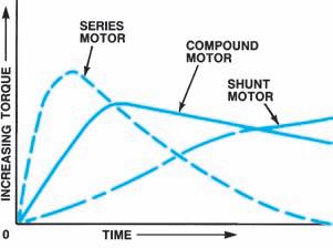
Figure 9-32. Torque output characteristics of series, shunt, and compound motors.
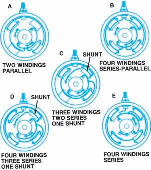
Figure 9-33. Actual relationships of field and armature windings in different types of motors.
initial torque (Figure 9-32), but are used to power other automotive accessories.
The compound motor, shown in Figure9-31C, has both series and shunt field windings. It combines both the good starting torque of the seriestype and the relatively constant operating speed of the shunt-type motor (Figure 9-32). Acompound motor is often used as an automotive starter. Figure9-33shows the actual relationships of field and armature windings in different types of motors.


