
6 minute read
Specific Starting Systems


Figure 9-10. A lever on the steering wheel blocks the movement of the ignition key when the transmission is in gear.

Figure9-11. The clutch pedal must be fully depressed to close the clutch switch and complete the control circuit.
transmissions and transaxles on late-model vehicles. This is an electric switch mounted on the floor or firewall near the clutch pedal. Its contacts are normally open and close only when the clutch pedal is fully depressed (Figure 9-11).
Relays and Solenoids
A magnetic switch in the starting system allows the control circuit to open and close the starter circuit. The switch can be either of the following: • A relay, which uses the electromagnetic field of a coil to attract an armature and close the contact points • A solenoid, which uses the electromagnetic field of a coil to pull a plunger into the coil and close the contact points
In addition to closing the contact points, solenoidequipped circuits often use the movement of the solenoid to engage the starter motor with the engine flywheel. We will explain this in Chapter 10. The terminology used with relays and solenoids is often confusing. Technically, a relay operates with a hinged armature and does only an electrical job; a solenoid operates with a movable plunger and usually does a mechanical job. Sometimes, a solenoid is used only to open and close an electric circuit; the movement of the plunger is not used for any mechanical work. Manufacturers sometimes call these solenoids “starter relays.” Figure 9-12shows a commonly used Ford starter relay. We will continue to use the general term magnetic switch, and will tell you if the manufacturer uses a different name for the device.
For more information about magnetic switches, see the following sections in Chapter 9of the Shop Manual: “Inspection and Diagnosis,” “Starter Control Circuit Devices,” and “Unit Removal.”
Wiring
The starter motor circuit uses heavy-gauge wiring to carry current to the starter motor. The control circuit carries less current and thus uses lightergauge wires.
SPECIFIC STARTING SYSTEMS
Various manufacturers use different starting system components. The following paragraphs briefly describe the circuits used by major manufacturers.
Delco-Remy (Delphi) andBosch
Delco-Remy and Bosch starter motors are used by General Motors. The most commonly used Delco-Remy and Bosch automotive starter motor depends upon the movement of a solenoid both to control current flow in the starter circuit and to engage the starter motor with the engine flywheel. This is called a solenoid-actuated starter. The

Figure 9-12. The Ford starter relay or magnetic switch.
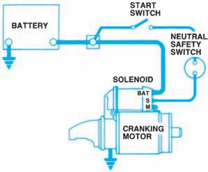
Figure 9-13. GM Starter circuit. (Delphi Automotive
Systems)
solenoid is mounted on, or enclosed with, the motor housing (Figure 9-13).
The type and location of starting safety switches vary within the GM vehicle platforms. Larger-size GM cars use a mechanical blocking device in the steering column (Figure 9-9). The intermediate and smaller cars with automatic transmissions have electrical switches mounted near the shift lever. These are either on the column, as shown in Figure 9-7, or on the floor (Figure 9-6). On front-wheel-drive (FWD) cars with automatic transmissions, the PARK/NEUTRALor PRNDLswitch is an electrical switch mounted on the transaxle case manual lever shaft (Figure 9-14). GM cars with floor-shift manual transmissions use a clutch pedal-operated safety switch. With column-shift manual transmissions, an electric switch is mounted on the column.
Ford Motorcraft
Ford has used three types of starter motors, and therefore has several different starting system circuits. The Motorcraft positive engagement starter has a movable-pole shoe that uses electromagnetism to engage the starter motor with the engine. This motor does not use a solenoid to move anything, but it uses a solenoid to open and close the starter circuit as a magnetic switch (Figure 9-15). Ford calls this solenoid a starter relay.
The Motorcraft solenoid-actuated starter is very similar to the Delco-Remy unit and depends upon the movement of a solenoid to engage the starter motor with the engine. The solenoid is mounted within the motor housing and receives battery current through the same type of starter relay used in the positive engagement system. Although the motor-mounted solenoid could do the job of this additional starter relay, the second relay is installed
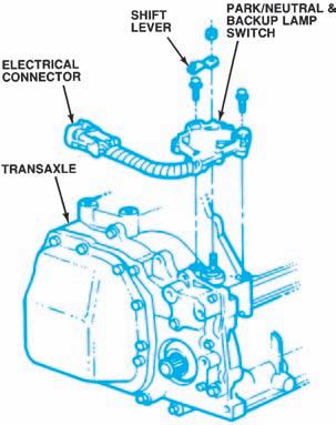
Figure 9-14. GM PRNDL/Park-neutral switch on a GM
Transaxle. (GM Service and Parts Operations)
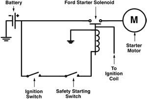
Figure 9-15. The Ford starting system circuit with the positive engagement starter.
on many Ford automobiles to make the cars easier to build. Motorcraft solenoid-actuated starters were used on Ford cars andtrucks with large V8 engines. The Motorcraft permanent magnet gearreduction (PMGR) starter is a solenoid-actuated design that operates much like the Motorcraft solenoid-actuated starter previously described. However, the starter circuit may or may not use a starter relay, depending on the car model.
Rear-wheel-drive (RWD) Ford automobiles with manual transmissions have no starting safety switch. Front-wheel-drive (FWD) models with manual transaxles have a clutch interlock switch. If a Ford car with an automatic transmission has a column-mounted shift lever, a blocking interlock device prevents the ignition key from turning when the transmission is in gear. If the automatic transmission shift lever is mounted on the floor, an electrical switch prevents current from flowing to the starter relay when the transmission is in gear. The switch may be mounted on the transmission case or near the gearshift lever.
DaimlerChrysler
Chrysler uses a solenoid-actuated starter motor. The solenoid is mounted inside the motor housing and receives battery current through a starter relay, as shown in Figure 9-16. Chrysler starter relays used prior to 1977 have four terminals, as shown in Figure 9-17A. In 1977, a second set of contacts and two terminals were added (Figure 9-17B). The extra contacts and terminals allow more current to flow through the relay to the ignition system and to the exhaust gas recirculation (EGR) timer. This has no effect on the operation of the relay within the starting system. These starter relays generally were mounted on the firewall.
Current Chrysler starting systems use a standard five-terminal Bosch relay (Figure 9-18) but only four terminals are used in the circuit (Figure 9-19). The relay is located at the front of the driver’s-side strut tower in a power distribution center or cluster.
Chrysler automobiles with manual transmissions have a clutch interlock switch, as shown in Figure 9-20. Current from the starter relaycan flow to ground only when the clutch pedalis fully depressed. Cars with automatic transmissions have an electrical neutral start switch mounted on the transmission housing (Figure 9-21). When the transmission is out of gear, the switch provides a ground connection for the starter control circuit.
Toyota and Nissan
Toyota and Nissan use a variety of solenoidactuated direct drive and reduction-gear starter designs manufactured primarily by Hitachi and Nippondenso, as shown in Figures 9-22and 9-23. The neutral start switch (called an inhibitor switch by the Japanese automakers) incorporates a relay in its circuit.

Figure 9-16. Typical DaimlerChrysler starting system. (DaimlerChrysler Corporation)

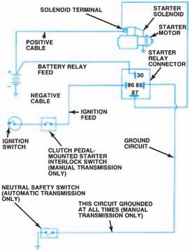
Figure 9-17. Comparison of the terminals on a pre1977 starter relay (A) and a 1977 or later relay (B).
(DaimlerChrysler Corporation) Figure 9-18. DaimlerChrysler starting system with a
five-terminal relay. (DaimlerChrysler Corporation)


