
13 minute read
Differences


STATOR COIL
ROTOR COIL
E B IG
F
P
E Tr1 Tr2
Tr3
IC REGULATOR B
IG
S S IGN.S/W
L L CHARGE LAMP
MONOLITHIC INTEGRATED CIRCUIT
Figure 8-56. When AC generator voltage is too high, the regulator momentarily cuts off current to the rotor coils, eliminating the magnetic field. The rotor continues to spin, but no voltage is generated. (Reprinted by permission of Toyota
Motor Corporation)
battery voltage, it redirects current to switch off the charge lamp.
During normal operation, AC generator voltage exceeds the typically specified 14.5 volts at times. To protect the battery and delicate components in the electrical system, the IC regulator shuts off current to the rotor, cutting AC generator output to zero (Figure 8-58). Note that even though the AC generator is momentarily “turned off,” the charge lamp does not come on. Within a split second, the IC regulator re-energizes the rotor again once output falls below the minimum. The IC regulator switches battery voltage on and off this way to control output and maintain system voltage at an ideal level.
AC GENERATOR (ALTERNATOR) DESIGN DIFFERENCES
Original equipment manufacturers (OEM) use various AC generator designs for specific applications. It has been noted that such factors as maximum current output and field circuit types affect AC generator construction. The following paragraphs describe some commonly used automotive AC generators.
Delphi (Delco-Remy) General Motors Applications
Delphi, formerly the Delco-Remy division of General Motors Corporation, is now a separate corporation that supplies most of the electrical devices used on GM vehicles, as well as those of some other manufacturers. The trademark name for Delco-Remy alternators was Delcotron generators. The alternator model number and current output can be found on a plate attached to, or stamped into, the housing.
DN-Series
The 10-DN series AC generator or alternator uses an external electromagnetic voltage regulator. Six individual diodes are mounted in the rear housing(Figure 8-59) with a capacitor for protection. A14-pole rotor and Y-type stator
STATOR COIL
B IG IG
S S IGN.S/W
ROTOR COIL
E F
P
E TR1 TR2
TR3 L L CHARGE LAMP
IC REGULATOR MONOLITHIC INTEGRATED CIRCUIT
Figure 8-57. When the ignition is on and the engine is not running, the regulator energizes the rotor coil to build a magnetic field in the stator. The regulator turns on the charge light, indicating that the AC generator is not gener-
ating a voltage. (Reprinted by permission of Toyota Motor Corporation)
STATOR COIL
B IG B
IG
S S IGN.S/W
ROTOR COIL
E F
P
E TR1 TR2
TR3 L L CHARGE LAMP
IC REGULATOR MONOLITHIC INTEGRATED CIRCUIT
Figure 8-58. After the engine is running, the AC generator generates a voltage greater than the battery. The
charge light goes out, indicating normal operation. (Reprinted by permission of Toyota Motor Corporation)
Figure 8-59. A 10-SI series AC generator (alternator).
(Delphi Automotive Systems)
provide current output. Field current is drawn from rectified output and travels through a B-circuit. The terminals on a 10-DN are labeled BAT, GRD, R, and F. If the AC generator is used with an external electromagnetic regulator, the following applies:
• BATconnects AC generator output to the insulated terminal of the battery. • GRD, if used, is an additional ground path. • R, if used, is connected to a separate field relay controlling the indicator lamp. • F connects the rotor winding to the voltage regulator.
Some 10-DN alternators are used with a remotely mounted solid-state regulator. The voltage control level of this unit is usually adjustable. The terminal connections are the same for electromagnetic and solid-state regulators.
SI Series
The 10-SI series AC generator uses an internally mounted voltage regulator and came into use in the early 1970s. The most common early model Delcotron alternators are part of the SI series and include models 10, 12, 15, and 27 as shown in Figure 8-60. A14-pole rotor is used in most models. The 10-SI and 12-SI models have Y-type stators, and the 15-SI and 27-SI models have delta-type stators. Two general SI designs have been used, with major differences appearing in the rear housing diode installation, regulator appearance, field circuitry, and ground path.
Most SI models have a rectifier bridge that contains all six rectifying diodes (Figure 8-61). The regulator is a fully enclosed unit attached by screws to the housing. Field current is drawn from unrectified AC generator output and rectified by an additional diode trio. All SI models have A-circuits, their terminals are labeled BAT, No. 1, and No. 2. • The BATterminal connects AC generator output to the insulated terminal of the battery. • The No. 1 terminal conducts battery current to the rotor winding for the excitation circuit and is connected to the indicator lamp. • The No. 2 terminal receives battery voltage so the voltage regulator can react to system operating conditions. All SI models have a capacitor installed in the rear housing to protect the diodes from sudden voltage surges and to filter out voltage ripples that could produce EMI. The 27-SI, which is intendedprincipally for commercial vehicles, has an adjustable voltage regulator (Figure 8-62). The voltage is adjusted by removing the adjustment cap, rotating it until the desired setting of low,

Figure 8-60. A 10-SI series AC generator [Delcotron].
(Delphi Automotive Systems)
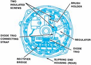
Figure 8-61. The rear end housing of the later-model
10-SI. (Delphi Automotive Systems)
medium, medium-high, or high is opposite the arrow on the housing, and reinstalling it in the new position. Repair or replace a 27-SI AC generator only if it fails to pass an output test after the regulator has been adjusted.
CS Series
The smaller Delco-Remy CS series AC generators introduced on some 1986 GM cars (Figure 8-63) maintain current output similar to larger AC generators. This series includes models CS-121, CS-130, and CS-144. The number following the CS designation denotes the outer diameter of the stator lamination in millimeters. All models use a delta-type stator. Field current is taken directly from the stator, eliminating the field diode trio. Anintegral cooling fan is used on the CS-121 and CS-130.
Electronic connections on CS AC generators include a BAToutput terminal and either a one- or two-wire connector for the regulator. Figure 8-64 shows the two basic circuits for CS AC generators, but there are a number variations. Refer to the vehicle service manual for complete and accurate circuit diagrams. The use of the P, F, and S terminals is optional. • The Pterminal, connected to the stator, may be connected to a tachometer or other such device. • The F terminal connects internally to field positive and may be used as a fault indicator. • The S terminal is externally connected to battery voltage to sense the voltage to be controlled.
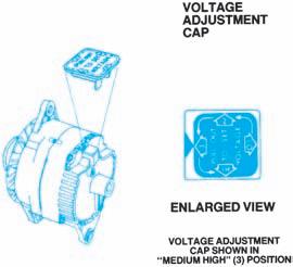
Figure8-62. The Delco 27-SI alternator has an adjustable voltage regulator. (Delphi Automotive Systems)

Figure 8-63. Typical Delco-Remy CS series AC generator (alternator) construction. (Delphi Automotive Systems)

Figure 8-64. Two basic circuits for CS AC generators
(alternator). (Delphi Automotive Systems)
• The Lterminal connects the regulator to the indicator lamp and battery.
The indicator lamp in a CS charging system works differently than in other Delco-Remy systems: Any defect causes it to light at full brilliance. The lamp also lights if charging voltage is either too low or too high. If the regulator has an I terminal, its wire supplies field current in addition to that applied internally, either directly from the switch or through a resistor.
Motorcraft
Motorcraft, a division of Ford Motor Company, makes most of the AC generators used on domestic Ford vehicles. Model and current rating identifications for later models are stamped on the front housing with a color code. Motorcraft AC generators prior to 1985 are used with eitheran electromechanical voltage regulator or a remotely mounted solid-state regulator. One exception to this is the 55-ampere model of 1969–1971, which has a solid-state regulator mounted on the rear housing. This model has an A-circuit; all others are B-circuit. The Motorcraft integral alternator/regulator (IAR) model was introduced on some front-wheel drive Ford models in 1985. This AC generator (alternator) has a solid-state regulator mounted on its rear housing. Some Motorcraft charging systems continue to use an external solid-state regulator with either a rearterminal or side-terminal AC generator. These charging systems are called external voltage regulator (EVR) systems to differentiate them from integral alternator/regulator (IAR) systems.
Integral Alternator/Regulator Models
The Motorcraft IAR AC generators are rated at 40 to 80 amperes. The sealed rectifier assembly is attached to the slipring-end housing. On early models, the connecting terminals (BATand STA) protruded from the side of the AC generator in a plastic housing. Current models use a single pin stator (STA) connector and separate output stud (BAT). The brushes are attached to, and removed with, the regulator. AY-type stator is used with a 12-pole rotor. Some applications have an internal cooling fan.
Turning the ignition on sends voltage to the regulator I terminal through a resistor in the circuit. System voltage is sensed and field current is drawn through the regulator Aterminal until the ignition is turned off, which shuts off the control circuit.
If the vehicle has a heated windshield, output is switched from the battery to the windshield by an output control relay. This allows output voltage to increase above the normal regulated voltage and vary with engine speed. The regulator I circuit limits the increase to 70 volts, which is controlled by the heated windshield module during the approximate four-minute cycle of heated windshield operation. When the cycle times out, the charging system returns to normal operation.
DaimlerChrysler
DaimlerChrysler Corporation manufactured all of the AC generators for its domestic vehicles until the late 1980s, when it phased in Bosch and Nippondenso AC generators for use on all vehicles.
DaimlerChrysler used two alternator designs from 1972 through 1984. The standard-duty alternator, rated from 50 to 65 amperes, is identified by an internal cooling fan and the stator core extension between the housings. The heavy-duty 100-ampere alternator has an external fan and a totally enclosed stator core. Identification also is stamped on a color-coded tag on the housing.
All models have a 12-pole rotor and use a remotely mounted solid-state regulator. The brushes can be replaced from outside the housing. Individual diodes are mounted in positive and negative heat

Figure 8-65. The terminals on a DaimlerChrysler standard-duty AC generator (alternator). (Daimler-
Chrysler Corporation)

sink assemblies, and are protected by a capacitor. The terminals on the standard-duty AC generator are labeled BAT, GRD, and FLD (Figure 8-65). • The BATterminal connects AC generator output to the insulated terminal of the battery. • The GRD terminal is the ground connection. • The FLD terminals connect to the insulated brushes. On the 100-ampere model, the FLD terminal has two separate prongs that fit into a single connector (Figure 8-66). The additional GRD terminal is a ground path.
DaimlerChrysler standard-duty AC generators have a Y-type stator connected to six diodes. Although both brush holders are insulated from the housing, one is indirectly grounded through the negative diode plate, making it a B-circuit. The 100-ampere AC generator has a delta-type stator. Each of the conductors is attached to two positive and two negative diodes. These 12 diodes create additional parallel circuit branches for high-current output.
DaimlerChrysler eliminated the use of a separate voltage regulator on most 1985 and later fuel injected and turbocharged engines by incorporating the regulator function into the powertrain control module (PCM), as shown in Figure 8-67.
The computer-controlled charging system was introduced with the standard DaimlerChrysler AC generator on GLH and Shelby turbo models. All other four-cylinder engines used either a new DaimlerChrysler 40/90-ampere AC generator or a modified Bosch 40/90-ampere or 40/100-ampere model.
The DaimlerChrysler-built AC generator uses a delta-type stator. The regulator circuit is basically the isolated-field type, but field current is controlled by integrated circuitry in thelogic and power modules (Figure 8-68) or the logic and power circuits of the singlemodule engine control computer (SMEC) or single-board engine control computer (SBEC). In addition to sensing system voltage, the logic module or circuit senses battery temperature as indicated by system resistance. The computer then switches field current on and off in a duty
BATTERY OUTPUT TERMINAL
GROUND TERMINAL FIELD TERMINALS
FIELD TERMINAL (VOLT-REG) FIELD TERMINAL (IGNITION SWITCH)
Figure 8-66. The terminals on a 100-amp DaimlerChrysler AC generator (alternator). (DaimlerChrysler
Corporation)

Figure 8-67. Typical DaimlerChrysler computer voltage regulation with DaimlerChrysler 40/90-ampere AC generator (alternator). Circuit connections vary on dif-
ferent models. (DaimlerChrysler Corporation) cycle that regulates charging voltage, as in any other system. The DaimlerChrysler computercontrolled charging system has the following important features:
• It varies charging voltage relative to ambient temperature and the system voltage requirements. • A self-diagnostic program can detect charging system problems and record fault codes in system memory. Some codes will light the POWER LOSS, POWER LIMITED, or
MALFUNCTION INDICATOR lamp on the instrument panel; others will not.
Turning the ignition on causes the logic circuit to check battery temperature to determine the control voltage. Apredriver transistor in the logic module or logic circuit signals a driver translator in the power module or power circuit to turn on the AC generator field current (Figure 8-68). The logic module or logic circuit constantly monitors system voltage and battery temperature and signals the driver in the power module or power circuit when field current adjustment is necessary to keep output voltage within the specified 13.6-to14.8-volt range.
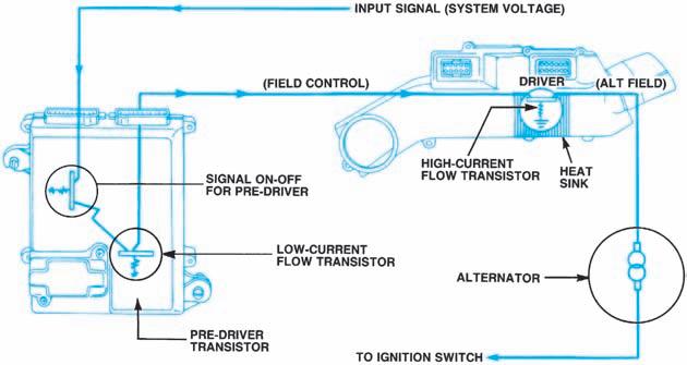
Figure 8-68. DaimlerChrysler computer-regulated charging system internal field control. (DaimlerChrysler Corporation)

Figure 8-69. Current DaimlerChrysler charging sys-
tem. (DaimlerChrysler Corporation)
Bosch AC Generators (Alternators)
Modified Bosch 40/90-ampere and 40/l00-ampere AC generators (alternators) were introduced in 1985 for use with the DaimlerChrysler computercontrolled charging system. These Bosch dualoutput AC generators have a Y-type stator and were modified by removing their internal voltage regulators and changing the external leads. They are fully interchangeable with DaimlerChrysler dual-output AC generators of the same rating. Use of dual-output AC generators was phased out in favor of a single-output Bosch alternator when DaimlerChrysler ceased manufacture of its own alternators in 1989. Current DaimlerChrysler charging systems with a Bosch AC generator (84 or 86 amperes) are essentially the same design as those used with the dual-output AC generators (Figure 8-69). However, an engine controller replaces the separate logic and power modules.
Nippondenso AC Generators
Some current DaimlerChrysler vehicles use Nippondenso AC generators with an output range of 68 to 102 amperes. These are virtual clones of the Bosch design, even to the external wiring connections (Figure 8-70). Charging system circuitry is the same, as are test procedures.

Figure 8-70. Nippondenso and Bosch AC generators used on DaimlerChrysler vehicles have identical
connections. (DaimlerChrysler Corporation)
Import Vehicle Charging Systems
Many European vehicles have Bosch AC generators featuring Y-type stators. Bosch models with a remote regulator use six rectifiers and have a threaded battery terminal and two-way spade connector on the rear housing. Those with an integral regulator contain 12 rectifiers and have a threaded battery stud marked B and a smaller threaded stud marked D . This smaller stud is used for voltage from the ignition switch. Models with internal regulators also have a diode trio to supply field current initially and a blocking diode to prevent current from flowing back to the ignition system when the ignition is turned off.
Several manufacturers such as Hitachi, Nippondenso, and Mitsubishi provide AC generators for Japanese vehicles. While all function on the same principles just studied, the design and construction of some units are unique. For example, Figure 8-71 shows a Mitsubishi AC generator that uses an integral regulator with double Y-stator and 12 diodes in a pair of rectifier assemblies to deliver high current with high voltage at low speeds. Adiode trio internally supplies the field, and a 50-ohm resistor in the regulator performs the same function as the Bosch blocking diode.


