
3 minute read
Charge/Voltage/Current Indicators


Figure8-50. DaimlerChryslercomputer-regulated charging system internal field control. (DaimlerChrysler
Corporation)
10 seconds, it sets a code 16 in memory and turns on the malfunction indicator lamp (MIL).
Diagnostic Trouble Codes (DTC)
On late-model DaimlerChrysler vehicles, the onboard diagnostic capability of the engine control system detects charging system problems and records up to five diagnostic trouble codes (DTC) in the system memory. Some of the codes light a MILon the instrument panel; others do not. Problems in the General Motors CS charging system cause the PCM to turn on the indicator lamp and set a single code in memory.
CHARGE/VOLTAGE/ CURRENT INDICATORS
A charging system failure cripples an automobile. Therefore, most manufacturers provide some way for the driver to monitor the system operation. The indicator may be an ammeter, a voltmeter, or an indicator lamp.

Figure8-51. GM ammeter. (GM Service and Parts Operations)
Ammeter
An instrument panel ammeter measures charging system current into and out of the battery and the rest of the electrical system (Figure 8-51). The ammeter reads the voltage drop of the circuit. When current is traveling from the AC generator into the battery, the ammeter moves in a positive or charge direction. When the battery takes over the electrical system’s load, current travels in the opposite direction and the needlemoves into the negative, or discharge, zone. The ammeter simply indicates which is doing the most work in the electrical system, the battery or the AC generator (alternator). Some ammeters are graduated to indicate the approximate current in amperes, such as 5, 10, or 20. Others simply show an approximate rate of charge or discharge, such as high, medium, or low. Some ammeters have a resistor parallel so the meter does not carry all of the current, these are called shunt ammeters. While the ammeter tells the driver whether the charging system is functioning normally, it does not give a good picture of the battery condition. Even when the ammeter indicates a charge, the current output
may not be high enough to fully charge the battery while supplying other electrical loads.
Voltmeter
The instrument panels of many late-model vehicles contain a voltmeter instead of an ammeter (Figure 8-52). Avoltmeter measures electrical pressure and indicates regulated generator voltage output or battery voltage, whichever is greater. System voltage is applied to the meter through the ignition switch contacts. Figure 8-53 shows a typical voltmeter circuit.
The voltmeter tells a driver more about the condition of the electrical system of a vehicle than an ammeter. When a voltmeter begins to indicate lower-than-normal voltage, it is time to check the battery and the voltage regulator.
Indicator Lamps
Most charging systems use an instrument panel indicator, or warning lamp, to show general charging system operation. Although the lamp usually does not warn the driver of an overcharged battery or high charging voltage, it lights to show an undercharged battery or low voltage from the AC generator.
The lamp also lights when the battery supplies field current before the engine starts. The lamp is often connected parallel to a resistor; therefore, field current travels even if the bulb fails. The lamp is wired so it lights when battery current travels through it to the AC generator field. When the alternator begins to produce voltage, this voltage is applied to the side of the lamp away from the battery. When the two voltages are equal, no voltage drops are present across the lamp and it goes out. When indicator lamps are used, the regulator must be able to monitor when the AC generator is charging. One method is to use “stator” or neutral voltage. This signal is present only when the AC generator is charging, and is onehalf of charging voltage. When stator voltage is about three volts, it energizes a relay to open the indicator lamp ground circuit (Figure 8-53).
Figure 8-54shows a typical warning lamp circuit installation. In figure 9-14, a 500-ohm resistor is used for warning lamp systems and a 420ohm resistor for electronic display clusters. In Figure 8-54, a 40-ohm resistor (R5) is installed near the integral regulator. In each case, the grounded path ensures the warning lamp lights if an open occurs in the field circuitry.
As previously discussed, indicator lamps can also be controlled by the field relay. The indicator lamp for a Delco-Remy CS system works differently than most others. It lights if charging voltage is either too low or too high. Any problem in the charging system causes the lamp to light at full brilliance.
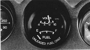
Figure 8-52. Automotive voltmeter in instrument panel.
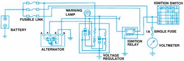
Figure 8-53. A typical voltmeter circuit.


