9 minute read
Solid-state Regulators


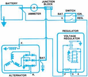
ACgenerators are double-contact units (Figure 8-40). When the first set of contacts opens at lower rotor speeds, current passes through a resistor wired in series with the field circuit. These contacts are called the series contacts. The value of the regulating resistor is kept very low to permit high field current when needed. At higher rotor speeds, the coil further attracts the armature and a second set of contacts is closed. This grounds the field circuit, stopping the field current. These contacts are called the shorting contacts because they short-circuit the field to ground. The double-contact design offers consistent regulation over a broad range of AC generator speeds.
Figure 8-40. The circuit diagram of a double-contact
regulator. (Delphi Automotive Systems)
Solid-state regulators completely replaced the older electromagnetic design on late-model vehicles. They are compact, have no moving parts, and are not seriously affected by temperature changes. The early solid-state designs combine transistors with the electromagnetic field relay. The latest and most compact is the integrated circuit (IC) regulator (Figure 8-41). This combines all control circuitry and components on a single
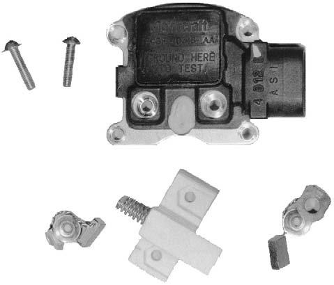
Figure 8-41. An example of the latest integrated circuit regulator design, a Ford IAR regulator and brush holder.
silicon chip. Attaching terminals are added and the chip is sealed in a small plastic module that mounts inside, or on the back of, the AC generator. Because of their construction, however, all solid-state regulators are non-serviceable and must be replaced if defective. No adjustments are possible.
Here is a review of most components of a solid-state regulator: • Diodes • Transistors • Zener diodes • Thermistors • Capacitors
Diodes are one-way electrical check valves. Transistors act as relays. AZener diode is specially doped to act as a one-way, electrical check valve until a specific reverse voltage level is reached. At that point, the Zener diode allows reverse current to pass through it.
The electrical resistance of a thermistor, or thermal resistor, changes as temperature changes. Most resistors used in automotive applications are called negative temperature coefficient (NTC) resistors because their resistance decreases as temperature increases. The thermistor in a solid-state regulator reacts to temperature to ensure proper battery charging voltage. Some manufacturers, in order to smooth out any abrupt voltage surges and protect the regulator from damage, use a capacitor. Diodes may also be used as circuit protection.
General Regulator Operation
Figure 8-42is a simplified circuit diagram of a solid-state regulator. This A-circuit regulator is contained within the housing. Terminal 2 on the AC generator is always connected to the battery, but battery discharge is limited by the high resistance of R2 and R3. The circuit allows the regulator to sense battery voltage.
When the ignition switch is closed in the circuit shown in Figure 8-43, current travels from the battery to ground through the base of the TR1 transistor. This causes the transistor to conduct current through its emitter-collector circuit from the battery to the low-resistance rotor winding, which energizes the AC generator field and turns on the warning lamp. When the AC generator begins to produce current (Figure 8-44), field current is drawn from unrectified AC generator output andrectified by the diode trio, which is charging voltage. The warning lamp is turned off by equal voltage on both sides of the lamp.
When the AC generator has charged the battery to a maximum safe voltage level (Figure 8-45), the battery voltage between R2 and R3 is high enough to cause Zener diode D2 to conduct in reverse bias. This turns on TR2, which shorts the base circuit of TR1 to ground. When TR1 is turned off, the field circuit is turned off at the ground control of TR1.
With TR1 off, the field current decreases and system voltage drops. When voltage drops low enough, the Zener diode switches off and current is no longer applied to TR2. This opens the field circuit ground and energizes TR1. TR1 turns back on. The field current and system voltage increase. This cycle repeats many times per second to limit the AC generator voltage to a predetermined value.
The other components within the regulator perform various functions. Capacitor C1 provides
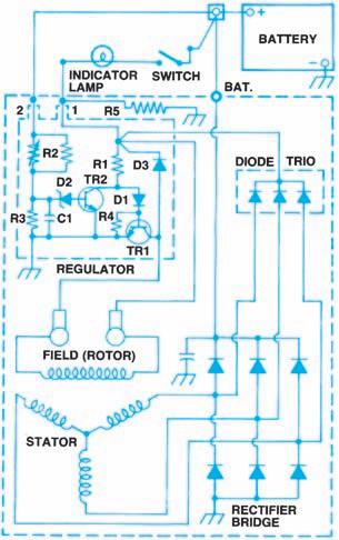
Figure 8-42. Circuit diagram of a typical solid-state
voltage regulator. (Delphi Automotive Systems)
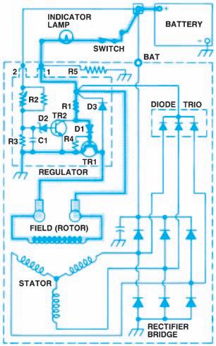
Figure 8-43. Field current in a typical solid-state reg-
ulator during starting. (Delphi Automotive Systems)
stable voltage across resistor R3. Resistor R4 prevents excessive current through TR1 at high temperatures. To prevent circuit damage, diode D3 bypasses high voltages induced in the field windings when TR1 turns off. Resistor R2 is a thermistor, which causes the regulated voltage to vary with temperature. R5 allows the indicator lamp to turn off if the field circuit is open.
For more information about voltage regulators, see the “Voltage Regulator Service Section” in Chapter 8 of the Shop Manual.
Specific Solid-State Regulator Designs
GM Delco-Remy (Delphi)
The Delco-Remy solid-state automotive regulator is used in Figures 8-43to 8-46to explain the basic operation of these units. This is the integral regulator unit of the SI series AC generators. The 1 and 2 terminals on the housing connect directly to the regulator. The 1 terminal conducts field current from the battery or the AC Generator (alternator) and controls the indicator lamp. The 2 terminal receives battery voltage and allows the Zener diode to react to it.
Unlike other voltage regulators, the multifunction IC regulator used with Delco-Remy CS-series AC generators (Figure 8-46) switches the field current on and off at a fixed frequency of 400 Hz (400 times per second). The regulator varies the duty cycle, or percentage of on time to total cycle time, to control the average field current and to regulate voltage. At high speeds, the on time might be 10 percent with the off time 90 percent. At low speeds with high electrical loads, this ratio could be reversed: 90 percent on time and 10 percent off time. Unlike the SI series, CS AC generators have
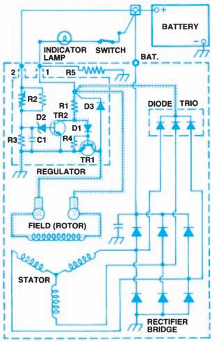
Figure 8-44. Field current drawn from AC generator
(alternator) output. (Delphi Automotive Systems)
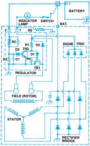
Figure 8-45. When AC generator (alternator) output voltage reaches a maximum safe level, no current is allowed in the rotor winding. (Delphi Automotive Systems)
no test hole to ground the regulator for full-field testing. The regulator cannot be tested with an ohmmeter; a special tester is required.
Motorcraft
At one time, Motorcraft AC generators used both remote-mounted and integral solid-state regulators. Motorcraft regulator terminals are designated as follows: • A or A connects the battery to the field relay contacts. • S connects the AC generator output to the field relay coil. • F connects the field coil to the regulator transistors. • I connects the ignition switch to the field relay and regulator contacts (only on vehicles with a warning lamp). Ford began using a remote-mounted, fully solidstate regulator on its intermediate and large models in 1978. The functions of the I, A , 8, and F terminals are identical to those of the transistorized regulator. On systems with an ammeter, the regulator is color coded blue or gray, and the T terminal is not used. On warning lamp systems, the regulator is black, and all terminals can be used. The two models are not interchangeable, and cannot be substituted for the earlier solidstate unit with a relay or for an electromagnetic regulator. However, Ford does provide red or clear service replacement solid-state regulators, which can be used with both systems.
The Motorcraft integral alternator/regulator (JAR) introduced in 1985 uses an IC regulator, which is also mounted on the outside of the rear housing. This regulator differs from others because it contains a circuit indicating when the battery is being overcharged. It turns on the charge indicator lamp if terminal Avoltage is too high or too low, or if the terminal 8 voltage signal is abnormal.
DaimlerChrysler
The DaimlerChrysler solid-state regulator depends on a remotely mounted field relay to open and close the isolated field or the A-circuit AC generator field. The relay closes the circuit only when the ignition switch is turned on. The voltage regulator (Figure 8-47) contains two transistors that are turned on and off by a Zener diode. The Zener diode reacts to system voltage to start and stop field
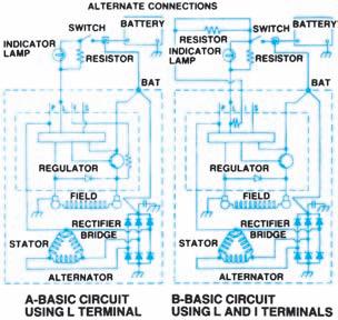
Figure 8-46. GM CS AC generator (alternator) regu-
lator circuit. (Delphi Automotive Systems)
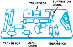
Figure 8-47. DaimlerChrysler solid-state voltage reg-
ulator. (DaimlerChrysler Corporation)
current. The field current travels through what DaimlerChrysler calls a field-suppression diode, which limits current to control AC generator output. The regulator also contains a thermistor to control battery charging voltage at various temperatures. The regulator has two terminals: One is connected to the ignition system; the other is connected to the alternator field.
Computer-Controlled Regulation
DaimlerChrysler Corporation eliminated the separate regulator by moving its function to the powertrain control module (PCM) in 1985. When the ignition is turned on, the PCM logic module or logic circuit checks battery temperature to determine the control voltage (Figure 8-48). Apre-driver transistor in the logic module or logic circuit then signals the power module or power circuit driver transistor to turn the AC generator current on (Figure 8-49). The logic module or logic circuit continually monitors battery temperature and system voltage. At the same time, it transmits output signals to the power module or power circuit driver to adjust the field current as required to maintain output between 13.6 and 14.8 volts. Figure 8-50shows the complete circuitry involved.
General Motors has taken a different approach to regulating CS charging system voltage electronically. Turning the ignition switch on supplies voltage to activate a solid-state digital regulator, which uses pulse-width modulation (PWM) to supply rotor current and thus control output voltage. The rotor current is proportional to the PWM pulses from the digital regulator. With the ignition on, narrow width pulses are sent to the rotor, creating a weak magnetic field. As the engine starts, the regulator senses AC generator rotation through AC voltage detected on an internal wire. Once the engine is running, the regulator switches the field current on and off at a fixed frequency of about 400 cycles per second (400 Hz). By changing the pulse width, or on-off time, of each cycle, the regulator provides a correct average field current for proper system voltage control.
A lamp driver in the digital regulator controls the indicator warning lamp, turning on the bulb when it detects an under- or over-voltage condition. The warning lamp also illuminates if the AC generator is not rotating. The PCM does not directly control charging system voltage, as in the DaimlerChrysler application. However, it does monitor battery and system voltage through an ignition switch circuit. If the PCM reads a voltage above 17 volts, or less than 9 volts for longer than
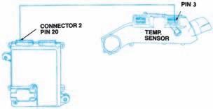
Figure 8-48. DaimlerChrysler solid-state voltage reg-
ulator. (DaimlerChrysler Corporation)
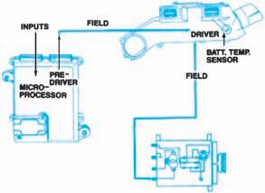
Figure8-49. Battery temperature circuit of the DaimlerChrysler computer regulated charging system. (Daimler-
Chrysler Corporation)


