
9 minute read
Current Production in an AC Generator


For more information about generator maintenance, see the section on “Disassembly, Cleaning, and Inspection” in Chapter 8 of the Shop Manual.
Diode Installation
Automotive AC generators that have three stator windings generally use six diodes to rectify the current output. The connections between the conductors and the diodes vary slightly, but each conductor is connected to one positive and one negative diode, as shown in Figure 8-20.
The three positive diodes are always insulated from the AC generator housing. They are connected to the insulated terminal of the battery and to the rest of the automotive electrical system. The battery cannot discharge through this connection because the bias of the diodes blocks any current from the battery. The positive diodes only conduct current traveling from the conductors toward the battery.
The positive diodes are mounted together on a conductor called a heat sink (Figure 8-21). The heat sink carries heat away from the diodes, just as the radiator carries heat away from the engine. Too much heat damages the diodes.
In the past, the three negative diodes were pressed or threaded into the AC generator rear housing. On high-output AC generators, they may be mounted in a heat sink for added protection. Ineither case, the connection to the AC generator housing is a ground path; the negative diodes conduct only the current traveling from ground into the conductors. Each group of three or more negative or positive diodes can be called a diode bridge, a diode trio, or a diode plate. Some manufacturers use complete rectifier assemblies containing all the diodes and connections on a printed circuit board. This assembly is replaced as a unit if any of the individual components fail.
Each stator winding connects to its proper negative diode through a circuit in the rectifier. A capacitor generally is installed between the output terminal at the positive diode heat sink to ground at the negative diode heat sink. This capacitor is used to eliminate voltage-switching transients at the stator, to smooth out the AC voltage fluctuations, and to reduce electromagnetic interference (EMI).
Figure 8-20. Each conductor is attached to one positive and one negative diode. Figure 8-21. Positive and negative diodes may be mounted in a heat sink for protection.
CURRENT PRODUCTION IN ANAC GENERATOR
After studying the principles of AC generator operation and its components, the total picture of how an automotive AC generator produces current becomes clear.
Three-Phase Current
The AC generator stator has three windings. Each is formed into a number of coils, which are spaced evenly around the stator core. The voltages induced across each winding by one rotor revolution are shown in the graphs of Figure 8-22. The

Figure 8-22. The single-phase voltages of three conductors create a three-phase voltage output. (Reprinted
by permission of Robert Bosch GmbH)
total voltage output of the AC generator is three overlapping, evenly spaced, single-phase voltage waves, as shown in the bottom graph of the illustration. If the stator windings are connected into a complete circuit, the three-phase voltages cause an AC output called three-phase current.

Figure 8-23. Two types of stator windings. (Daimler-
Chrysler Corporation)
Stator Types
When the three conductors are completely wound on the stator core, six loose ends remain. The way in which these ends are connected to the diode rectifier circuitry determines if the stator is a Y-type or a Delta-type (Figure 8-23). Both kinds of stators produce three-phase current and the rectification produces DC output. However, the voltage and current levels within the stators differ.
Y-Type Stator Design
In the Y-type stator or Y-connected stator, one end of each of the three windings is connected at a neutral junction (Figure 8-23). The circuit diagram of the Y-type stator (Figure 8-24) looks like the letter Y. This is also sometimes called a wye or a star connection. The free end of each conductor is connected to a positive and a negative diode.
In a Y-type stator (Figure 8-24), two windings always form a series circuit between a positive and a negative diode. At any given instant, the position of the rotor determines the direction of current through these two windings. Current flows from the negative voltage to the positive voltage. Acomplete circuit from ground, through a negative diode, through two of the windings, and through a positive diode to the AC generator output terminal, exists throughout the 360-degree rotation of the rotor. The induced voltages across the two windings added together produce the total voltage at the output terminal. The majority of AC generators in use today have Y-type stators because of the need for high voltage output at low speeds.

Figure 8-24. Y-type stator circuit diagram. (Daimler-
Chrysler Corporation)
Unrectified AC Generators Although the battery cannot be recharged withAC, other automotive accessories can be designed to run on unrectified alternator output. Motorola has made AC generators with separate terminals for AC output.Ford has offered a front-and-rear-window defroster that heats the windows with three-phase, 120-volt AC. An additional AC generator supplies the highvoltage current.This second AC generator is mounted above the standard 12-volt AC generator and driven by the same belt.
The Ford high-voltage AC generator has a Y-type stator.Field current draw is more than 4 amps, and there is no regulator in the field circuit.Output is 2,200 watts at high engine speed. All of the wiring between the AC generator and the defrosters is special, shielded wiring with warning tags at all connectors.Ford test procedures use only an ohmmeter, because trying to test such high output could be dangerous.
Some AC generators include a center tap lead from the neutral junction to an insulated terminal on the housing (Figure 8-25). The center tap may control the field current, to activate an indicator lamp, to control the electric choke on a carburetor, or for other functions.
Delta-Type Stator Design
The delta-type stator or delta-connected stator has the three windings connected end-to-end (Figure 8-26). The circuit diagram of a delta-type stator (Figure 8-26) looks like the Greek letter delta ( ), a triangle. There is no neutral junction in a delta-type stator. The windings always form two parallel circuit paths between one negative and two positive diodes. Current travels through two different circuit paths between the diodes (Figure 8-27). The current-carrying capacity of the stator is double because there are two parallel circuit paths. Deltatype stators are used when a high current output is needed.
NEUTRAL JUNCTION CENTER TAP (SOME)
STATOR CONNECTION (1 OF 3)
Figure 8-25. A Y-type stator circuit diagram. The center tap connects to the neutral junction of the Y-type stator of
some AC generators. (DaimlerChrysler Corporation)

Figure 8-26. Circuit diagram of a delta-type stator.
Phase Rectification
The current pattern during rectification is similar in any automotive AC generator. The only differences are specific current paths through Y-type and deltatype stators as shown in Figures 8-27and 8-28.
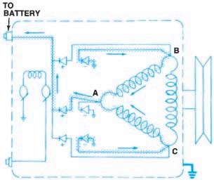
Figure 8-27. A typical current path during rectifica-
tion in a delta-type stator. (DaimlerChrysler Corporation)
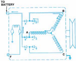
Figure 8-28. A typical current path during rectifica-
tion in a Y-type stator. (DaimlerChrysler Corporation)
Rectification with Multiple-Pole Rotors
The three-phase voltage output used in the examples (Figure 8-29) is the voltage, which would result if the rotor had only one N and one S pole. Actual AC generator rotors have many N and S poles. Each of these N-S pairs produces one complete voltage sine wave per rotor revolution, across each of the three windings. One complete sine wave begins at zero volts, climbs to a positive, peak, drops past zero to a negative peak, then returns to zero, or baseline voltage. In Figure 8-30, the sine wave voltage caused by a single pole is shown as a dashed line. The actual voltage trace from one winding of a 12-pole AC generator is shown as a solid line. The entire stator output is three of these waves, evenly spaced and overlapping (Figure 8-31). The maximum voltage value from these waves pushes current through the diodes (Figure 8-32).
After rectification, AC generator (alternator) output is DC voltage, which is slightly lower than the maximum voltage peaks of the stator output. The positive portion of the AC sine wave greater than the DC output voltage is viewable on an oscilloscope in what is called an AC generator (alternator) ripple pattern (Figure 8-33).

Figure 8-29. The three-phase voltage from one revo-
lution of the rotor. (Reprinted by permission of Robert Bosch GmbH)
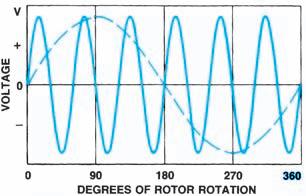
Figure 8-30. An AC generator (alternator) with six pairs of N-S poles would produce the solid line voltage trace. The dashed line represents an alternator
with one pair. (Reprinted by permission of Robert Bosch GmbH)
Excitation Field Circuit
Field current through the rotor windings creates the magnetic field of the rotor. Field current is drawn from the AC generator output circuit once

Figure 8-31. This is the total output of a three-winding, multiple-pole AC generator.

Figure 8-33. AC generator (alternator) ripple is the AC voltage exceeding DC output voltage.
the AC generator has begun to produce current. However, there is not enough residual magnetism in the rotor poles to induce voltage during start up. An AC generator cannot start operation independently. Field current must be drawn from another source in order to magnetize the rotor and begin AC generator output.
The other source is the vehicle battery connected to the rotor winding through the excitation, or field, circuit. Battery voltage “excites” the rotor magnetic field and begins output. When the engine is off, the battery must be disconnected from the excitation circuit. If not, it could discharge through the rotor windings to ground. Some AC generators use a relay to control this circuit. Other systems use the voltage regulator or a part of the ignition switch to control the excitation circuit.
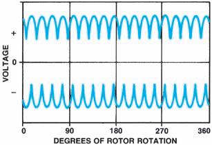
Figure 8-32. The diodes receive the maximum voltage values.

Figure 8-34. Some AC generators (alternators) have additional diodes to rectify field current. (Reprinted by
permission of Robert Bosch GmbH)
Once the AC generator has started to produce current, field current is drawn from the AC generator output. The current may be drawn after it has been rectified by the output diodes. Some AC generators draw field current from unrectified AC output, which is then rectified by three additional diodes to provide DC to the rotor winding (Figure 8-34). These additional diodes are called the exciter diodes or the field diodes.
Circuit Types
AC generators (alternators) are designed with different types of field circuits. The two most common types are A-circuits and B-circuits.Circuit types are determined by where the voltage regulator is connected and from where the field current is drawn.


