3 minute read
Diode Rectification


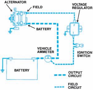
Figure 8-4. The output circuit and the field circuit make up the automotive charging system. (DaimlerChrysler
Corporation)

Figure 8-5. No current flows when the rotor’s magnetic field is parallel to the stator. (DaimlerChrysler Corporation)
current output. Figure 8-6shows the voltage levels induced across the upper half of the looped conductor during one revolution of the rotor.
The constant change of voltage, first to a positive peak and then to a negative peak, produces a sine wave voltage. This name comes from the trigonometric sine function. The wave shape is controlled by the angle between the magnet and the conductor. The sine wave voltage induced across one conductor by one rotor revolution is called a single-phase voltage. Positions 1 through 5 of Figure 8-6show complete sine wave singlephase voltage.
This single-phase voltage causes alternating current to flow in a complete circuit because the voltage switches from positive to negative as the rotor

Figure8-6. These are the voltage levels induced across the upper half of the conductor during one rotor
revolution. (DaimlerChrysler Corporation)
turns. The alternating current caused by a singlephase voltage is called single-phase current.
If the single-phase voltage shown in Figure 8-6 made current travel through a simple circuit, the current would flow first in one direction and then in the opposite direction. As long as the rotor turned, the current would reverse its flow with every half revolution. The battery cannot be recharged with alternating current. Alternating current must be rectified to direct current to recharge the battery. This is done with diodes.
A diode acts as a one-way electrical valve. If a diode is inserted into a simple circuit, as shown in Figure 8-7, one-half of the AC voltage is blocked. That is, the diode allows current to flow from X to Y, as shown in position A. In position B, the current cannot flow from Y to X because it is blocked by the diode. The graph in Figure 8-7shows the total current.
The first half of the current, from X to Y, was allowed to pass through the diode. It is shown on the graph as curve XY. The second half of the current, from Y to X, was not allowed to pass through the diode. It does not appear on the graph because it never traveled through the circuit. When the

Figure 8-7. A single diode in the circuit results in half-
wave rectification. (Delphi Automotive Systems) voltage reverses at the start of the next rotor revolution, the current is again allowed through the diode from X to Y.
An AC generator with only one conductor and one diode would show this current output pattern. However, this output would not be very useful because half of the time there is no current available. This is called half-wave rectification, since only half of the AC voltage produced by the AC generator is allowed to flow as DC voltage.
Adding more diodes to the circuit, as shown in Figure 8-8, allows more of the AC voltage to be rectified to DC. In position A, current moves from X to Y. It travels from X, through diode 2, through the load, through diode 3, and back to Y. In position B, current moves from Y to X. It travels from Y, through diode 4, through the load, through diode I, and back to X.
Notice that in both cases current traveled through the load in the same direction. This is because the AC has been rectified to DC. The graph in Figure 8-8shows the current output of an AC generator with one conductor and four diodes.
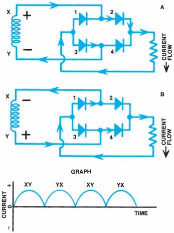
Figure 8-8. More diodes are needed in the circuit for full-wave


