
7 minute read
AC Generator (Alternator) Components


There is more current available because all of the voltage has been rectified. This is called full-wave rectification. However, there are still moments when current is at zero. Most automotive AC generators use three conductors and six diodes to produce overlapping current waves so that current output is never at zero.
Heat Sinks The term heat sink is commonly used to describe the block of aluminum or other material in which the AC generator diodes are mounted.The job of the heat sink is to absorb and carry away the heat in the diodes caused by electricalcurrent through them.This action keeps the diodes cool and prevents damage.An internal combustion engine is also a heat sink.The engine is designed so that the combustion and friction heat are carried away and dissipated to the atmosphere.Although they are not thought of as heat sinks, many individual parts of an automobile—such as the brake drums—are also designed to do this important job.
The previous illustrations have shown the principles of AC generator operation. To provide enough direct current for an automobile, AC generators must have a more complex design. But no matter how the design varies, the principles of operation remain the same.
The design of the AC generator limits its maximum output. To change this maximum value for different applications, manufacturers change the design of the stator, rotor, and other components. The following paragraphs describe the major parts of an automotive AC generator.
Rotor
The rotor carries the magnetic field. Unlike a DC generator, which usually has only two magnetic poles, the AC generator rotor has several north (N) and south (S) poles. This increases the number of flux lines within the AC generator and increases the voltage output. A typical automotive rotor (Figure8-9) has 12 poles: 6 N and 6 S. The rotor consists of two steel rotor halves, or pole pieces, with fingers that interlace. These fingers are the poles. Each pole piece has either all N or all S poles. The magnetic flux lines travel between adjacent N and S poles (Figure 8-10). Keep in mind that an alternator is an AC generator; in some European manufacturers’service manuals, the AC generator (alternator) is referred to as a generator.
Along the outside of the rotor, note that the flux lines point first in one direction and then in the other. This means as the rotor spins inside the AC generator, the fixed conductors are being cut by flux lines, which point in alternating directions. The induced voltage alternates, just as in the example of a simple AC generator with only two poles. Automotive AC generators may have any number of poles, as long as they areplaced N-S-N-S. Common designs use eight to fourteen poles.
The rotor poles may retain some magnetism when the AC generator is not in operation, but this
Figure 8-9. Rotor. (DaimlerChrysler Corporation)
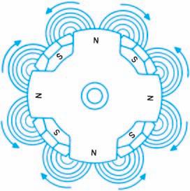
Figure 8-10. The flux lines surrounding an 8-pole
rotor. (DaimlerChrysler Corporation)
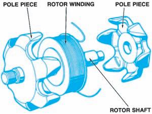
Figure 8-11. The magnetic field of the rotor is created by current through the rotor winding. (Reprinted by
permission of Robert Bosch GmbH)
residual magnetism is not strong enough to induce any voltage across the conductors. Current produces the magnetic field of the rotor through the rotor winding, which is a coil of wire between thetwo pole pieces (Figure 8-11). This is also called the excitation winding, or the field winding. Varying the amount of field current through the rotor winding varies the strength of the magnetic field, which affects the voltage output of the AC generator. Asoft iron core is mounted inside the rotor-winding (Figure 8-12). One pole piece is attached to either end of the core; when field current travels through the winding, the iron core is magnetized, and the pole pieces take on the magnetic polarity of the endof the core to which they are attached. Current is supplied to the winding through
sliprings and brushes.
The combination of a soft iron rotor core and steel rotor halves provides better localization and permeability of the magnetic field. The rotor pole pieces, winding, core, and sliprings are pressed onto a shaft. The ends of this shaft are supported by bearings in the AC generator housing. Outside the housing, a drive pulley is attached to the shaft, as shown in Figure 8-13. Abelt, driven by the engine crankshaft-pulley, passes around the drive pulley to turn the AC generator shaft and rotor assembly.
Stator
The three AC generator conductors are wound onto a cylindrical, laminated core. The lamination prevents unwanted eddy currents from forming in the core. The assembled piece is called a stator (Figure 8-14). The word stator comes from the word “stationary” because it does not rotate, as does the commutator conductor of a DC generator. Each conductor, called a stator winding, is formed into a number of coils spaced evenly around the core. There are as many coil conductors as there are pairs of N-S rotor poles. Figure 8-15shows an incomplete stator with only one of its conductors installed: There are seven coils in the conductor, so the matching rotor would have seven pairs of N-S poles, for a total of fourteen poles. There are two ways to connect the three-stator windings.
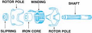
Figure 8-12. Exploded view of the parts of the com-
plete rotor assembly. (DaimlerChrysler Corporation)

Figure 8-13. AC generator (alternator) and drive pul-
ley. (DaimlerChrysler Corporation)
Housing
The AC generator housing, or frame, is made of two pieces of cast aluminum (Figure 8-16). Aluminum is lightweight and non-magnetic and conducts heat well. One housing piece holds a bearing for the end of the rotor shaft where the
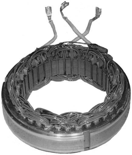
Figure 8-14. An AC generator (alternator) stator.
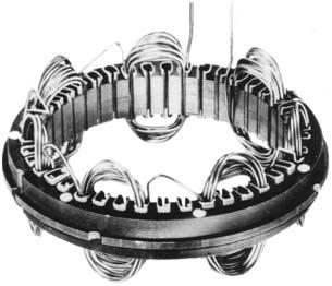
Figure 8-15. A stator with only one conductor installed.
(Delphi Automotive Systems) Figure8-16. AC generator (alternator) housing encloses the rotor and stator.
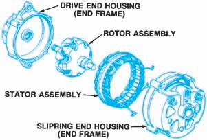

Figure 8-17. AC generator (alternator) with exposed stator core. Figure 8-18. AC generator (alternator) with the stator core enclosed.
drive pulley is mounted. This is often called the drive-end housing, or front housing, of the AC generator. The other end holds the diodes, the brushes, and the electrical terminal connections. It also holds a bearing for the slipring end of the rotor shaft. This is often called the slipring-end housing, or rear housing. Together, the two pieces completely enclose the rotor and the stator windings.
The end housings are bolted together. Some stator cores have an extended rim that is held between the two housings (Figure 8-17). Other stator cores provide holes for the housing bolts, but do not extend to the outside of the housings (Figure 8-18). In both designs, the stator is rigidly bolted in place inside the AC generator housing. The housing is part of the electrical ground path because it is bolted directly to the engine. Anything connected to the housing that is not insulated from the housing is grounded.
Sliprings and Brushes
The sliprings and brushes conduct current to the rotor winding. Most automotive AC generators have two sliprings mounted on the rotor shaft. The sliprings are insulated from the shaft and from each other. One end of the rotor winding is connected to each slipring (Figure 8-19). One brush rides on each ring to carry current to and from the winding. Abrush holder supports each brush and a spring applies force to keep the brush in constant contact with the rotating slipring. The brushes are connected parallel with the AC generator output circuit. They draw some of the AC generator current output and route it through the rotor winding. Current through the winding must be DC. Field current in an AC generator is usually about 1.5 to 3.0 amperes. Because the brushes carry so little current, they do not require as much maintenance as DC generator brushes, which must conduct all of the current output.
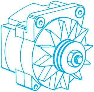
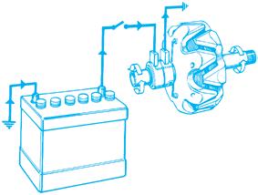
Figure 8-19. The sliprings and brushes carry current to the rotor windings.


