2 minute read
Wire Color Coding


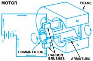
This is done with a split-ring commutator, which rotates with the conductor as shown in Figure 6-37. Current is carried to the conductor through carbon brushes. At the point where current direction must be reversed, the commutator has rotated so that the opposite half of the split ring is in contact with the current-feeding brush. Current flow is reversed in the conductor and rotation continues in the original direction. In actual motors, many more conductor loops are mounted on an armature (Figure 6-38).
Electric motors can be manufactured with several brushes and varying combinations of series and parallel connections for armature windings and electromagnetic field windings. The design depends upon the use to which the motor will be put. Electric motors generally use electromagnetic field poles because they can produce a strong field in a limited space. Field strength in such a motor is determined by the current flow through the field windings. The starter motor is the most common automotive application of this design.
Most small motors used in automotive applications, however, are built with permanent magnet fields. These motors are inexpensive, lightweight, can reverse direction of operation if necessary, and can be equipped with up to three operating speeds. They are ideal for constant light loads, such as a small electric fan.
Regardless of how they are built, all motors work on these principles. Understanding the internal connections of a motor is essential for testing and repair. Figure 6-39shows the circuit symbol for a motor.
Figure 6-37. A simple motor.

Figure 6-40shows current flows through a simple circuit consisting of a 12-volt battery for power, a fuse for protection, a switch for control, and a lamp as the load. In this example, each component is labeled and the direction of current is marked. Manufacturers use color coding to help technicians follow wires in a circuit. We have explained how most automotive wires are covered with a colored polyvinyl chloride (PVC), or plastic, insulation. The color of the insulation helps identify a particular wire in the system. Some drawings of a circuit have letters and numbers printed near each wire (Figure 6-41). The code table accompanying the drawing

Figure 6-39. The electrical symbol for a motor.


Figure 6-41. A Chrysler diagram showing circuits identified by number and wire color. (DaimlerChrysler
Corporation)


