8 minute read
Multiplex Circuits


insulation, made by wrapping cotton or silk around wire and then coating it with rubber, was easily hardened by heat.The insulation often broke off, leaving bare wire exposed.
A common problem in cars that used dry-cell batteries was moisture penetration through the battery’s paper insulation.Current design would flow to ground and the batteries would become discharged.
Even washing a car sometimes caused trouble. Water got into the distributor terminals and made the engine hard to start.Some technicians poured melted wax into the space between the plug wires and the distributor cap terminals. For protection from heat, moisture, oil, and grease, wiring was often run through a metal conduit.Armored cable-insulated wire enclosed in a permanent, flexible metal wrapping was also used, especially in a circuit where any voltage drop was critical.
This is an important point to remember. It may be helpful at this time to review the explanations in Chapters 3and 5of voltage drops and current flow in various circuits from the source, through all the loads, and back to the source. Every electrical load is attached to the chassis so that current can pass through the ground and back to the grounded battery terminal. Grounding connections must be secure for the circuit to be complete. In older cars where plastics were rarely used, most loads had a direct connection to a metal ground. With the increased use of various plastics, designers have had to add a ground wire from some loads to the nearer metal ground. The ground wires in most circuits are black for easy recognition.
The use of multiplexing, or multiplex circuits, is becoming a necessity in late-model automobiles because of the increasing number of conventional electrical circuits required by electronic control systems. Wiring harnesses used on such vehicles have ballooned in size to 60 or more wires in a single harness, with the use of several harnesses in a vehicle not uncommon. Simply put, there are too many wires and too limited space in which to run them for convenient service. With so many wires in close proximity, they are subject to electromagnetic interference (EMI), which you learned about in Chapter 4. To meet the almost endless need for electrical circuitry in the growing and complex design of automotive control systems, engineers are gradually reducing the size and number of wire and wiring harnesses by using a multiplex wiring system.
The term multiplexing means different things to different people, but generally it is defined as a means of sending two or more messages simultaneously over the same channel. Different forms of multiplexing are used in automotive circuits. For example, windshield wiper circuits often use multiplex circuits. The wiper and washer functions in such circuit work though a single input circuit by means of different voltage levels. In this type of application, data is sent in parallel form. However, the most common form of multiplexing in automotive applications is serial data transmission, also known as time-division multiplex. In the time-division type of circuit, information is transmitted between computers through a series of digital pulses in a program sequence that can be read and understood by each computer in the system. The three major approaches to a multiplex wiring system presently in use are as follows: • Parallel data transmission • Serial data transmission • Optical data links We will look at each of these types of system, and then we will discuss the advantages of multiplexing over older systems of wiring.
Parallel Data Transmission
The most common parallel data multiplexing circuits use differentiated voltage levels as a means of controlling components. The multiplex wiring circuit used with a Type C General Motors pulse wiper-washer unit is shown in Figure 6-20. The circuit diagram shows several major advantages over other types of pulse wiper circuits, as follows: • Eliminating one terminal at the washer pump reduces the wiring required between the wiper and control switch. • Using a simple grounding-type control switch eliminates a separate 12-volt circuit to the fuse block. • Eliminating a repeat park cycle when the wash cycle starts with the control switch in the OFF position—in standard circuits, the
Figure 6-20. Parallel data transmission through differentiated voltage levels reduces the amount of wiring in this multiplex wiper-washer circuit. (DaimlerChrysler Corporation)
blades begin a wash cycle from the park position and return to park before continuing the cycle—simplifies operation.
An electronic timer controls the park and pulse relays. The timer consists of a capacitor, a variable resistor in the control switch, and electronic switching circuitry. The variable resistor controls the length of time required to charge the capacitor. Once the capacitor reaches a certain level of charge, it energizes the electronic switching circuit, completing the ground circuit to the pulse relay. This energizes the 12-volt circuit to the motor windings and the motor operates. When thedriver presses the wash button, it grounds the washer pump ratchet relay coil circuits, starting a wash cycle. The electronic timer circuitry uses a high-voltage signal for wiper operation and a low-voltage signal for the wash cycle.
A multiplex circuit that functions with parallel data transmission is a good tool for simple circuit control. However, transmitting data in parallel form is slower and more cumbersome than transmitting in serial form. This is important when the signal is to be used by several different components or circuits at the same time.
Serial Data Transmission
Serial data transmission has become the most frequently used type of multiplex circuit in automotive applications. It is more versatile than parallel transmission but also more complex. Asingle circuit used to transmit data in both directions also is called a bus data link.
Sequencing voltage inputs transmitted in serial form can operate several different components, or elements within a single component. This allows each component or element to receive input for a specified length of time before the input is transmitted to another component or element. Afourelement light-emitting diode (LED) display in the instrument cluster is a typical example. By rotating the applied voltage from left to right rapidly enough, each segment of the display is illuminated 25 percent of the time, but the human eye cannot detect that fact. To the eye, the entire display appears to be uniformly illuminated 100 percent of the time.
To prevent interference between the various signals transmitted, a multiplex system using bus data links must have a central transmitter (microprocessor) containing a special encoder. The system also requires a receiver with a corresponding decoder at each electrical load to be controlled. The transmitter and each receiver are connected to battery power and communicate through a twoway data link called a peripheral serial bus. Operational switches for each circuit to be controlled have an individual digital code or signal and are connected to the transmitter. When the transmitter receives a control code, it determines which switch is calling and sends the control signal to the appropriate receiver. The receiver then carries out the command. If a driver operates the headlamp switch, the transmitter signals the proper receiver to turn the headlights on or off, according to the switch position.
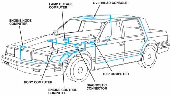
On the Chrysler application shown in Figure6-21, each module has its own microprocessor
Figure 6-21. The DaimlerChrysler EVIC system is an example of a vehicle data communications network that allows separate computers to share data and communicate with each other through serial data trans-
mission. (DaimlerChrysler Corporation)
connected to the data bus through the Chrysler Collision Detection (CCD) integrated circuit, which sends and receives data. The CCD circuit acts like a traffic control officer at a four-way intersection. If the data bus is not in use, it allows unrestricted transmission from a module. However, if one module is transmitting, it blocks the transmission of data from another module until the bus (intersection) is clear. If two or more modules start to transmit at the same time, or almost at the same time, the CCD circuit assigns a priority to the messages according to the identification code at the beginning of the transmission. If the CCD circuit blocks a message, the module that originally sent it retransmits the signal until it is successful.
Receivers work in one of two ways: they operate the electrical load directly, or they control a relay in the circuit to operate the load indirectly. They are not capable of making decisions on their own, but only carry out commands from the transmitter. However, they can send a feedback signal informing the transmitter that something is wrong with the system.
Optical Data Links
A variation of the serial data transmission approach to multiplexing substitutes optical data links or fiber-optic cables for the peripheral serial bus. The concept is the same, but light signals are substituted for voltage signals. An optical data link system operates with the transmitter and receivers described earlier, but a light-emitting diode (LED) in the transmitter sends light signals through the fiber-optic cables to a photo diode in the receiver. The light signals are decoded by the receiver, which then performs the required control function. Primarily Toyota and other foreign manufacturers have used this form of multiplexing. Because it uses light instead of voltage to transmit signals, system operation is not affected by EMI, nor does the system create interference that might have an adverse influence on other electrical systems in the vehicle.
Multiplex Advantages
Regardless of the type of multiplex system used, such a circuit offers several advantages over conventional wiring circuits used in the past, as follows: • The size and number of wires required for a given circuit can be greatly reduced. As a result, the complexity and size of wiring harnesses also are reduced. • The low-current-capacity switches used in a multiplex circuit allow the integration of


