4 minute read
Series-Parallel Circuits


of 2gallons per minute flows out of the tank. It will take 5 minutes to empty 10 gallons from thetank.
Notice that the faucets are connected like resistors in a parallel circuit. Because each faucet offers a path for water to flow, two paths offer less resistance than one. In the same way, two parallel paths offer less resistance than a single path and allow more total current to flow.
Current in a Parallel Circuit
The current is not the same throughout a parallel or series-parallel circuit. It is true that the same voltage is applied to each branch. But, because the resistance in each branch can be different, the current for each branch can also be different. To find the total current in a parallel or series-parallel circuit, add up the currents in all of the circuit branches. For example, you will find the current to be 21⁄2 amps in the circuit shown in Figure 5-12. The current of the main line is always the same as the total current because it is the only path for that part of thecircuit.
SERIES-PARALLEL CIRCUITS
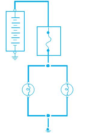
A series-parallel circuit is a circuit that contains both series circuits and parallel circuits. This type of circuit is also known as a combination circuit as shown in a circuit in Figure 5-13. The simple circuit in Figure 5-13has a 2-ohm resistor in series from the battery then splits into two parallel branches of first a 6-ohm resistor and then a 3-ohm resistor before recombining and returning to the battery. There is no specific law or formula that pertains to the whole seriesparallel circuit for voltage, amperage, and resistance. Instead, it is a matter of determining
Tail Light (2 Amps) Marker Light (1/2 Amp)
Figure 5-12. Current in a parallel circuit.(GM Service and
Parts Operations)
which branch loads of the circuit are in series and which are in parallel, simplifying the circuit where possible, and using the circuit laws that apply to each of these branches to find the value totals. For more information about series-parallel circuits, see the “Circuit Faults” section in Chapter 5of the Shop Manual.
Series-Parallel Circuits andOhm’s Law
Values in a series-parallel circuit are figured by reducing the parallel branches to equivalent values for single loads in series. Then the equivalent values and any actual series loads are combined. To calculate total resistance, first find the resistance of all loads wired in parallel. If the circuit is complex, it may be handy to group the parallel branches into pairs and treat each pair separately. Then add the values of all loads wired in series to the equivalent resistance of all the loads wired in parallel. In the circuit shown in Figure 5-13,
The equivalent resistance of the loads in parallel is
The total of the branch currents is 1 2 3 amps, so the voltage drop is E IR 3 2 6. The voltage drop across the load in series is 2 3 6 volts. Add these voltage drops to find the source voltage: 6 6 12 volts.
To determine the source voltage in a seriesparallel circuit, you must first find the equivalent
Rt R1 R2 R1 R2 6 3 6 3 2
18 9 + 2 = 4 ohms
Rt R1 R2 R1 R2 6 3 6 3 18 9 2 ohms
2 OHMS 3 AMPS
12 VOLTS 1 AMP 2 AMPS

6 OHMS 3 OHMS
Figure 5-13. Series-parallel circuit. resistance of the loads in parallel, and the total current through this equivalent resistance. Figureout the voltage drop across this equivalent resistance and add it to the voltage drops across all loads wired in series. To determine total current, find the currents in all parallel branches and add them together. This total is equal to the current at any point in the series circuit.
In Figure 5-13, notice that there is only 6 volts across each of the branch circuits because another 6 volts has already been dropped across the 2-ohm resistor.
Figure 5-14is a complete headlamp circuit with all bulbs and switches, which is an example of a series-parallel circuit.
I E
R1 E
R2 6 6 6 3 1 2 3 amps
Series-Parallel Circuit Exercise
Exercise Objective: Demonstrate that a seriesparallel circuit has the characteristics of both a series circuit and a parallel circuit. Assemble the circuit shown in Figure 5-15and answer the following questions.
Figure 5-14. A complete headlamp circuit with allbulbs and switches, which is a series-parallel circuit.
RESISTORS R1 100 ohms / 0.5 W R2 10,000 ohms / 0.5 W R3 1,000 ohms / 0.5 W R4 100 ohms / 0.5 W
FUSE (7.5A)
R1 R2 R3 R4 100 ohms 100 ohms 1,000 ohms 10,000 ohms
Location #1

Location #2 Location #3
Figure 5-15. Series-parallel circuit exercise.(GM Service and Parts Operations)
1. Measure the voltage drop at location #1 and #2.
________________________________________ 2. Measure the resistance at location #1.
________________________________________ 3. Measure the resistance of each resistor in the parallel portion of the circuit.
________________________________________ 4. Use Ohm’s Law to figure out the total resistance for the parallel circuit.
________________________________________ 5. Measure the resistance at location #2. Does it match your calculation?
________________________________________ 6. Measure the resistance at location #3. 7. Does the resistance at location #1 and #2 addup to the resistance you measured at location #3?
________________________________________ 8. Calculate the total circuit current using
Ohm’s Law.
________________________________________ 9. Measure the total circuit current. Does it match your calculation?
________________________________________ 10. Measure the current of each branch of the parallel portion of the circuit.


