
9 minute read
Electromagnetism


Magnetic Fields and Lines ofForce
A magnetic field (Figure 4-3) is made up of many invisible lines of force, which are also called lines of flux. Magnetic flux is another term applied to lines of force, which can be compared to current in electricity: They come out of one pole and enter the other pole. The flux lines are concentrated at the poles and spread out into the areas between the poles.
Magnetic Field Intensity
The magnetic field intensity refers to the magnetic field strength (force) exerted by the magnet and can be compared to voltage in electricity. The magnetic field existing in the space around a magnet can be demonstrated if a piece of cardboard is placed over a magnet and iron filings are sprinkled on top of the cardboard. The iron filings will be arranged in a pattern showing the flux lines.A weak magnet has relatively few flux lines; a strong magnet has many. The number of flux lines is sometimes described as flux density, as shown in Figure 4-4.
Figure 4-3. Magnetic field/lines of force.
Magnetism Summary
• Magnetic flux lines leave the north pole and enter the south pole of the magnet. • The more powerful the magnet, the higher the flux density or concentration of the lines of force. • The greatest flux density occurs at the poles. • Magnetic lines of force are always parallel and never cross. • Like poles repel and unlike poles attract.
Atomic Theory and Magnetism
Magnetism starts with the atom. Each atom has electrons spinning around the nucleus in orbits, as well as spinning on their own axis. It is this spinning of the electrons that creates small permanent magnets. In most elements, the electrons spin in opposite directions and as a result do not form a magnetic field. The iron atom has 26 electrons and 22 of these cancel themselves out because they have an opposite spin direction. However, the four in the next to last outer shell all spin in the same direction, giving iron a magnetic characteristic.
ELECTROMAGNETISM
In 1820, scientists discovered that current-carrying conductors are surrounded by a magnetic field. A conductor, such as a copper wire, that is carrying an electrical current creates a magnetic field around the conductor and is called electromagnetism.

Figure 4-4. Flux density equals the number of lines of force per unit area.
CONDUCTOR MOVEMENT CONDUCTOR MOVEMENT
Compass deflects From North to South Compass deflects From North to South

Figure 4-5. Electromagnet.
This magnetic field can be observed by the use of a compass, as shown in Figure 4-5. The polarity of the magnetic field changes depending on the direction in which the magnetic field is created.
Straight Conductor
The magnetic field surrounding a straight, currentcarrying conductor consists of several concentric cylinders of flux the length of the wire, as in Figure4-6. The strength of the current determines how many flux lines (cylinders) there will be and how far out they extend from the surface of the wire.
Electromagnetic Field Rules
The following rules apply with electromagnetic fields: • The magnetic field moves only when the current through the conductor is changing— either increasing or decreasing. • The strength of the magnetic field is directly proportional to the current flow through the conductor. The greater the current flow, the stronger the magnetic field. If the current flow is reduced, the magnetic field becomes weaker.
Left-Hand Rule
Magnetic flux cylinders have direction, just as the flux lines surrounding a bar magnet have direction. The left-hand rule is a simple way to determine this direction. When you grasp a conductor with your left hand so that your thumb points in the direction of electron flow ( to+) through the conductor, your fingers curl around the wire in the direction of the magnetic flux lines, as shown in Figure 4-7.
Right-Hand Rule
It is important to note at this point that in automotive electricity and magnetism, we use the conventional theory of current (+ to ), so you use the right-hand rule to determine the direction of the magnetic flux lines, as shown in Figure 4-8. The right-hand rule is used to denote the direction of the magnetic lines of force, as follows: The right hand should enclose the wire,
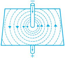
Figure 4-6. A magnetic field surrounds a straight current-carrying conductor.
Figure 4-7. Left-hand rule for field direction; used with the electron-flow theory.

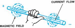
Figure 4-8. Right-hand rule for field direction; used with the conventional flow theory.
with the thumb pointing in the direction of conventional current flow (positive to negative), and the finger tips will then point in the direction of the magnetic lines of force, as shown in Figure48. For the rest of this chapter,the electron-flow theory (negative to positive) and the left-hand rule are used.
Field Interaction
The cylinders of flux surrounding current-carrying conductors interact with other magnetic fields. In the following illustrations, the cross symbol (+) indicates current moving inward, or away from you. It represents the tail of an arrow. The dot symbol (.) represents an arrowhead and indicates current moving outward, or toward you (Figure 4-9).
If two conductors carry current in opposite directions, their magnetic fields are also in opposite directions (according to the left-hand rule). If they are placed side by side, Figure 4-10, the opposing flux lines between the conductors create a strong magnetic field. Current-carrying conductors tend to move out of a strong field into a weak field, so the conductors move away from each other (Figure 4-11).
If the two conductors carry current in the same direction, their fields are in the same direction. As seen in Figure 4-12, the flux lines between the two conductors cancel each other out, leaving a very weak field. In Figure 4-13, the conductors are drawn into this weak field; that is, they move closer together.
Motor Principle
Electric motors, such as automobile starter motors, use field interaction to change electrical energy into mechanical energy (Figure 4-14). If
Figure 4-9. Current direction symbols.

Figure 4-10. Conductors with opposing magnetic fields.

Figure 4-11. Conductors will move apart into weaker fields.

Figure 4-12. Conductors with the same magnetic fields.
two conductors carrying current in opposite directions are placed between strong north and south poles, the magnetic field of the conductor
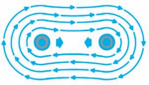
Figure 4-13. Conductors will move together into the weak field.
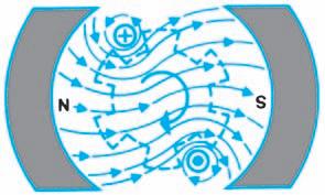
Figure 4-14. Electric motors use field interaction to produce mechanical energy and movement.
interacts with the magnetic fields of the poles. The clockwise field of the top conductor adds to the fields of the poles and creates a strong field beneath the conductor. The conductor tries to move up to get out of this strong field. The counterclockwise field of the lower conductor adds to the field of the poles and creates a strong field above the conductor. The conductor tries to move down to get out of this strong field. These forces cause the center of the motor or armature where the conductors are mounted to turn in a clockwise direction. This process is known as magnetic repulsion. For more information about electric motors, see the section on “Diagnostic Strategies” in Chapter 4 of the Shop Manual.
Loop Conductor
Bending the wire into a loop can strengthen the field around a straight conductor. As the wire is bent, the fields, which meet in the center of the
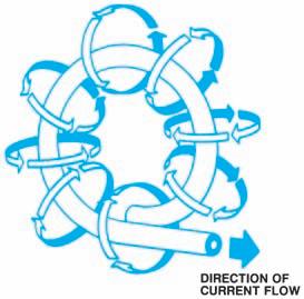
Figure 4-15. Loop conductor. (Delphi Corporation)

Figure 4-16. Coil conductor.
loop, combine their strengths (Figure 4-15). The left-hand rule also applies to loop conductors.
Coil Conductor
If several loops of wire are made into a coil, the magnetic flux density is further strengthened. Flux lines around a coil are the same as the flux lines around a bar magnet (Figure 4-16). They exit from the north pole and enter at the south pole. Use the left-hand rule to determine the north pole of a coil. If you grasp a coil with your left hand so that your fingers point in the direction of electron flow, your thumb points toward the north pole of the coil, Figure 4-17. Increasing the number of turns in the wire, or increasing the current through the coil, or both, can strengthen the magnetic field of a coil.

Figure 4-17. Left-hand rule for a coil.
Electromagnets
There is a third way to strengthen the magnetic field surrounding a current-carrying conductor. Because soft iron is very permeable, magnetic flux lines pass through it easily. If a piece of soft iron is placed inside a coiled conductor, the flux lines concentrate in the iron core, as shown in Figure 4-18, rather than pass through the air, which is less permeable. This concentration of force greatly increases the strength of the magnetic field inside the coil. Acoils with an iron core is called an electromagnet.
Electromagnetic field force is often described as magnetomotive force (mmf). The strength of the magnetomotive force is determined by: • The higher the current flow through the coil, the stronger the mmf. • The higher the number of turns of wire in the coil, the higher the mmf.
Magnetomotive force is measured in units of ampere-turns, abbreviated AT. For example, a coil with 100 turns carrying one ampere would generate a magnetomotive force of 100 AT. The same 100 ATcan be generated by a coil with only 10 turns of wire if 10 amperes were flowing. The actual magnetic field depends on the design of the coil and if it does nor does not use a soft iron core.
Relays
One common automotive use of electromagnets is in a device called a relay. A relay is a control device that allows a small amount of current to trigger a large amount of current in another circuit. Asimple relay (Figure 4-19) contains an electromagnetic coil in series with a battery and a switch. Near the electromagnet is a movable flat blade, or armature, of some material that is attracted by a magnetic field. The armature pivots at one end and is held a small distance away from the electromagnet by a spring (or by the spring steel of the armature itself). Acontact point made of a good conductor is attached to the free end of the armature. Another contact point is fixed a small distance away. The two contact points are wired in series with an electrical load and the battery. When the switch is closed, the following occurs:
1. Current travels from the battery through the electromagnet. 2. The magnetic field created by the current attracts the armature, bending it down until the contact points meet. 3. Closing the contacts allows current in the second circuit from the battery to the load.
When the switch is opened, the following occurs:
1. The electromagnet loses its current and its magnetic field. 2. Spring pressure brings the armature back. 3. The opening of the contact points breaks the second circuit.
Relays may also be designed with normally closed contacts that open when current passes through the electromagnet.

Figure 4-18. Electromagnets.


