11 minute read
Electromagnetic Induction


86 30
85 87 87A
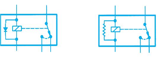
Figure 4-19. Electromagnetic relay.
Most relays contain a device that protects circuitry from the voltage spike that occurs when the coil is de-energized. In older vehicles, the protective device is usually a diode (as in the circuit on the left in Figure 4-19). Adiode is a semiconductor device that can be useful in several ways. In a relay, the diode is located in parallel with the coil, where it dissipates the voltage spike. (You’ll learn more about how diodes work in a Chapter 10.)
Today many automobile relays include a resistor, rather than a diode, to protect the control circuit (as in the circuit on the right in Figure 4-19). The resistor dissipates the voltage spike in the same way that a diode does. For more information about relays, see the section on “Diagnostic Strategies” in Chapter 4of the Shop Manual.
ISO Relays
In Figure 4-19,on the right, the five terminals with specific numbers assigned to them (#85, #86, etc.) show that this relay, like many others now used in vehicles, is an ISO relay. ISO relays, as required by the International Organization for standardization (ISO), are the same size and have the same terminal pattern. They’re used in many majorcomponent circuits, and are often located in a vehicle’s underhood junction block or power distribution center. For more information about ISO relays, see the section on “Diagnostic Strategies” in Chapter 4of the Shop Manual.
ELECTROMAGNETIC INDUCTION
Only a decade after the discovery of magnetic fields surrounding current-carrying conductors, more discoveries were made about the relationship between electricity and magnetism. The modem automotive electrical system is based in great part upon the principles of electromagnetic induction discovered in the 1830s. Along with creating a magnetic field with current, it is also possible to create current with a magnetic field. Magnetic flux lines create an electromotive force, or voltage, in a conductor if either the flux lines or the conductor is moving (relative motion). This process is called electromagnetic induction, and the resulting electromotive force is called induced voltage (Figure 4-20). If the conductor is in a complete circuit, current exists.
It happens when the flux lines of a magnetic field cut across a wire (or any conductor). It does not matter whether the magnetic field moves or the wire moves. When there is relative motion between the wire and the magnetic field, a voltage is produced in the conductor. The induced voltage causes a current to flow; when the motion stops, the current stops.
Voltage is induced when magnetic flux lines are broken by a conductor (Figure 4-20). This relativemotion can be a conductor moving across
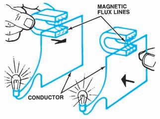
Figure 4-20. Voltage can be induced by the relative motion between a conductor and a magnetic field.
a magnetic field (as in a DC generator), or a magnetic field moving across a stationary conductor (as in AC generators and ignition coils). Inboth cases, the induced voltage is caused by relative motion between the conductor and the magnetic flux lines.
Voltage Strength
Induced voltage depends upon magnetic flux lines being broken by a conductor. The strength of the voltage depends upon the rate at which the flux lines are broken. The more flux lines broken per unit of time, the greater the induced voltage. If a single conductor breaks one million flux lines per second, 1 volt is induced.
There are four ways to increase induced voltage, as follows:
• Increase the strength of the magnetic field, so there are more flux lines. • Increase the number of conductors that are breaking the flux lines. • Increase the speed of the relative motion between the conductor and the flux lines so that more lines are broken per time unit. • Increase the angle between the flux lines and the conductor to a maximum of 90 degrees.
No voltage is induced if the conductors move parallel to, and do not break any, flux lines, as shown in Figure 4-21. Maximum voltage is induced if the conductors break flux lines at 90 degrees (Figure 4-22). Induced voltage varies proportionately at angles between 0 and 90 degrees.
We know voltage can be electromagnetically induced, and we can measure it and predict its behavior. Induced voltage creates current. The direction of induced voltage (and the direction in which current moves) is called polarity and depends upon the direction of the flux lines and the direction of relative motion. An induced current moves so that its magnetic field opposes themotion that induced the current. This principle, called Lenz’s Law, is based upon Newton’s observation that every action has an equal and opposite reaction. The relative motion of a conductor and a magnetic field is opposed by the magnetic field of the current it has induced. This is why induced current can move in either direction, and it is an important factor in the design and operation of voltage sources such asalternators.
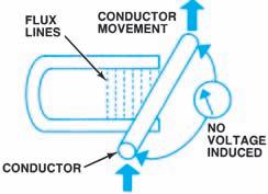
Figure 4-21. No voltage is induced if no flux lines are broken.
DC Generator Principles
The principles of electromagnetic induction are employed in generators for producing DC current. The basic components of a DC generator are shown in Figure 4-23. Aframework composed of laminated iron sheets or an other ferromagnetic metal has a coil wound on it to form an electromagnet. When current flows through this coil, magnetic fields are created between the pole pieces, as shown. Permanent magnets could also be employed instead of the electromagnet.
To simplify the initial explanation, a single wire loop is shown between the north and south pole pieces. When this wire loop is turned within the magnetic fields, it cuts the lines of force and avoltage is induced. If there is a complete circuit from the wire loop, current will flow. The wire loop is connected to a split ring known as a commutator, and carbon brushes pick off the electric energy asthe commutator rotates. Connecting wires from the carbon brushes transfer the energy to the load circuit.
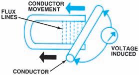
Figure 4-22. Maximum voltage is induced when the flux lines are broken at a 90-degree angle.
Figure 4-23. Direct current (DC) voltage generated in a rotating loop conductor.
When the wire loop makes a half-turn, the energy generated rises to a maximum level, then drops to zero, as shown in parts B and C of Figure4-23. As the wire loop completes a full rotation the induced voltage would reverse itself and the current would flow in the opposite direction (AC current) after the initial half-turn. To provide for an output having a single polarity (DC current), a split-ring commutator is used. Thus, for the second half-turn, the carbon brushes engage commutator segments opposite to those over which they slid for the first half-turn, keeping the current in the same direction. The output waveform is not a steady-level DC, but rises and falls to form a pattern referred to as pulsating DC. Thus, for a complete 360-degree turn of the wire loop, two waveforms are produced, as shown in Figure 4-23.
The motion of a conductor may induce DC voltage across a stationary magnetic field. This is the principle used to change mechanical energy to electrical energy in a generator. Alooped conductor is mechanically moved within the magnetic field created by stationary magnets, as in Figure 4-23. InFigure 4-23A, the voltage is zero because the conductor motion is parallel to the flux lines. As the conductor moves from Ato B, the voltage increases because it is cutting across the flux lines. At B, the voltage is at a maximum because the conductor is moving at right angles to the flux lines, breaking the maximum number.
From position B to C, the voltage decreases to zero again because fewer lines are broken. At C, the conductor is again parallel to the flux lines. As the conductor rotates from C to D, voltage increases. However, the induced voltage is in the opposite direction because the conductor is cutting the flux lines in the opposite direction. From position D to E, the cycle begins to repeat. Figure 4-23shows how voltage is induced in a loop conductor through one complete revolution in a magnetic field. The induced voltage is called alternating current (AC) voltage because it reverses direction every half cycle, as shown on the graph at the bottom of thefigure. Because automotive battery voltage is always in one direction, the current it produces always flows in one direction. This is called direct current (DC). Alternating current cannot be used tocharge the battery, so the AC must be changed (rectified) to DC. This is done in a generator by thecommutator. In a simple, single-loop generator, the commutator would be a split ring of conductive material connected to the ends of the conductor. Brushes of conductive material ride on the surface of the two commutator segments.
Induced current travels from the conductor through the commutator and out through the brushes (Figure 4-24A). At the instant the looped conductor is turned so that the induced current changes direction (Figure 4-24B), the commutator also rotates under the brushes, so that the brushes now contact the opposite commutator segments. Current now flows out of the other half of the commutator, but the same brush is there to receive it. This design is called a brush-rectified, or commutator-rectified, generator, and the output is called pulsating direct current. Actual DC generators have many armature windings and commutator segments. The DC voltages overlap to create an almost continuous DC output.
Figure 4-24. The commutator and brushes conduct pulsating direct current from the looped conductor.
AC Generator (Alternator) Principles
Since 1960, virtually all automobiles have usedan AC generator (alternator), in which the movement of magnetic lines through a stationary conductor (Figure 4-25) generates voltage. Amagnet called a rotor is turned inside astationary looped conductor called a stator (Figure 4-25). The induced current, like that of a DC generator, is constantly changing its direction. The rotation of the magnetic field causes the stator to be cut by flux lines, first in one direction and then the other. The AC must be rectified to match the battery DC by using diodes, which conduct current in only one direction. This design is called a diode-rectified alternator. We will study diodes in Chapter 10and alternators in Chapter 8of thisbook.
See the section on “Diagnostic Strategies” in Chapter 4 of the Shop Manual.
Self-Induction
Up to this point, our examples have depended upon mechanical energy to physically move either the conductor or the magnetic field. Another form of relative motion occurs when a magnetic field is forming or collapsing. When current begins to flow in a coil, the flux lines expand as the magnetic
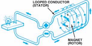
Figure 4-25. A simplified alternator.
field forms and strengthens. As current increases, the flux lines continue to expand, cutting through the wires of the coil and actually inducing another voltage within the same coil, which is known as self-induction. Following Lenz’s Law, this selfinduced voltage tends to oppose the current that produces it.If the current continues to increase, the second voltage opposes the increase. When the current stabilizes, the counter voltage is no longer induced, because there are no more expanding flux lines (norelative motion). When current to the coil is shut off, the collapsing magnetic flux lines self-induce a voltage in thecoil that tries to maintain the original current. The self-induced voltage opposes and slows down the decrease in the original current. The self-induced voltage that opposes the source voltage is called counterelectromotive force (CEMF).
Mutual Induction
When two coils are close together, energy may be transferred from one to the other by magnetic coupling called mutual induction. Mutual induction means that the expansion or collapse of the magnetic field around one coil induces a voltage in thesecond coil. Usually, the two coils are wound on the same iron core. One coil winding is connected to a battery through a switch and is called the primary winding. The other coil winding is connected to an external circuit and is called the secondary winding.
When the switch is open (Figure 4-26A), there is no current in the primary winding. There is no magnetic field and, therefore, no voltage in the secondary winding. When the switch is closed (Figure 4-26B), current is introduced and a magnetic field builds up around both windings. The primary winding thus changes electrical energy from the battery into magnetic energy of the expanding field. As the field expands, it cuts across the secondary winding and induces a voltage in it. Ameter connected to the secondary circuit shows current.
When the magnetic field has expanded to its full strength (Figure 4-26C), it remains steady as long as the same amount of current exists. Theflux lines have stopped their cutting action. There is no relative motion and no voltage in the secondary winding, as shown on the meter. When the switch is opened (Figure 4-26D), primary current stops and the field collapses. As it does, flux lines cut across the secondary winding, but in the opposite direction. This induces a secondary voltage with current in the opposite direction, as shown on the meter.
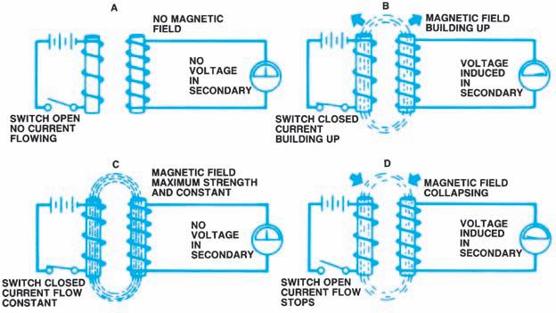
Figure 4-26. Mutual induction.


