8 minute read
Machine Disassembly and Replacement


This chapter contains step-by-step procedures on how to disassemble the notebook computer Aspire 6935 for maintenance and troubleshooting. To disassemble the computer, you need the following tools: Wrist grounding strap and conductive mat for preventing electrostatic discharge Small Philips screw driver hilips screwdriver Plastic flat head screw driver Tweezers
NOTE: The screws for the different components vary in size. During the disassembly process, group the screws with the corresponding components to avoid mismatch when putting back the components. When you remove the stripe cover, please be careful not to scrape the cover.
Before You Begin
Before proceeding with the disassembly procedure, make sure that you do the following: 1. Turn off the power to the system and all peripherals. 2. Unplug the AC adapter and all power and signal cables from the system. 3. Remove the battery pack.
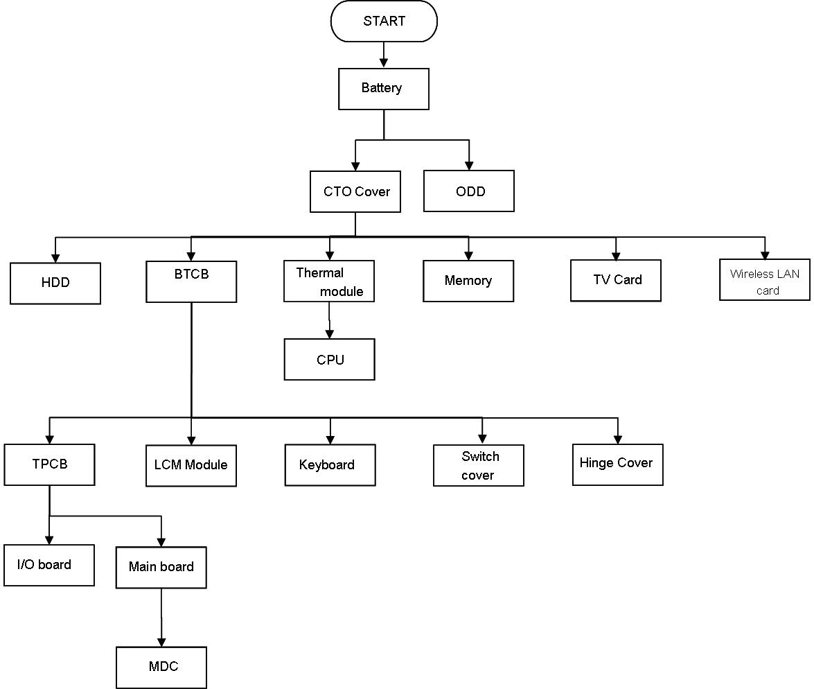
The flowchart on the succeeding page gives you a graphic representation on the entire disassembly sequence and instructs you on the components that need to be removed during servicing. For example, if you want to remove the system board, you must first remove the keyboard, then disassemble the inside assembly frame in that order.
Main unit disassembly flow chart
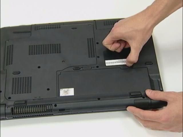
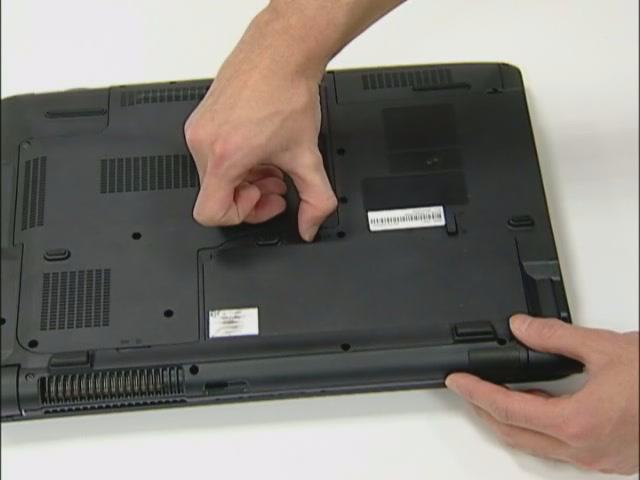
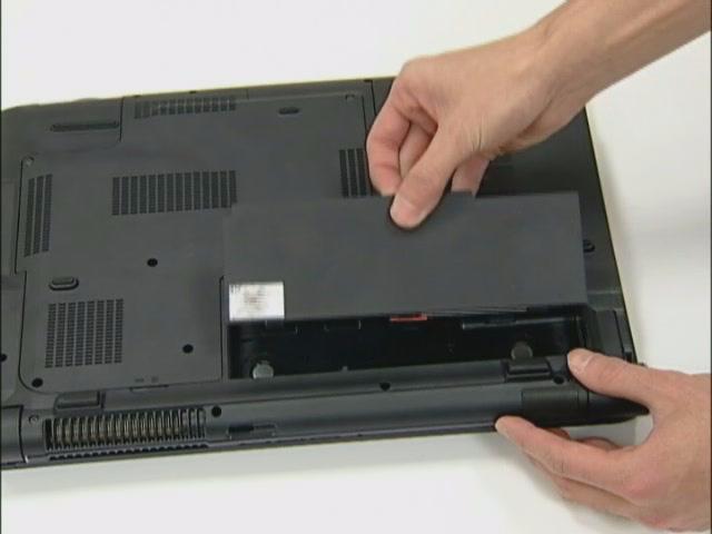
1. Release the battery. 2. Slide the battery latch then remove the battery.
Removing HDD/Wirless Cover/RAM Module/Wireless LAN Card/ TV Tunder Card/System Fan/ Thermal Module/CPU/ODD/Dummy cards
Removing the HDD
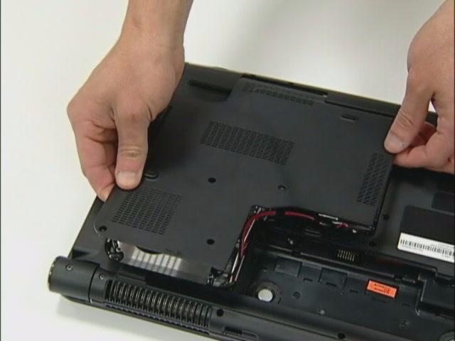
1. Remove the six screws fastening the CTO cover. 2. Detach the CTO cover from the notebook.

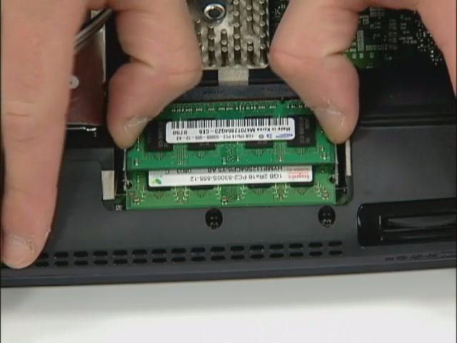
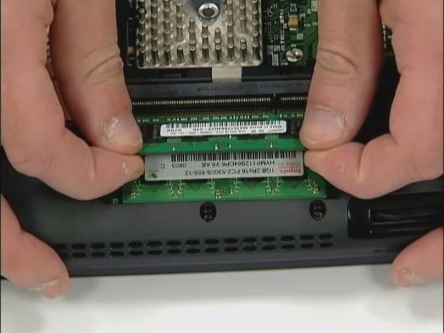
Removing the Wireless Cover & RAM Module
3. Remove one screw to release the Wireless cover. 4. Remove the Wireless cover from the notebook. 5. Pop out the memory module from the DIMM socket then remove it (If the notebook has two memory modules, then repeat this step).
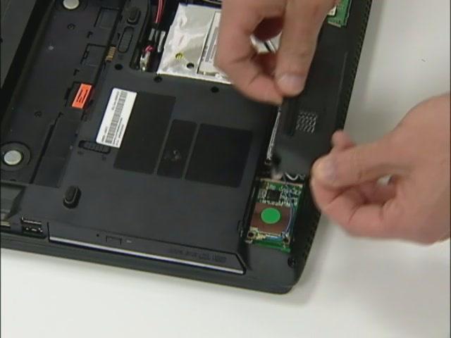
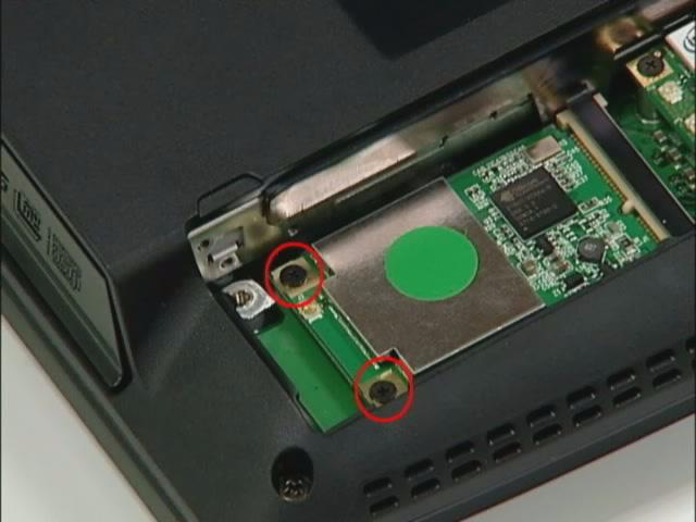
Removing the Wireless LAN Card/TV Tunder Card and System Fan
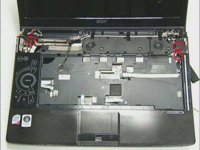
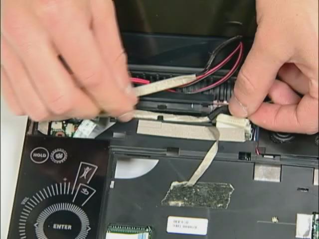
6. Pull out the Wireless antenna. 7. Remove the two screws fastening the wireless LAN card.
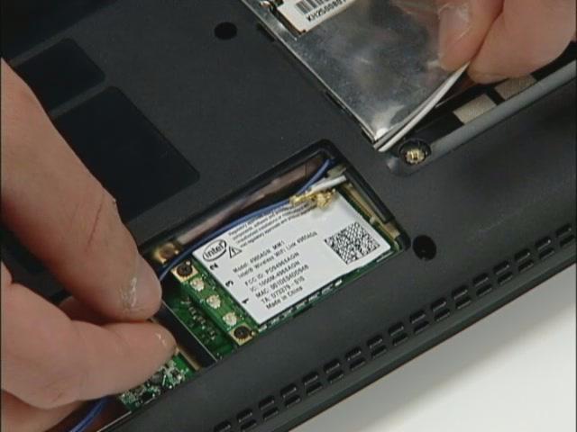
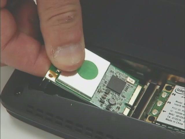
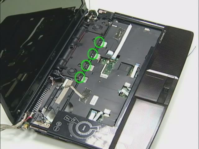
8. Disconnect the main and auxiliary antennae from the wireless LAN card. 9. Then take out the wireless LAN card from the main unit. 10. Loose two screws from the TV card. 11. Remove the TV card from the machine.
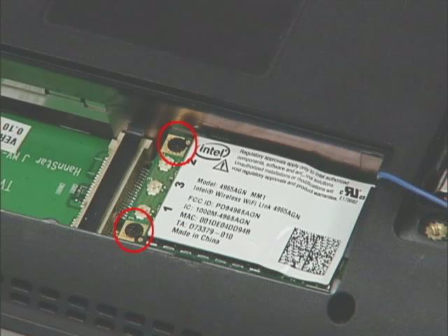
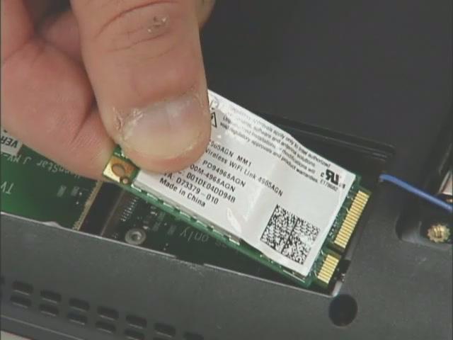
12. Remove the two screws from the Wireless card. 13. Remove the Wireless card from the machine.
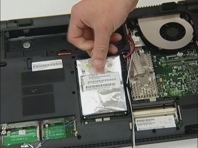
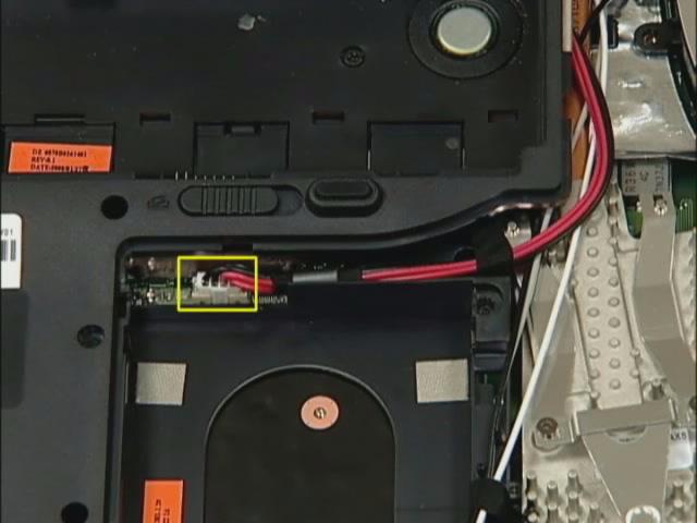
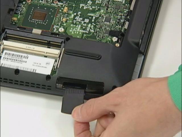
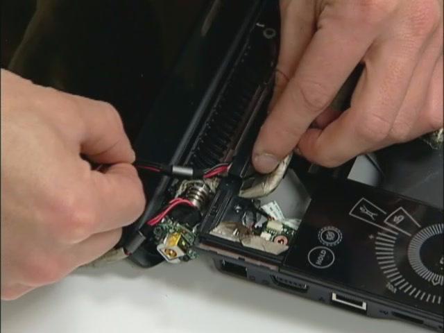
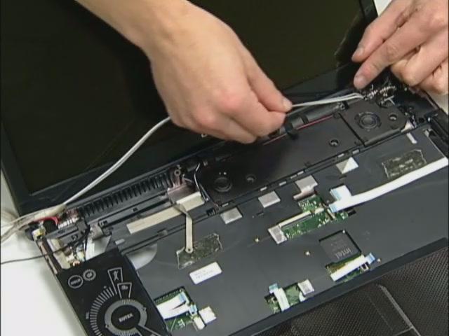
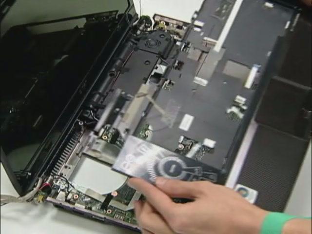
14. Remove HDD module as shown. 15. Unplug power cable from the machine.
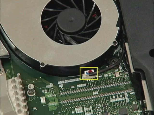
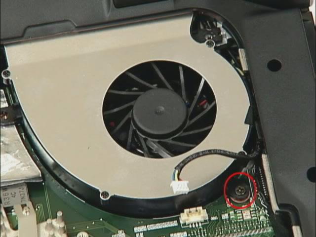
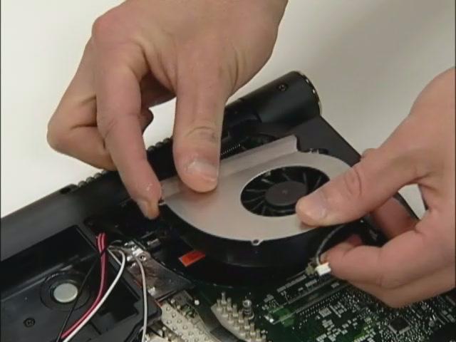
16. Remove FAN cable from the machine. 17. Loose the FAN screw. 18. Take out the system fan from the main unit as shown.
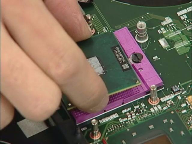
Removing the Thermal Modules and the CPU
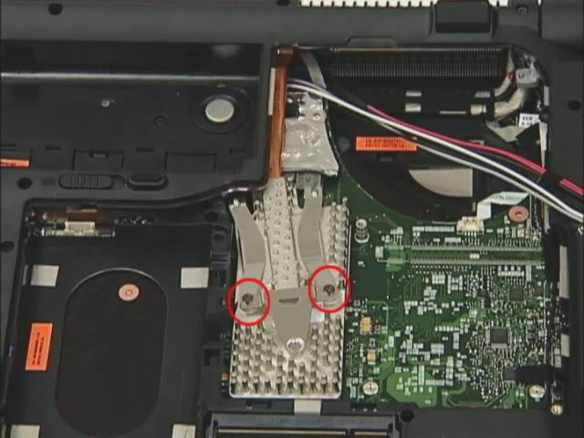
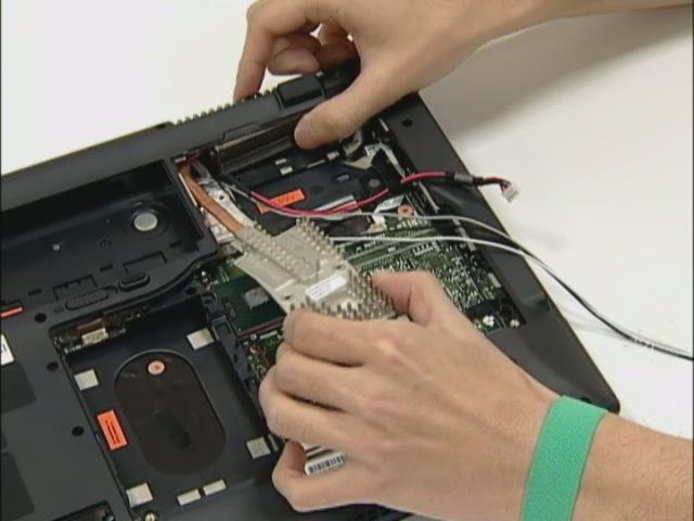
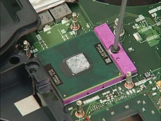
19. Remove the two screws holding the finger heatsink. 20. Detach the finger heatsink from the main board. 21. Then take out the CPU heatsink from the main board. 22. Use a flat screwdriver to release the CPU lock (Turn counter clock-wise) then remove the CPU carefully.
23. Remove the Express dummy card. 24. Remove the card reader dummy.
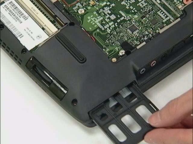
Removing the ODD and Dummy cards
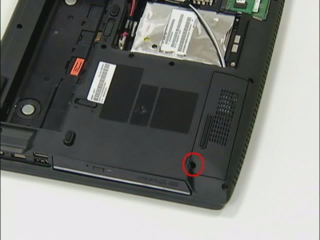
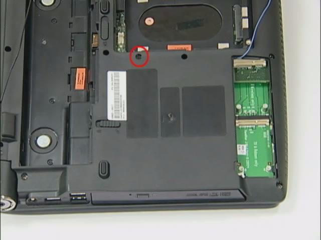
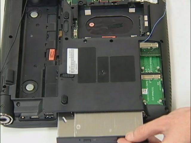
25. Remove the screw fastening the optical disk drive module on the bottom. 26. Use a tool to push the optical disk drive module outwards and remove the ODD module.
Removing the Hinge cover
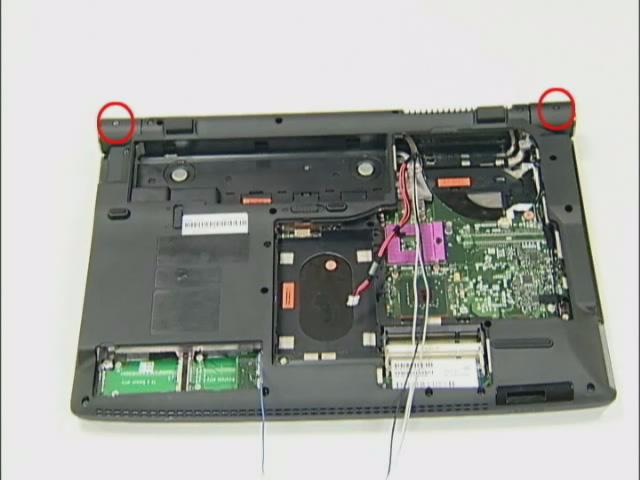
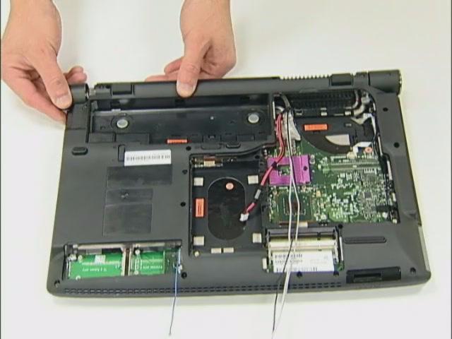
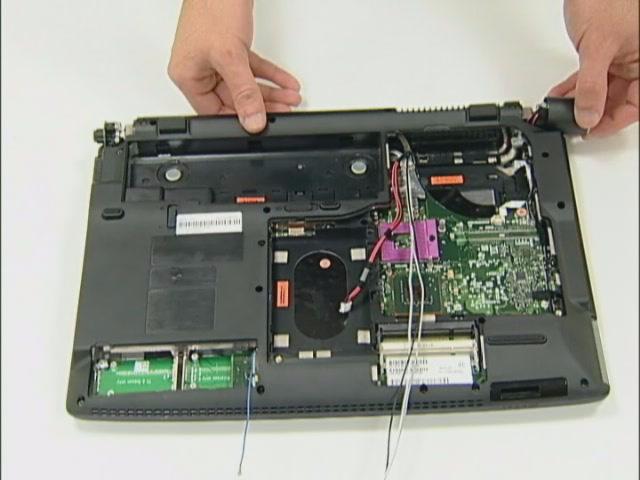
27. Remove two hinge cover screws. 28. Then detach the Hinge cover from both side.
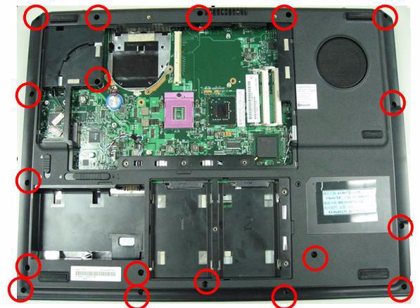
29. Loose 21 screws from BTCB.
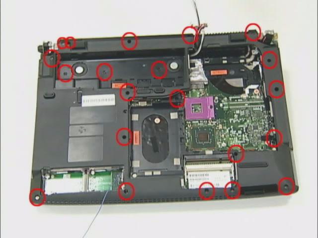
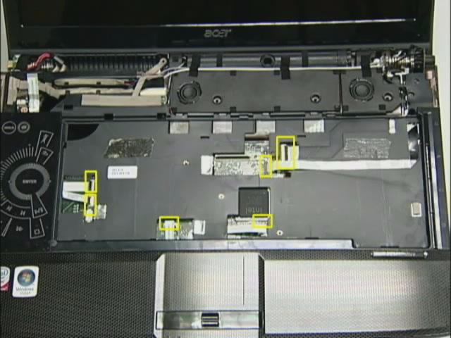
30. Detach Switch cover.

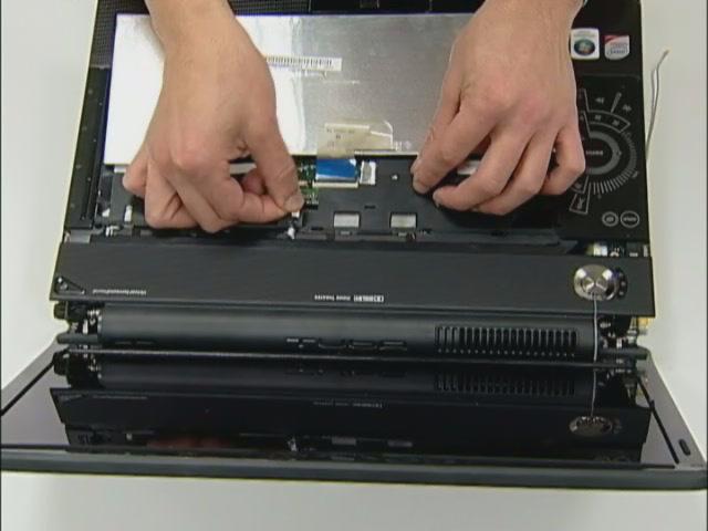
31. Disconnect Media board FFC from the Switch cover.
1. Turn over the keyboard as the image shows. 2. Disconnect the Keyboard FFC from the main board. 3. Then remove the keyboard from the main unit.
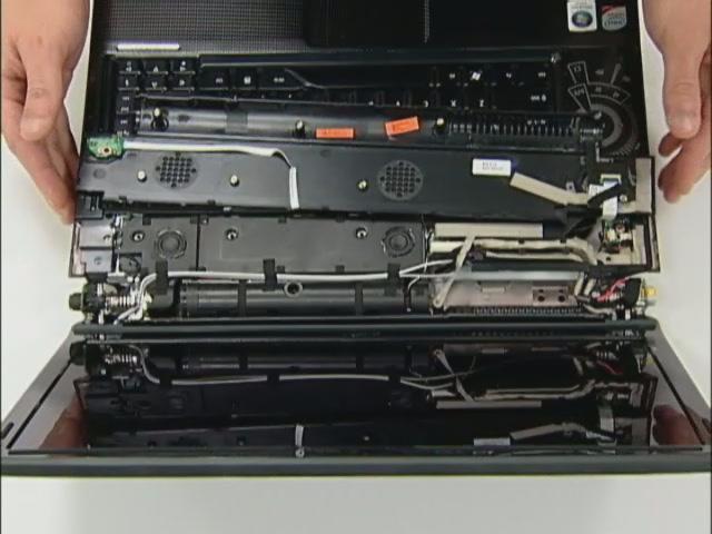
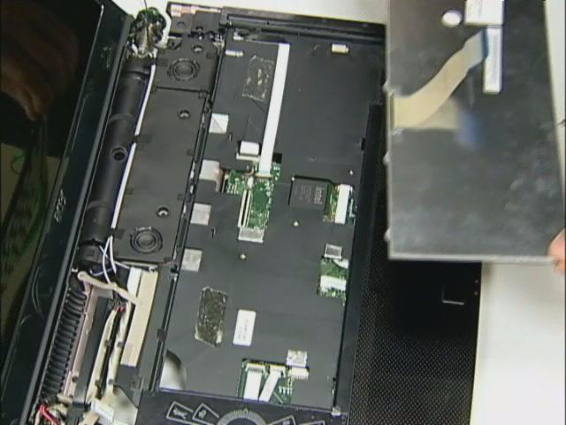
4. Remove the 18 screws fastening the upper case and the lower case assembly as shown. 5. Disconnect the FFC from the main board.
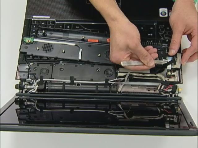
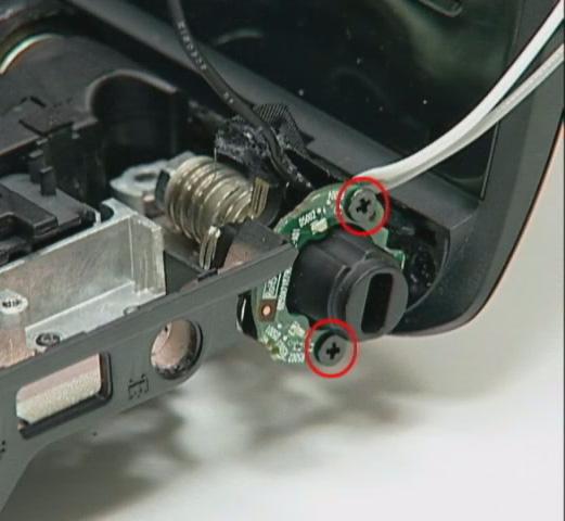
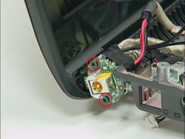
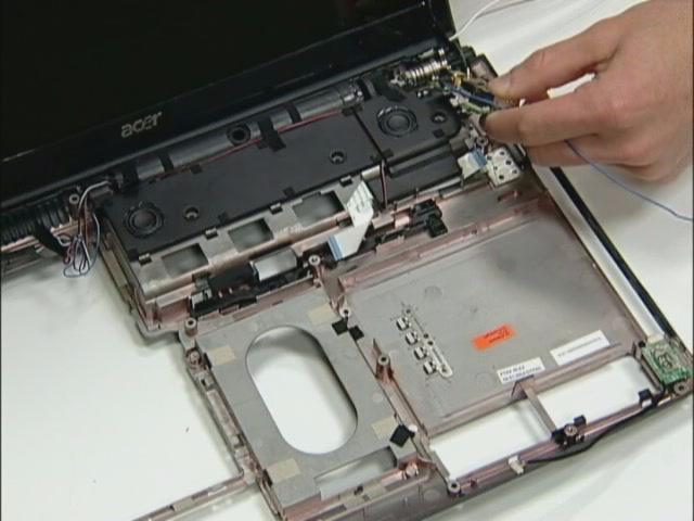
6. Loose two screws from the TPCB. 7. Disconnect the LCM cable. 8. Pull out the Power cable. 9. Pull out the Wireless antenna. 10. Release four TPCB locker then remove the TCB from machine.
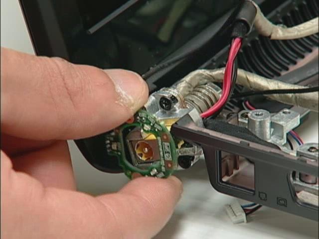
Disassembling the LED boards
11. Loose the LED boards four screws. 12. Remove two LED boards from the machine.
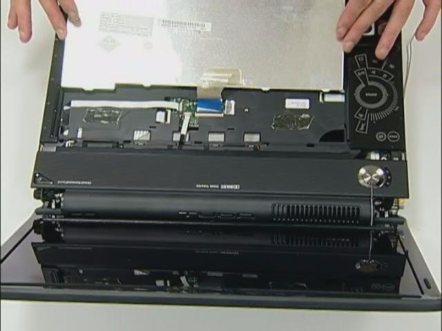
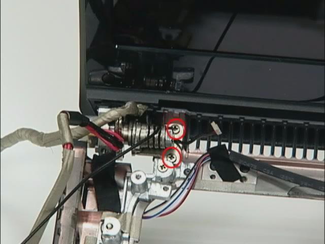
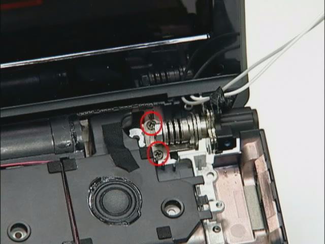
13. Loose four LCM hinge screws. 14. Then remove LCM module from the machine.
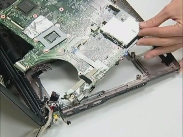
Remove I/O baord and Main Board
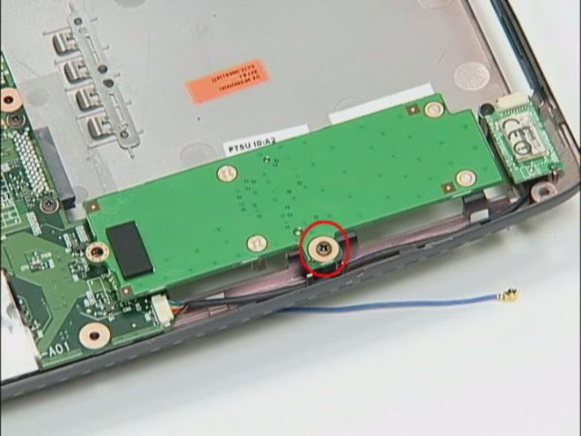
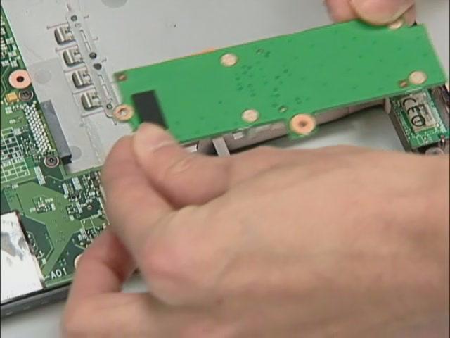
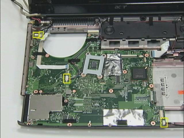
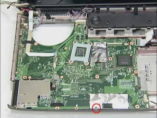
15. Loose the daughter board screw then remove the daughter board from the machine. 16. Disconnect four cables on the M/B as shown. 17. Loose the M/B screw, remove RJ11 connector from the BTCB. 18. Remove M/B from the BTCB.
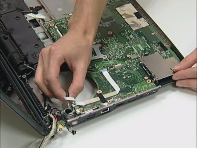
19. Disconnect LED/B cable and USB/B FFC. 20. Remove the USB board from BTCB.
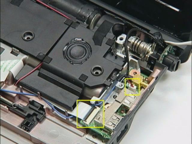
21. Loose two Modem card screws. 22. Disconnect Modem card cable. 23. Remove Modem card from the M/B.
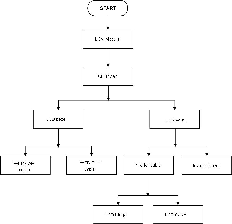
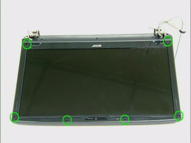
Disassembly LCM module
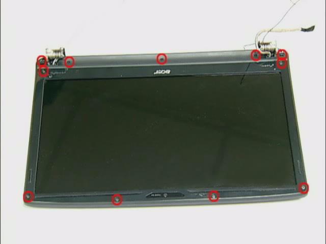
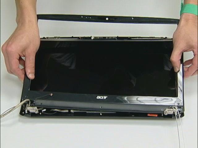
1. Remove six LCM bezel mylar. 2. Loose 11 LCM bezel screws. 3. Remove LCM bezel.
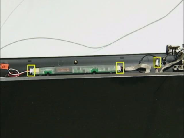
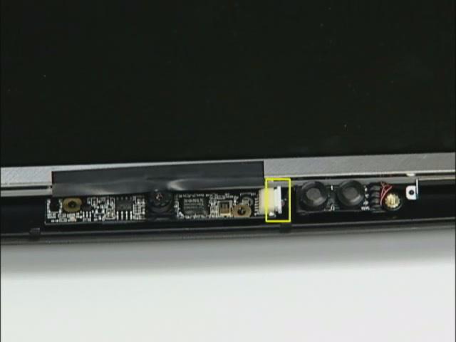
4. Disconnect Inverter cable and Back LED board cable. 5. Disconnect CCD cable.
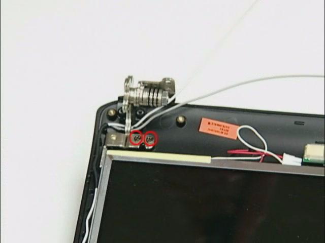
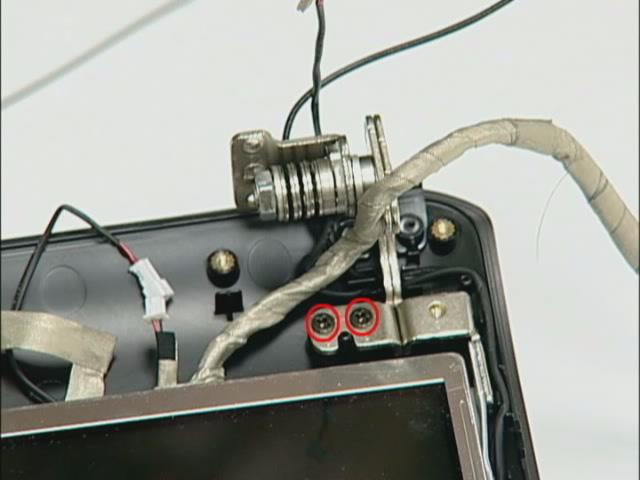
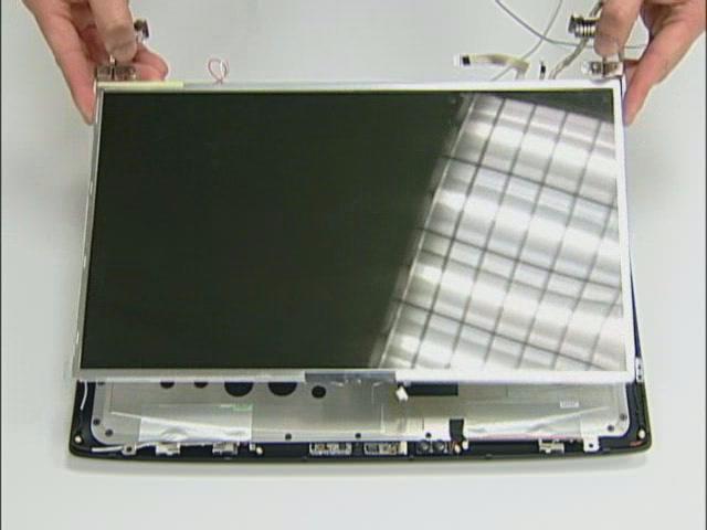
6. Loose four LCD scrws from the hinge. 7. Remove the LCD panel.
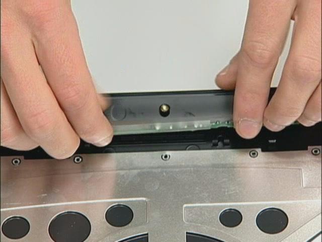
8. Remove the Inverter board.
9. Loose four LCD hinge screws, then remove two hinges from LCD panel.
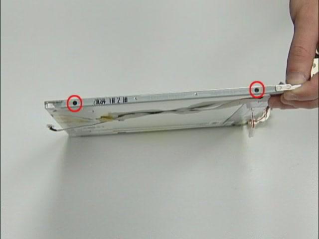
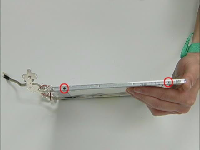
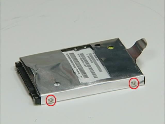
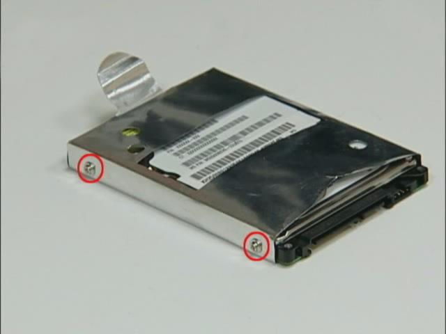
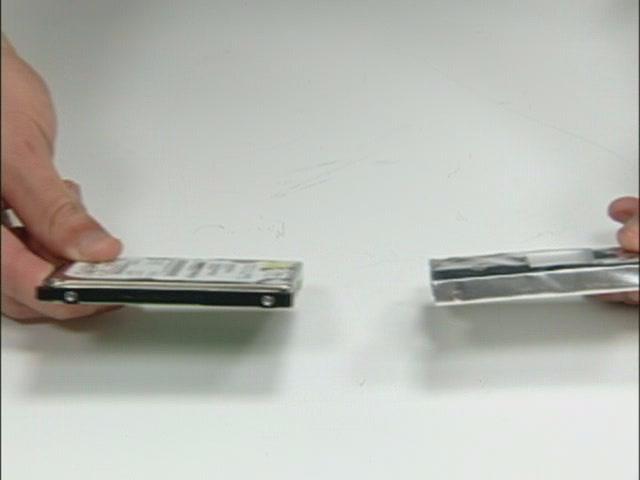
Disassembling the HDD Module
1. Remove the four screws holding the HDD (hard disk drive) foil; two on each side. 2. Carefully take out the hard disk drive from the HDD foil.
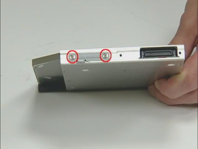
Disassembling the ODD Module
1. Remove the two screws holding the optical bracket. 2. Then remove the optical bracket from the optical disk drive.