12 minute read
Chapter 2 System Utilities


System Utilities
BIOS Setup Utility
The BIOS Setup Utility is a hardware configuration program built into your computer’s BIOS (Basic Input/ Output System). Your computer is already properly configured and optimized, and you do not need to run this utility. However, if you encounter configuration problems, you may need to run Setup. Please also refer to Chapter 4 Troubleshooting when problem arises. To activate the BIOS Utility, press m during POST (when “Press <F2> to enter Setup” message is prompted on the bottom of screen). Press m to enter setup; press <C> to boot from CD-ROM; press <F12> to change boot device.
There are six menu options: Info., Main, System Devices, Security, Boot, and Exit. Follow these instructions: To choose a menu, use the cursor left/right keys (zx). To choose a parameter, use the cursor up/down keys ( wy). To change the value of a parameter, press por q. A plus sign (+) indicates the item has sub-items. Press e to expand this item. Press ^ while you are in any of the menu options to go to the Exit menu. In any menu, you can load default settings by pressing t. You can also press u to save any changes made and exit the BIOS Setup Utility.
NOTE: You can change the value of a parameter if it is enclosed in square brackets. Navigation keys for a particular menu are shown on the bottom of the screen. Help for parameters are found in the Item Specific Help part of the screen. Read this carefully when making changes to parameter values.
This menu provides you the information of the system.
Parameter Description
Floppy Disk Drive Shows floppy drive type informaiton. Serial Number This field displays the serial number of this unit. UUID Number UUID=32bytes
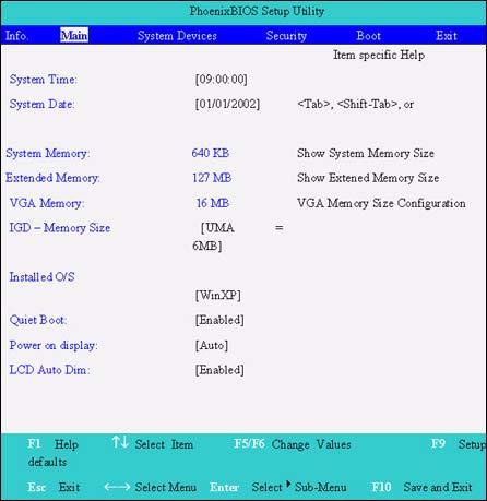
The Main screen displays a summary of your computer hardware information, and also includes basic setup parameters. It allows the user to specify standard IBM PC AT system parameters.
NOTE: The screen above is for reference only. Actual values may differ.
The table below describes the parameters in this screen. Settings in boldface are the default and suggested parameter settings.
Parameter Description Format/Option
System Time Sets the system time. Format: HH:MM:SS (hour:minute:second) System Time System Date Sets the system date. Format MM/DD/YYYY (month/day/ year) System Date
System Memory This field reports the memory size of the system. Memory size is fixed to 640MB Extended Memory This field reports the memory size of the extended memory in the system. Extended Memory size=Total memory size-1MB VGA Memory Shows the VGA memory size. The default value is set to 16MB Option:1/4/8/16/32MB
Quiet Boot Determines if Customer Logo will be displayed or not; shows Summary Screen is disabled or enabled. Enabled: Customer Logo is displayed, and Summary Screen is disabled. Disabled: Customer Logo is not displayed, and Summary Screen is enabled. Internal Hard Disk Shows the hard disk types and capacity. If there is no hard disk present or unknown type, “None” should be shown on this field, otherwise the capacity must be shown. Power on display Auto: During power process, the system will detect if any display device is connected on external video port. If any external display device is connected, the power on display will be in CRT (or projector) only mode. Otherwise it will be in LCD only mode. Both: Simultaneously enable both the integrated LCD screen and the system’s external video port (for an external CRT or projector). LCD Auto Dim Determines if the system will automatically dim the LCD brightness in order to save power when AC is not present. Option: Enabled or Disabled
Option: Auto or Both
Option: Enabled or Disabled
NOTE: The sub-items under each device will not be shown if the device control is set to disable or auto. This is because the user is not allowed to control the settings in these cases.
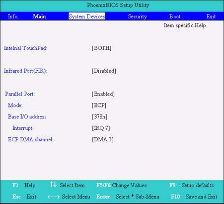
The System Devices screen contains parameters involving your hardware devices. It also provides advanced settings of the system.
The table below describes the parameters in the screen. Settings in boldface are the default and suggested parameter settings.
Parameter Description Options
Internal Touchpad Determines whether or not to disable the internal pointing device as the PS/2 mouse is connected. Both or Auto
Infrared Port (FIR) Enables, disables or auto detects the infrared port. Enabled/Disabled/Auto Parallel Port Enables, disables or auto detects the parallel port. Enabled/Disabled/Auto Mode Sets the operation mode of the parallel port. ECP, EPP, Normal or Bi-directional Base I/O address Sets the I/O address of the parallel port. This parameter is enabled only if Mode is set to ECP or Bi-directional. 378h/278h Interrupt Sets the interrupt request of the parallel port. IRQ7 or IRQ5 DMA Channel Sets a DMA channel for the printer to operate in ECP mode. This parameter is enabled only if Mode is set to ECP. DMA3 or DMA1
The Security screen contains parameters that help safeguard and protect your computer from unauthorized use.
The table below describes the parameters in this screen. Settings in boldface are the default and suggested parameter settings.
NOTE: When you are prompted to enter a password, you have three tries before the system halts. Don’t forget your password. If you forget your password, you may have to return your notebook computer to your dealer to reset it.
Setting a Password
Follow these steps as you set the user or the supervisor password: 1. Use the w andy keys to highlight the Set Supervisor Password parameter and press the e key. The Set Supervisor Password box appears:

Parameter Description
Option
User Password is Shows the setting of the uer password. Clear or Set Supervisor Password is Shows the setting of the administrator password Clear or Set Set User Password Press Enter to set the user password. When set, this password protects the BIOS Setup Utility from unauthorized access. Set Supervisor Password Press Enter to set the administrator password. When set, this password protects the BIOS Setup Utility from unauthorized access. Password on boot Allows the user to specify whether or not a password is required to boot. Disabled or Enabled
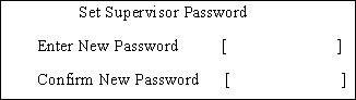
2. Type a password in the “Enter New Password” field. The password length can not exceeds 8 alphanumeric characters (A-Z, a-z, 0-9, not case sensitive). Retype the password in the “Confirm New
Password” field.
IMPORTANT:Be very careful when typing your password because the characters do not appear on the screen. 3. Press e. After setting the password, the computer sets the User Password parameter to “Set”. 4. If desired, you can opt to enable the Password on boot parameter. 5. When you are done, press u to save the changes and exit the BIOS Setup Utility.
Removing a Password
Follow these steps: 1. Use the w and y keys to highlight the Set Supervisor Password parameter and press the e key. The Set Password box appears:

2. Type the current password in the Enter Current Password field and press e. 3. Press e twice without typing anything in the Enter New Password and Confirm New Password fields.
The computer then sets the Supervisor Password parameter to “Clear”. 4. When you have changed the settings, press u to save the changes and exit the BIOS Setup Utility.
Changing a Password
1. Use the w and y keys to highlight the Set Supervisor Password parameter and press the e key. The Set Password box appears:
3. Type a password in the Enter New Password field. Retype the password in the Confirm New Password field. 4. Press e. After setting the password, the computer sets the User Password parameter to “Set”. 5. If desired, you can enable the Password on boot parameter. 6. When you are done, press u to save the changes and exit the BIOS Setup Utility.
If the verification is OK, the screen will display as following.

The password setting is complete after the user presses u. If the current password entered does not match the actual current password, the screen will show you the Setup Warning.

If the new password and confirm new password strings do not match, the screen will display the following message.

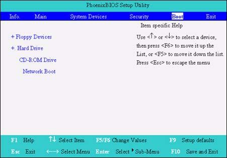
This menu allows the user to decide the order of boot devices to load the operating system. Bootable devices includes the distette drive in module bay, the onboard hard disk drive and the CD-ROM in module bay.
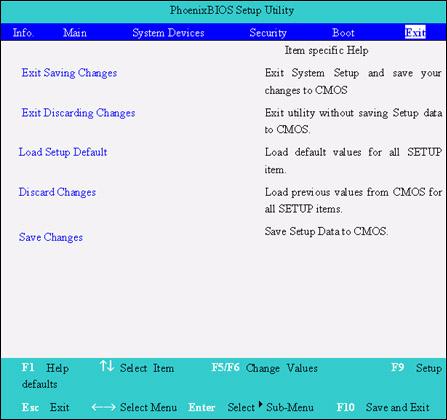
The Exit screen contains parameters that help safeguard and protect your computer from unauthorized use.
The table below describes the parameters in this screen.
Parameter Description
Exit Saving Changes Exit System Setup and save your changes to CMOS. Exit Discarding Changes Exit utility without saving setup data to CMOS. Load Setup Default Load default values for all SETUP item. Discard Changes Load previous values from CMOS for all SETUP items. Save Changes Save Setup Data to CMOS.
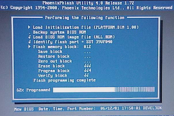
The BIOS flash memory update is required for the following conditions: New versions of system programs New features or options Restore a BIOS when it becomes corrupted. Use the Phlash utility to update the system BIOS flash ROM. NOTE: If you do not have a crisis recovery diskette at hand, then you should create a Crisis Recovery Diskette before you use the Phlash utility. NOTE: Do not install memory-related drivers (XMS, EMS, DPMI) when you use the Phlash. NOTE: Please use the AC adaptor power supply when you run the Phlash utility. If the battery pack does not contain enough power to finish BIOS flash, you may not boot the system because the BIOS is not completely loaded. Fellow the steps below to run the Phlash. 1. Prepare a bootable diskette. 2. Copy the Phlash utilities to the bootable diskette. 3. Then boot the system from the bootable diskette. The Phlash utility has auto-execution function.
System Diagnostic Diskette
This diagnostic diskette is for the Acer TravelMate 530 series notebook machine. You can find the utility in Service CD kit. It provides the following functions: 1. BIOS Re-flash 2. Serial port, parallel port and FDD test 3. CMOS RTC and FDD Test 4. Thermal Test 5. Config Test 6. 1394ID Check 7. Touchpad Test 8. VGA R.G.B. Mode Test 9. FAN Test 10. Keyboard Test 11. 32bit Systemcard Test 12. Audio Test 13. Battery Charge Test To use the diagnostic programs, and system utilities, first create a bootable diskette. Then copy the files under the following directory: Model1/field/files/Diagnostic Utility on this service CD. After you copy all files under the Diagnostic Utility folder, then boot the system from the diagnostic diskette you create. Important! 1.) Please insert this service CD as you use the diagnostic diskette. 2.) Please insert a music CD when you go through Audio Test. Play the music CD during the test to see if the speaker emits sounds or not. NOTE: This program contains a readme.txt file. This readme.txt file will introduce each test utility and its functions.
IMPORTANT: 1The diagnostics program we use for TravelMate 530 series is not exactly the same as PQA (Product Quality Assurance), the diagnostic program we used to employ in other model. The system diagnostic utilities is provided by Acer Headquarters. You can utilize it as a basic diagnostic tool. To
get this program, find it in the TravelMate 530 series service CD kit. To better fit local service requirements, your regional office MAY have other diagnostic program. Please contact your regional offices or the responsible personnel/channel to provide you with further technical details. NOTE: For ASSY Function Test Procedure, please prepare the following items for system components test: SIO/PIO loopback, diskette, mouse (PS/2), CD-Disk (Test Program), battery pack, SYS_card (Card Bus)X2, AC-adapter, keyboard, external speaker and feather.
1. BIOS Re-flash Insert CD-Disk and floppy disk then boot from floppy disk drive to BIOS re-flash.
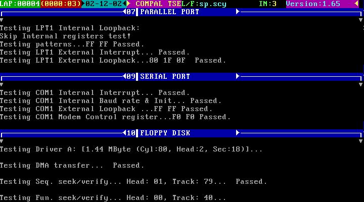
2. Serial Port, Parallel Port and FDD Test Insert SIO/PIO loopback to serial/parallel port. Place the diskette in the floppy diskette drive. Then run the test utility.
3. CMOS RTC and FDD Test Insert the diskette to the floppy disk drive for test.
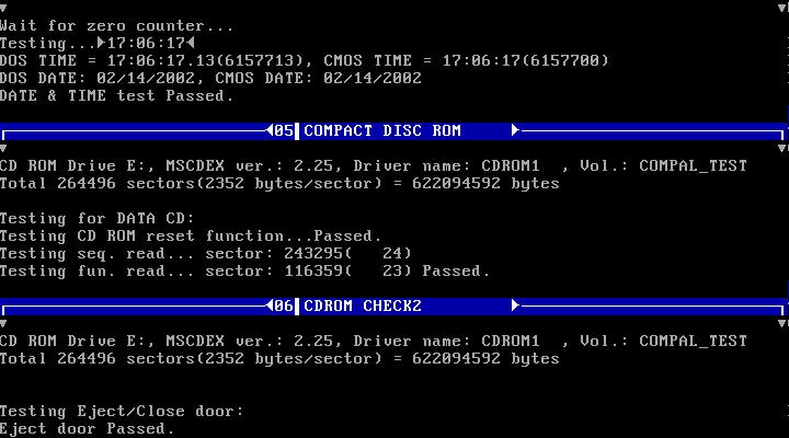
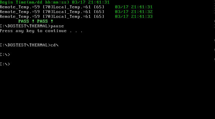
4. Thermal Test
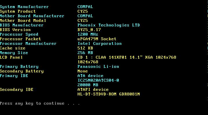
5. Config Test
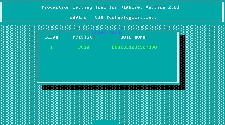
6. 1394 ID Check If you need to confirm whether the 1394GUID serial number has been input or not, you can run this utility. Press^then Y key to next test.
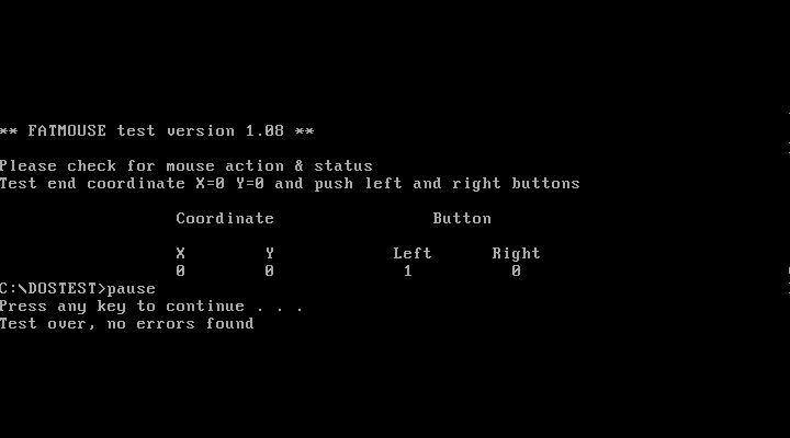
7. Touchpad Test After you run the utility, please point and move your finger on the touchpad. Then see if the movement of the cursor can reach to left top (X=0, Y=0). Press the right and left button then continue next test.
8. VGA R.G.B. Mode Test Inspects red, green and blue color of display quality. Press any key to continue next test.

9. FAN Test Check if the fan has turned on or not. You can confirm the function by a feather.

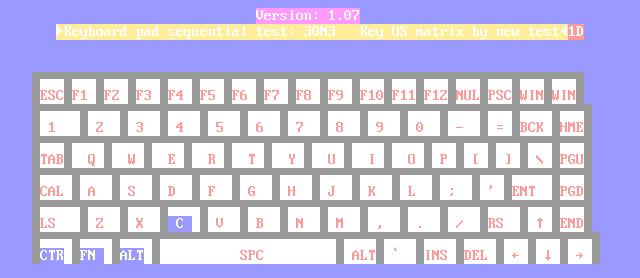
10. Keyboard Test Press all keys according to this order--from left to right and from up to down to test each key’s function. If pass then press b + Break to continue the next test.
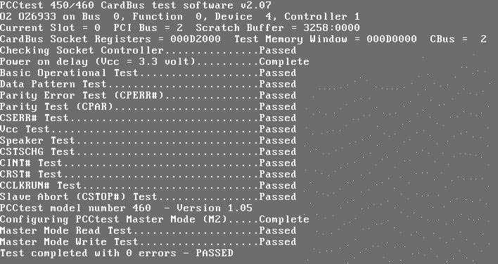
11. 32bit Systemcard Test Insert two pieces of Syscard (Card bus) into PCMCIA slots for test.
12. Audio Test Test the left channel first. After you hear a sound presseto test the right channel.


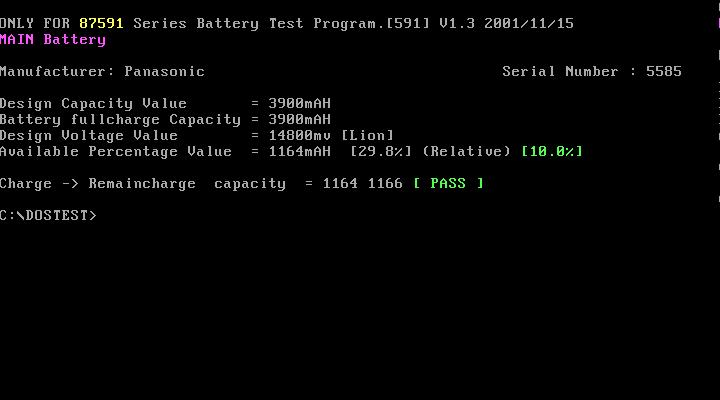
13. Battery Charge Test Plug in AC adapter to the system for test.