1 minute read
Remove the Daughter Board


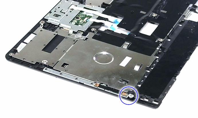
8. See “Removing the Middle Cover” on page 64. 9. See “Removing the Keyboard” on page 65. 10. See “Removing the LCD Module” on page 66. 11. See “Separating the Upper Case from the Lower Case” on page 70. 12. Remove the screw (G) on the LED indicators board.
Step Size (Quantity) Color Torque
1 M2 x L3 (1) Silver 1.6 kgf-cm
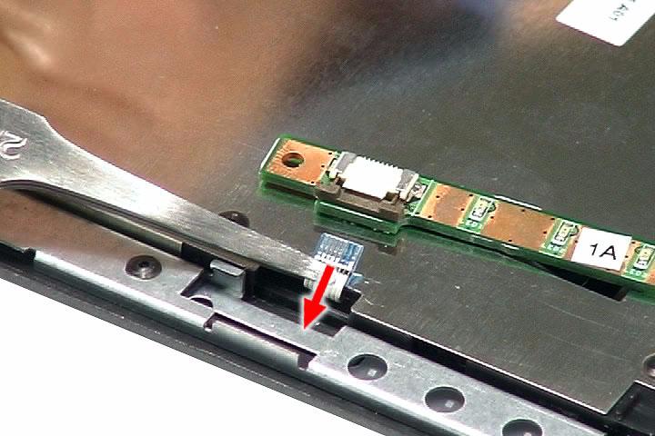
13. Turn the LED board over, then detach the LED cable from the board.

14. Disconnect the LED board cable from the board, then remove the board.

1. See “Removing the Battery Pack” on page 51. 2. See “Removing the SD Dummy Card” on page 51. 3. See “Removing the Express Dummy Card” on page 52. 4. See “Removing the Lower Cover” on page 53. 5. See “Removing the Fan Module” on page 60. 6. See “Removing the CPU Heatsink Module” on page 61.
7. See “Removing the CPU” on page 62. 8. See “Removing the Middle Cover” on page 64. 9. See “Removing the Keyboard” on page 65. 10. See “Removing the LCD Module” on page 66. 11. See “Separating the Upper Case from the Lower Case” on page 70. 12. Disconnect the Bluetooth board cable from the mainboard.

13. Disconnect the speaker cable from the mainboard.

14. Remove the two screws (C) that secures the daughter board to the mainboard.

Step Size (Quantity) Color Torque 1~4 M2 x L3 (2) Silver 1.6 kgf-cm

