7 minute read
Disassembly Procedure


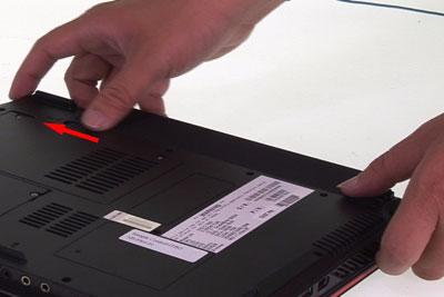
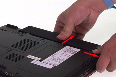
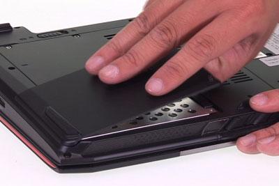
Removing the Battery Pack
1. Unlock the battery lock to the end as the arrow indicates. 2. Slide the battery latch to the end and hold it. Then remove the battery pack.
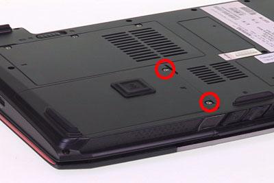
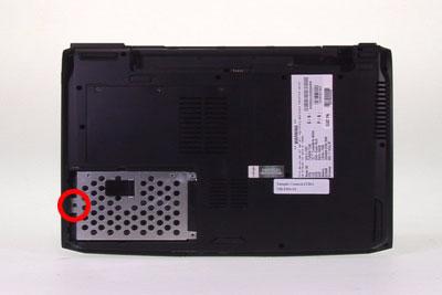
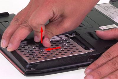
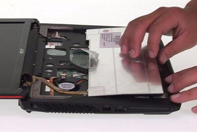
Removing the HDD Module
1. Release the two screws fastening the HDD module cover. 2. Detach the HDD module cover. 3. Release the screw securing the HDD module. 4. Pull the HDD module then lift the HDD module as the arrow indicates.
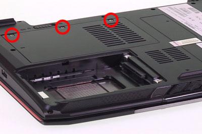
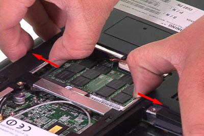
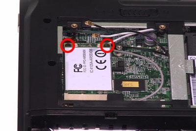
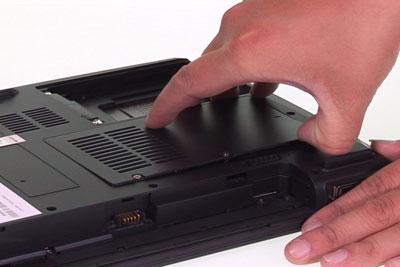
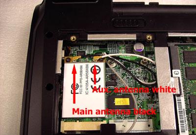
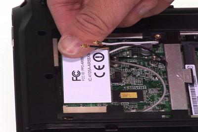
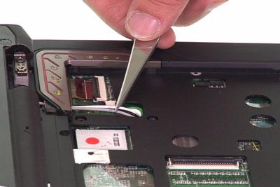
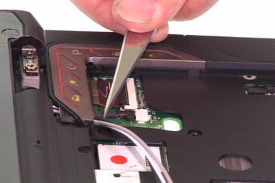
1. Release the three screws holding the RAM and Mini PCI card cover. 2. Then remove the cover. 3. Press the RAM module locks at the same time as the arrows indicate. The RAM module will pop up then detach it. Repeat this step to detach another RAM module. 4. Disconnect the main and the auxiliary antennae. The main antenna is black and the auxiliary antenna is white. The gray cable is protected by a plastic cover and serves for nothing in this model. 5. Release the two screws holding the Mini PCI card. 6. The Mini PCI card will pop up then detach it.
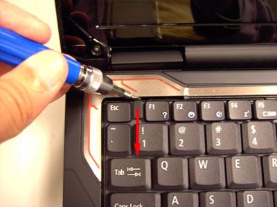
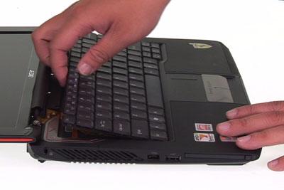
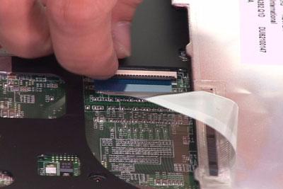
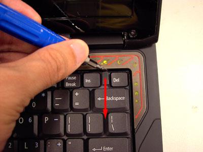
1. Release the left latch securing the keyboard plate. 2. Release the right latch securing the keyboard plate. 3. Carefully detach the keyboard plate and place the keyboard plate as shown. 4. Release the keyboard FFC lock carefully because it is fragile. Then detach the keyboard plate.
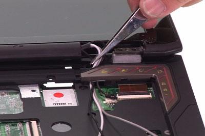
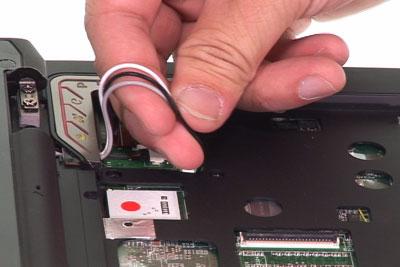
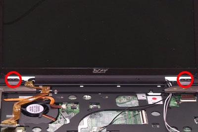
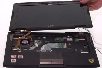
After removing the keyboard plate, please follow the steps below to remove the LCD module. 1. Slightly pull out the main and the auxiliary antennae and the gray cable. 2. Disconnect the microphone cable. 3. Release the four screws holding the LCD module. 4. Slightly pull out the four cables then remove the LCD module.
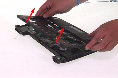
Separating the Upper Case and the Lower Case
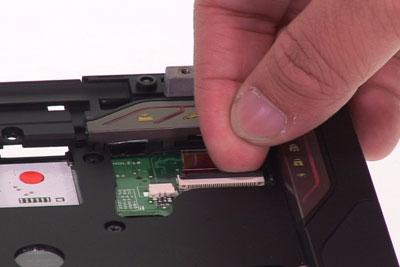
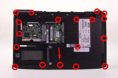
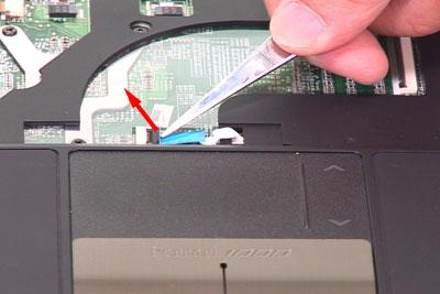
1. Carefully release the button board FFC lock then disconnect the button board FFC. 2. Slightly release the click button board FFC lock then disconnect the click button board FFC. 3. Release the power button board lock then disconnect the power button board FFC. 4. Release the five screws securing the upper case and the lower case on the upper side. 5. Release the 18 screws securing the upper case and the lower case on the bottom side. The screw indicated by arrow is under the rubber cushion so you have to remove the rubber cushion at first. 6. Then detach the upper case from the main unit.
1. Disconnect the Bluetooth module cable. 2. Release the screw holding the Bluetooth module then detach the Bluetooth module.
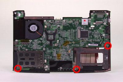
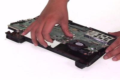
Removing the Main Board
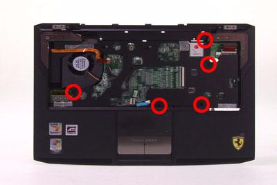
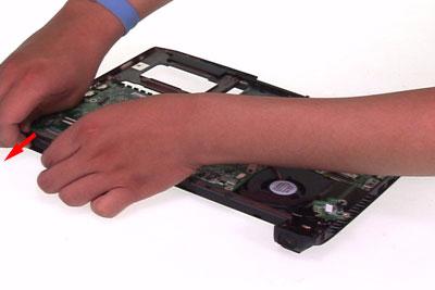
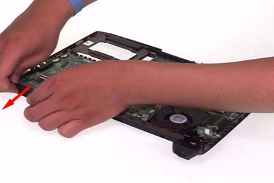
1. Disconnect the speaker cable. 2. Slightly pull the edge of the lower case as the arrow indicates because the DC board is stuck by the edge of the lower case. Then detach the DC board from the lower case. 3. Release the three screws securing the main board. 4. Slightly pull the edge of the lower case as the arrow indicates because the main board is stuck by the edge of the lower case. Then detach the main board.
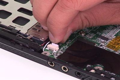
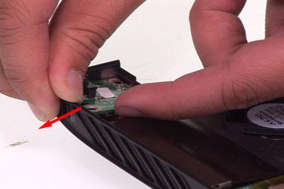
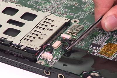
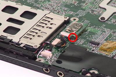
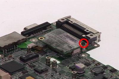
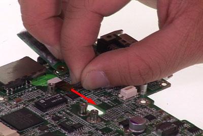
Removing the Modem Board
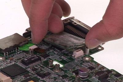
1. Release the screw holding the modem board. 2. Detach the modem board from the main board and disconnect it.
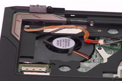
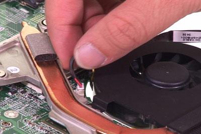
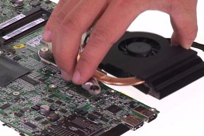
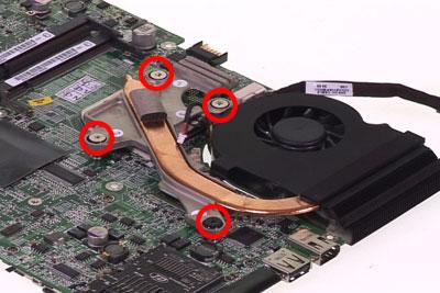
1. Slightly disconnect the system fan cable. 2. Release the four screws holding the thermal module then detach the thermal module. 3. Disconnect the DC board cable.
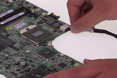
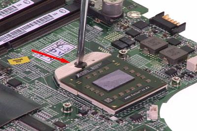
Removing the CPU
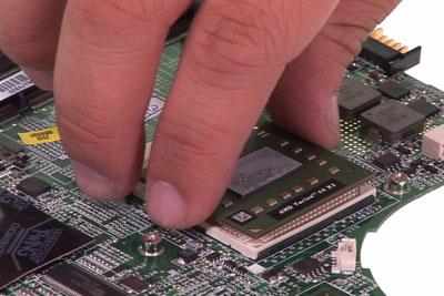
1. Release the screw securing the CPU by turning the flat-headed screw driver counter clockwise. 2. Then carefully detach the CPU from the socket.
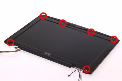
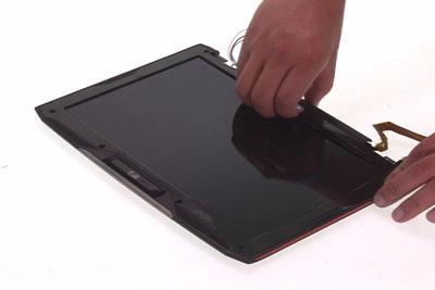
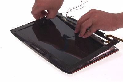
Removing the LCD Bezel
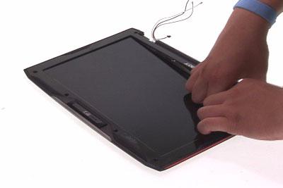
1. Detach the mylars covered on screws then release the six screws securing the LCD bezel. 2. Carefully detach the LCD bezel from the LCD module as shown till the LCD bezel is total removed.
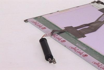
Removing the Inverter Board
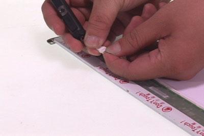
1. Carefully disconnect the LVDS cable. 2. Carefully disconnect the LCD cable then remove the inverter board.
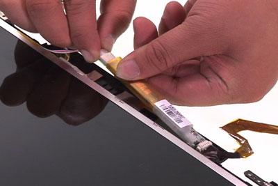
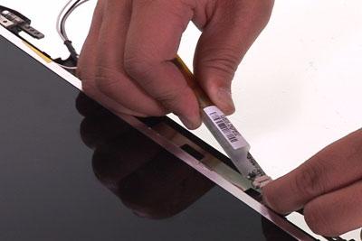
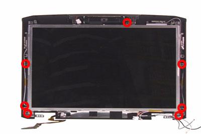
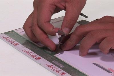
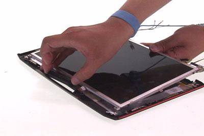
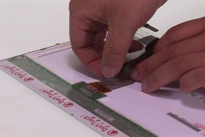
1. Release the seven screws securing the LCD panel and the CCD module. 2. Then remove the LCD panel and the CCD module together. 3. Put the LCD panel and the CCD module on a flat and stable surface. 4. Carefully disconnect the CCD module. 5. Tear off the tape holding the LCD cable. 6. Carefully pull and disconnect the LCD cable.
NOTE: When you remove the CCD module and the LCD cable, please do not press the LCD panel.
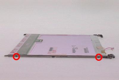
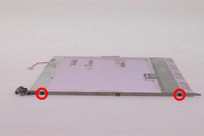
1. Release the four screws securing the left and the right LCD brackets. 2. Then remove the left and the right LCD brackets.
Troubleshooting
Please use the following procedures as a guide for computer problems.
NOTE: The diagnostic tests are intended to test only Acer products. Non-Acer products, prototype cards, or modified options may occur errors or invalid responses. 1. Obtain the detailed fail symptoms as many as possible. 2. Verify the symptoms by attempting to recreate, running the diagnostic tests or repeating the same operation.


