1 minute read
System Block Diagram and Board Layout


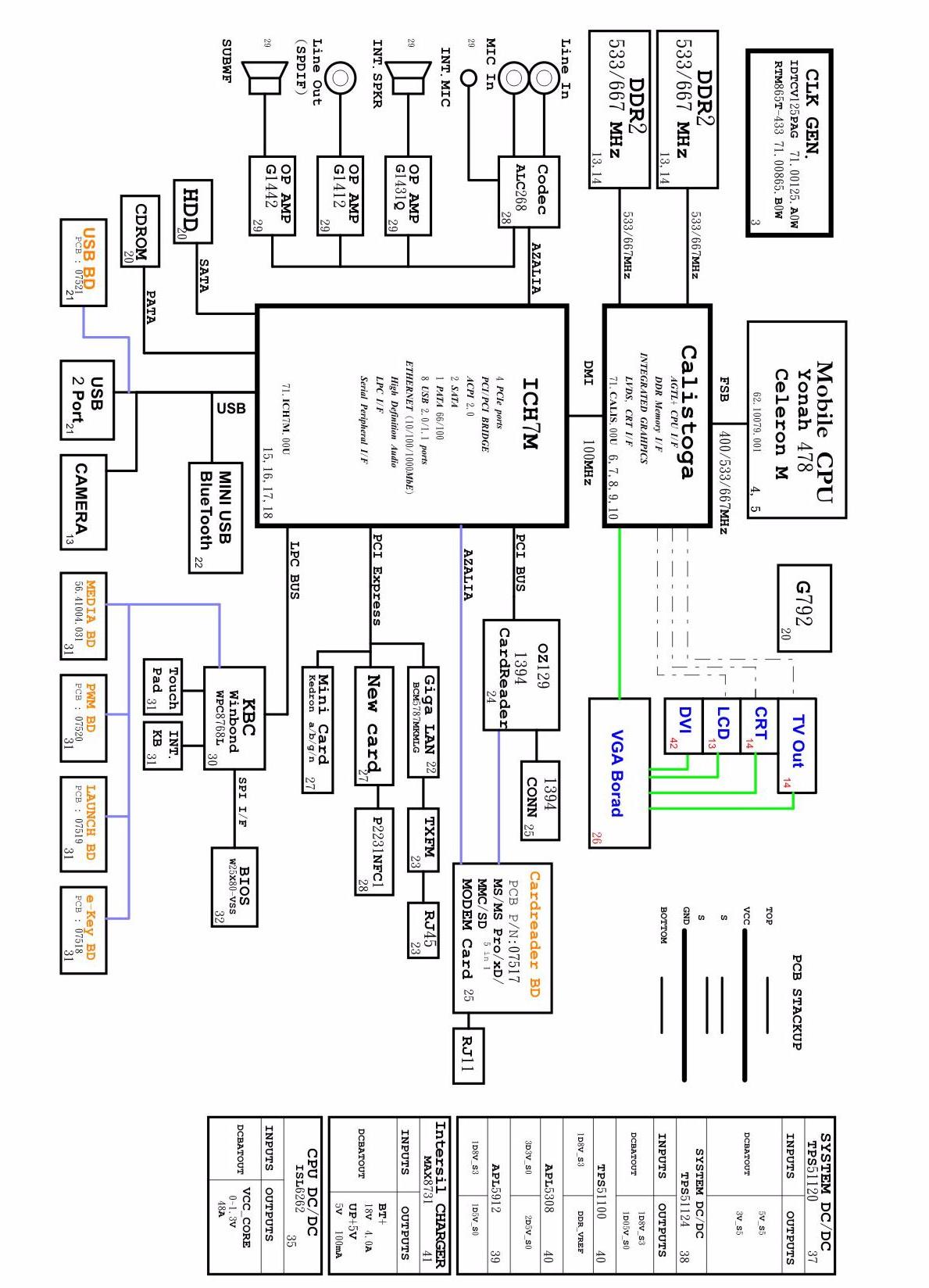
System Block Diagram
This section shows the top and bottom layout of the Aspire 5910 system board.
Top View
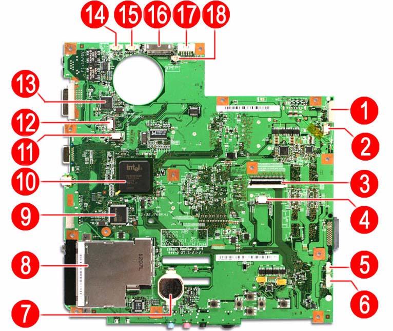
Item Code Description Item Code
Description
1 USBCN1 USB FPC cable connector 10 U14 Intel ICH7-M (south bridge) 2 MEDIA1 Media FPC cable connector 11 LAUNCHCN1Launch board cable connector 3 KB1 Keyboard cable connector 12 PWRCN1 Power FPC cable connector 4 TPAD1 Touchpad board cable connector 13 U4 BCM5787M Gigabit Ethernet controller 5 SPKR2 Subwoofer cable connector 14 INTMIC1 Microphone cable connector 6 BLUE1 Bluetooth board cable connector 15 SPKR1 Speaker cable connector 7 RTC1 CMOS battery (RTC battery) 16 LCD1 LCD-CCD cable connector 8 NEW1 Card reader slot 17 DC1 DC-in cable connector 9 U15 IEEE 1394/card reader function chip 18 E_KEY1 E-key board cable connector
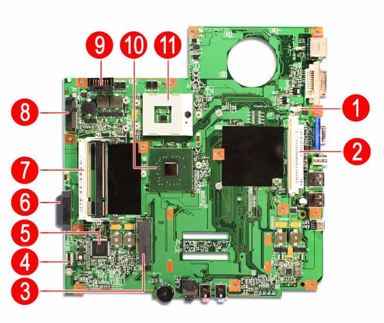
Item Code Description Item Code
Description
1 FAN1 Fan cable connector 7 DMI soDIMM slots 2 MXM1 VGA board slot 8 MINI1 WLAN board slot 3 CARD READER1 Card reader board connector 9 BAT1 Battery pack connector 4 U47 Keyboard controller 10 U40 Intel MCH (north bridge) 5 SATA1 Hard drive connector 11 U36 Intel LGA775 socket 6 ODD1 Optical drive connector
If you have enabled the Password on Boot field and you forget the supervisor password, you will not be able to boot up the computer. The same thing applies if you forget an HDD password. Your Aspire notebook has a hardware dip switch (SW1) for clearing lost system passwords. Go to page 18 for instructions on how to use this dip switch.
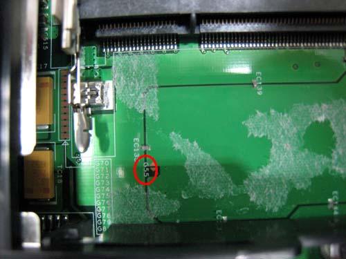
PSW_CLR# 1 G55
2
GAP-OPEN