1 minute read
Removing the Upper Cover


Step
Size
ODD Bracket M2.0*3L 2
Quantity Screw Type
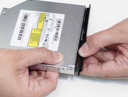
5. Remove the ODD bezel by rotating the top edge downward and pulling it clear of the module.
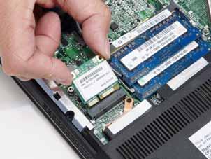
1. See “Removing the Lower Cover” on page 49. 2. Push out the release latches on both sides of the DIMM socket to release the DIMM module.
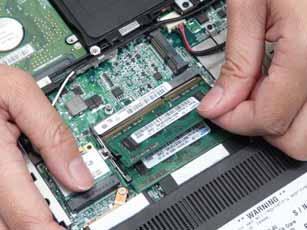
3. Remove the DIMM module.
4. Repeat steps for the second DIMM module if present.
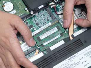
1. See “Removing the Lower Cover” on page 49. 2. Disconnect the two (2) antenna cables from the WLAN Board and remove the one (1) screw to release the
WLAN Board.
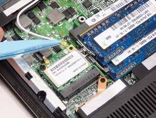
NOTE: Cable placement is Black to the TR1 terminal (left) and White to the TR2 terminal (right).
Step
Size
WLAN Board M2.0*3 1
Quantity Screw Type
3. Detach and remove the WLAN Board from the WLAN socket.