1 minute read
REMOVING/REFITTING THE SUSPENSION CYLINDER20.25SI............................................................................D2


Description
77 Screw. 78 Nut. 79 Thrust bearing. 80 Screw. 81 Nut. 82 Screw. 83 Cylinder pin. 84 Cylinder. 85 Circlip. 86 Washer. 87 Seal. 88 Washer. 89 Grease nipple. 90 Washer. 91 Seal. 92 Hydraulic coupling.
Suspension cylinder and lower arm
93 Lower arm. 94 Steering stop. 95 Screw. 96 Pin. 97 Grease nipple. 98 Screw. 99 Seal. 100 Bush. 101 Bush. 102 Washer. 103 Seal. 104 Nut. 105 Seal. 106 Front flange. 107 Screw. 108 Bush. 109 Screw. 110 Plug. 111 Circlip. 112 Cover. 113 Rear flange. 114 Lock screw. 115 Nut. 116 Torsion bar. 117 O-ring. 118 Pin. 119 Seal. 120 Washer. 121 Bush. 122 Seal.
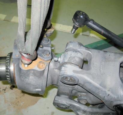
Removing/refitting the suspension cylinder20.25SI
–Immobilise the tractor (see "Preliminary operations prior to working on the front axle"). –Sling the assembly on the level of the wheel pivot. –Remove the axis (48), (see removal of the upper arm 20.25SI). –Remove the axis (96), (see removal of the lower arm 20.25SI) –Clear access to the lower part of the jack by lifting the assembly. –Remove the circlip(93). –Remove the lower part of the jack using a puller. –Proceed identically for the upper part after removing the stop ring (85). –To refit, apply the reverse sequence of removal.
452msm99
43
96 121 48
93
84
Fig.40