6 minute read
CHAPTER 6 ADJUSTMENTS A CAUTION


BEFORE proceeding to perform any adjust· ments on the Disc Mower, exercise the MAN· DATORY SAFETY SHUTDOWN PROCEDURE (page 8) BEFORE proceeding.
DRIVE BELT TENSION (Figs. 6-1
& 6-2)
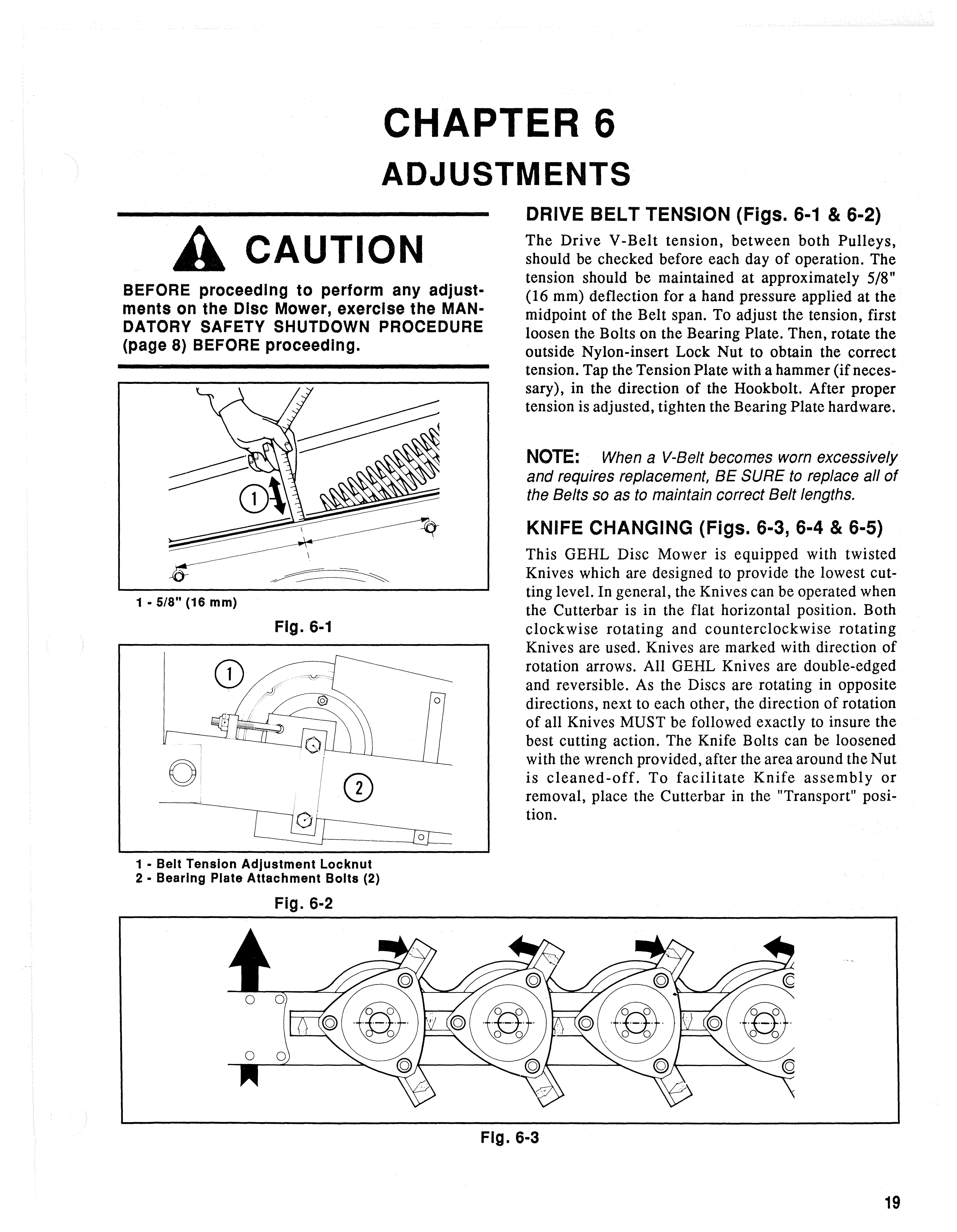
The Drive V -Belt tension, between both Pulleys, should be checked before each day of operation. The tension should be maintained at approximately 5/8" (16 mm) deflection for a hand pressure applied at the midpoint of the Belt span. To adjust the tension, first loosen the Bolts on the Bearing Plate. Then, rotate the outside Nylon-insert Lock Nut to obtain the correct tension. Tap the Tension Plate with a hammer (ifnecessary), in the direction of the Hookbolt. After proper tension is adjusted, tighten the Bearing Plate hardware.
NOTE: When a V-Belt becomes worn excessively and requires replacement, BE SURE to replace all of the Belts so as to maintain correct Belt lengths.
KNIFE
CHANGING (Figs.
6-3, 6-4 & 6-5)
This GEHL Disc Mower is equipped with twisted Knives which are designed to provide the lowest cutting level. In general, the Knives can be operated when the Cutterbar is in the flat horizontal position. Both clockwise rotating and counterclockwise rotating Knives are used. Knives are marked with direction of rotation arrows. All GEHL Knives are double-edged and reversible. As the Discs are rotating in opposite directions, next to each other, the direction of rotation of all Knives MUST be followed exactly to insure the best cutting action. The Knife Bolts can be loosened with the wrench provided, after the area around the Nut is cleaned-off. To facilitate Knife assembly or removal, place the Cutterbar in the "Transport" position.
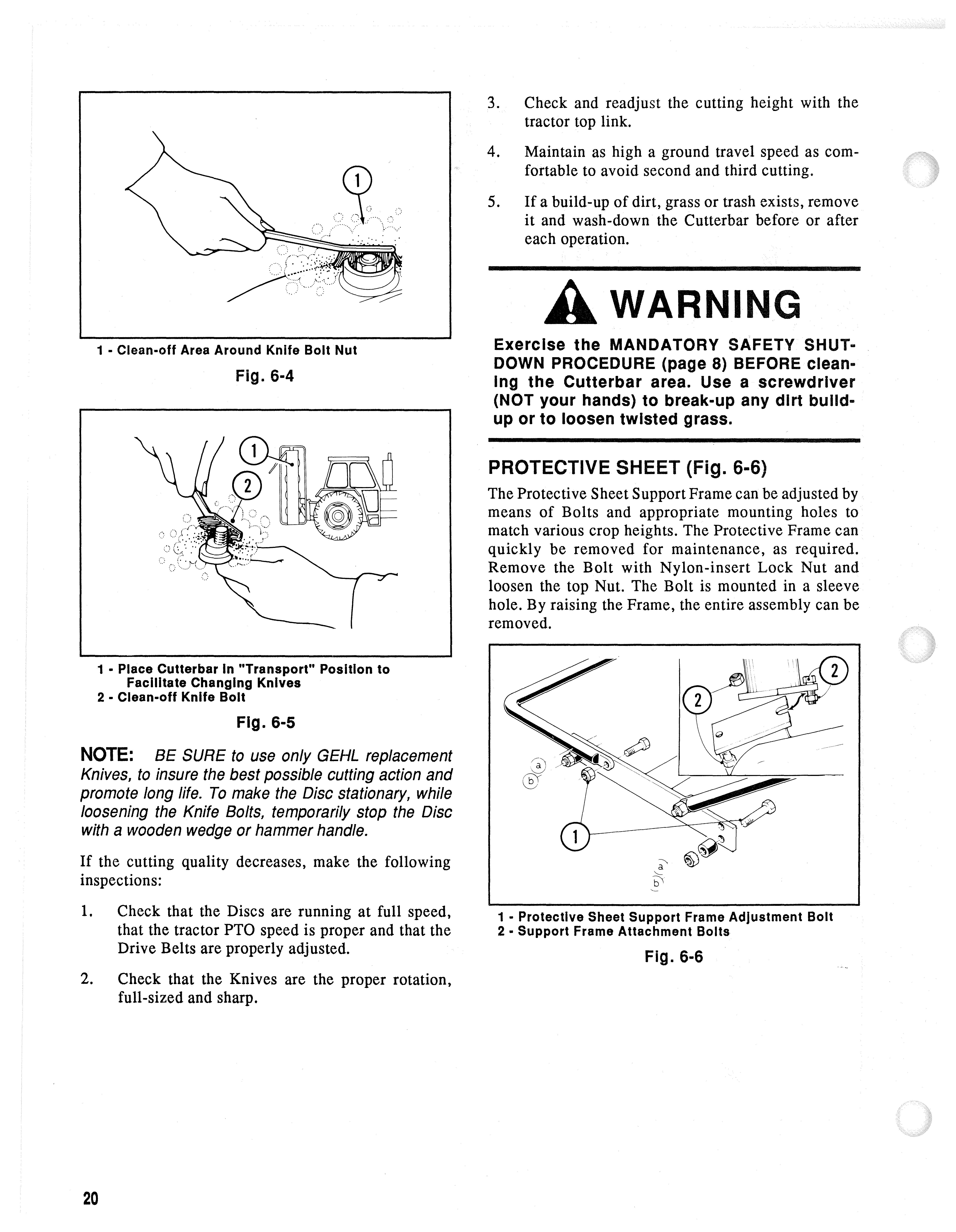
1 - Clean-off Area Around Knife Bolt Nut
Fig. 6-4
3. Check and readjust the cutting height with the tractor top link.
4. Maintain as high a ground travel speed as comfortable to avoid second and third cutting.
5. lf a build-up of dirt, grass or trash exists, remove it and wash-down the Cutterbar before or after each operation.
Awarning
Exercise the MANDATORY SAFETY SHUTa DOWN PROCEDURE (page 8) BEFORE cleanIng the Cutterbar area. Use a screwdriver (NOT your hands) to break-up any dirt buildup or to loosen twisted grass.
PROTECTIVE SHEET (Fig. 6-6)
The Protective Sheet Support Frame can be adjusted by means of Bolts and appropriate mounting holes to match various crop heights. The Protective Frame can quickly be removed for maintenance, as required. Remove the Bolt with Nylon-insert Lock Nut and loosen the top Nut. The Bolt is mounted in a sleeve hole. By raising the Frame, the entire assembly can be removed.
1 - Place Cutter bar In "Transport" Position to Facilitate Changing Knives
2 - Clean-off Knife Bolt
Fig. 6-5 lf the cutting quality decreases, make the following inspections:
NOTE: BE SURE to use only GEHL replacement Knives, to insure the best possible cutting action and promote long life. To make the Disc stationary, while loosening the Knife Bolts, temporarily stop the Disc with a wooden wedge or hammer handle.
1. Check that the Discs are running at full speed, that the tractor PTO speed is proper and that the Drive Belts are properly adjusted.
2. Check that the Knives are the proper rotation, full-sized and sharp.
1 - Protective Sheet Support Frame Adjustment Bolt
2 • Support Frame Attachment Bolts
Fig. 6-6
Chapter 7
MAINTENANCE & SERVICE A CAUTION
BEFORE proceeding to perform ALL service and maintenance routines on this unit, exercise the MANDATORY SAFETY. SHUTDOWN PROCEDURE (page 8).
HARDWARE (Fig. 7-1)
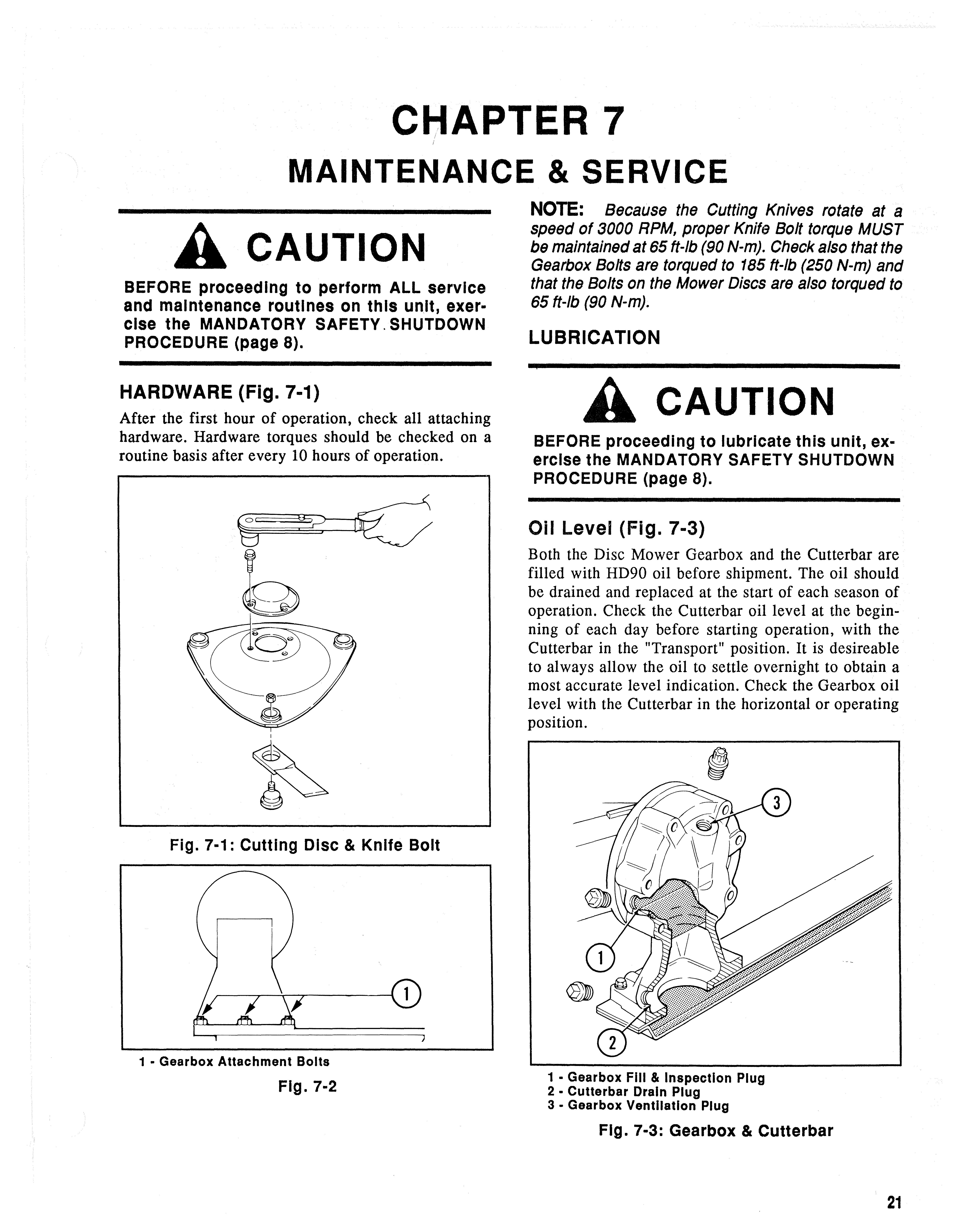
After the first hour of operation, check all attaching hardware. Hardware torques should be checked on a routine basis after every 10 hours of operation.
NOTE: Because the Cutting Knives rotate at a speed of 3000 RPM, proper Knife Bolt torque MUST be maintained at 65 ft-Ib (90 N-m). Check also that the Gearbox Bolts are torqued to 185 ft-Ib (250 N-m) and that the Bolts on the Mower Discs are also torqued to 65 ft-Ib (90 N-m).
Lubrication A Caution
BEFORE proceeding to lubricate this unit, exercise the MANDATORY SAFETY SHUTDOWN PROCEDURE (page 8).
Oil Level (Fig. 7-3)
Both the Disc Mower Gearbox and the Cutterbar are filled with HD90 oil before shipment. The oil should be drained and replaced at the start of each season of operation. Check the Cutterbar oil level at the beginning of each day before starting operation, with the Cutterbar in the "Transport" position. It is desireable to always allow the oil to settle overnight to obtain a most accurate level indication. Check the Gearbox oil level with the Cutterbar in the horizontal or operating position.
Filling Plugs & Oil Contents (Fig. 7-4 & 7-5)
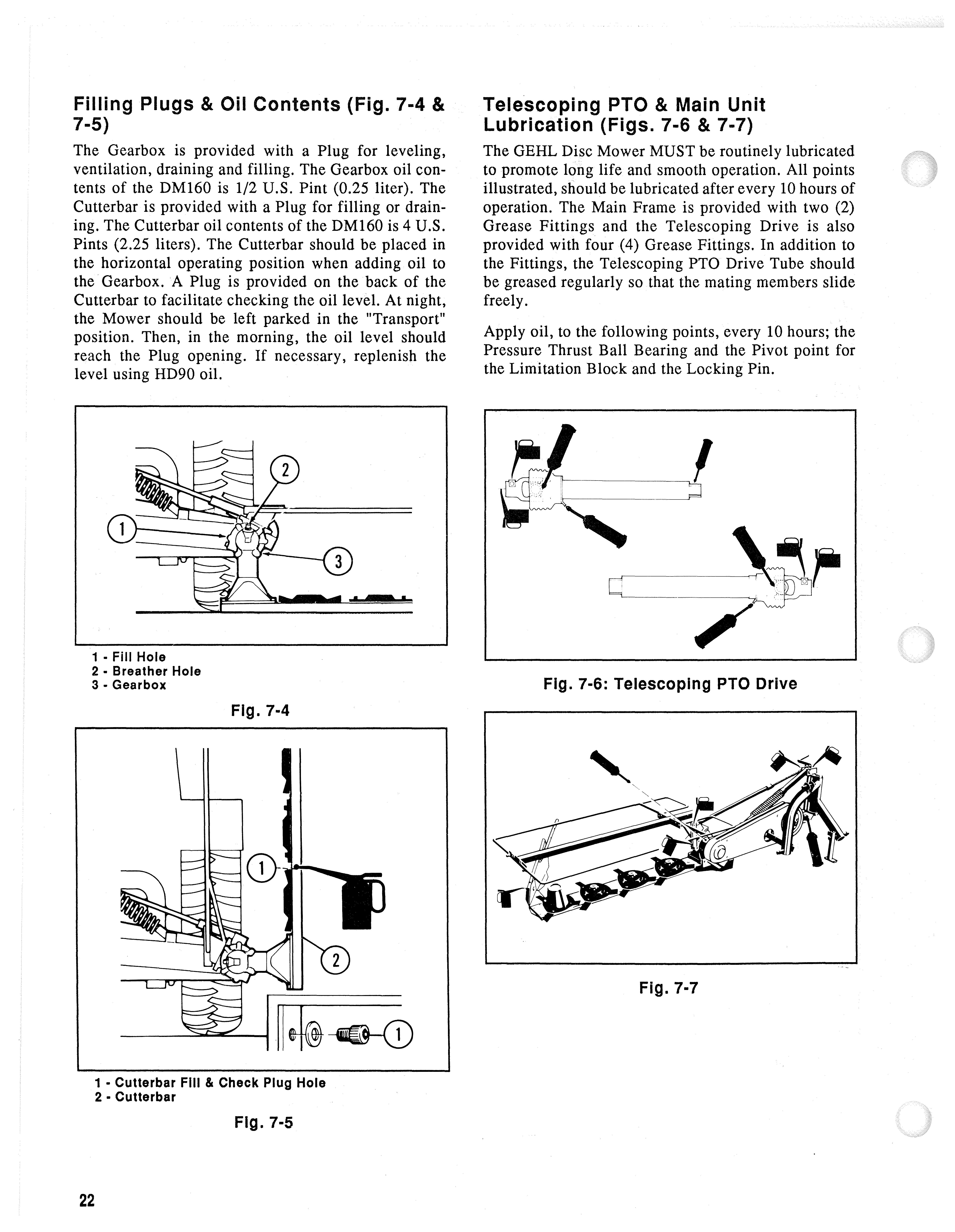
The Gearbox is provided with a Plug for leveling, ventilation, draining and filling. The Gearbox oil contents of the DM160 is 1/2 U.S. Pint (0.25 liter). The Cutterbar is provided with a Plug for filling or draining. The Cutterbar oil contents of the DM160 is 4 U.S. Pints (2.25 liters). The Cutterbar should be placed in the horizontal operating position when adding oil to the Gearbox. A Plug is provided on the back of the Cutterbar to facilitate checking the oil level. At night, the Mower should be left parked in the "Transport" position. Then, in the morning, the oil level should reach the Plug opening. If necessary, replenish the level using HD90 oil.
Telescoping PTO & Main Unit Lubrication (Figs. 7-6 & 7-7)
The GEHL Disc Mower MUST be routinely lubricated to promote long life and smooth operation. All points illustrated, should be lubricated after every 10 hours of operation. The Main Frame is provided with two (2) Grease Fittings and the Telescoping Drive is also provided with four (4) Grease Fittings. In addition to the Fittings, the Telescoping PTO Drive Tube should be greased regularly so that the mating members slide freely.
Apply oil, to the following points, every 10 hours; the Pressure Thrust Ball Bearing and the Pivot point for the Limitation Block and the Locking Pin.
Chapter 8
SET-UP & ASSEMBLY
Procedures established in these set-up instructions are given in a step-by-step manner, with various parts of the process listed in such a way as to make it possible for two people to do the sequence, without having to remove parts in order to make other component attachments. The Disc Mower is packed in two crates; one crate contains the Hitch and Lift Cylinder and the other crate contains the Cutterbar and Safety Frame.
Disc Mower set-up should be performed on a concrete floor, inside an enclosed workshop, which is equipped with the proper tools and an overhead hoist.
NOTE: The following abbreviations are used herein:
- Carriage Bolt
- Cap Screw (Hexagon Head)
- Hexagon Head Machine Screw
- Plow Bolt
- Round Head Machine Screw
- Screw
- Nut (Hexagon)
- Lock Nut (Hexagon)
- Nylon-insert Lock Nut
- Wing Nut
L - Lock (Washer)
P - Plain (Washer)
NPT - National Pipe Thread
Unless otherwise noted, the standard fastening procedure is to secure two parts with a CS, Land N. A part with a mounting slot should be secured with a P against the slotted surfaces. LN's are sometimes used to prevent two parts from separating but still to allow one part to move or rotate next to the other. Attaching hardware, which will require installation in the path of cut crop, should always be installed with the head of the screw on the same side of part which will be in contact with the material.
NOTE: Before proceeding, remove all components which are shipped in the two separate crates.
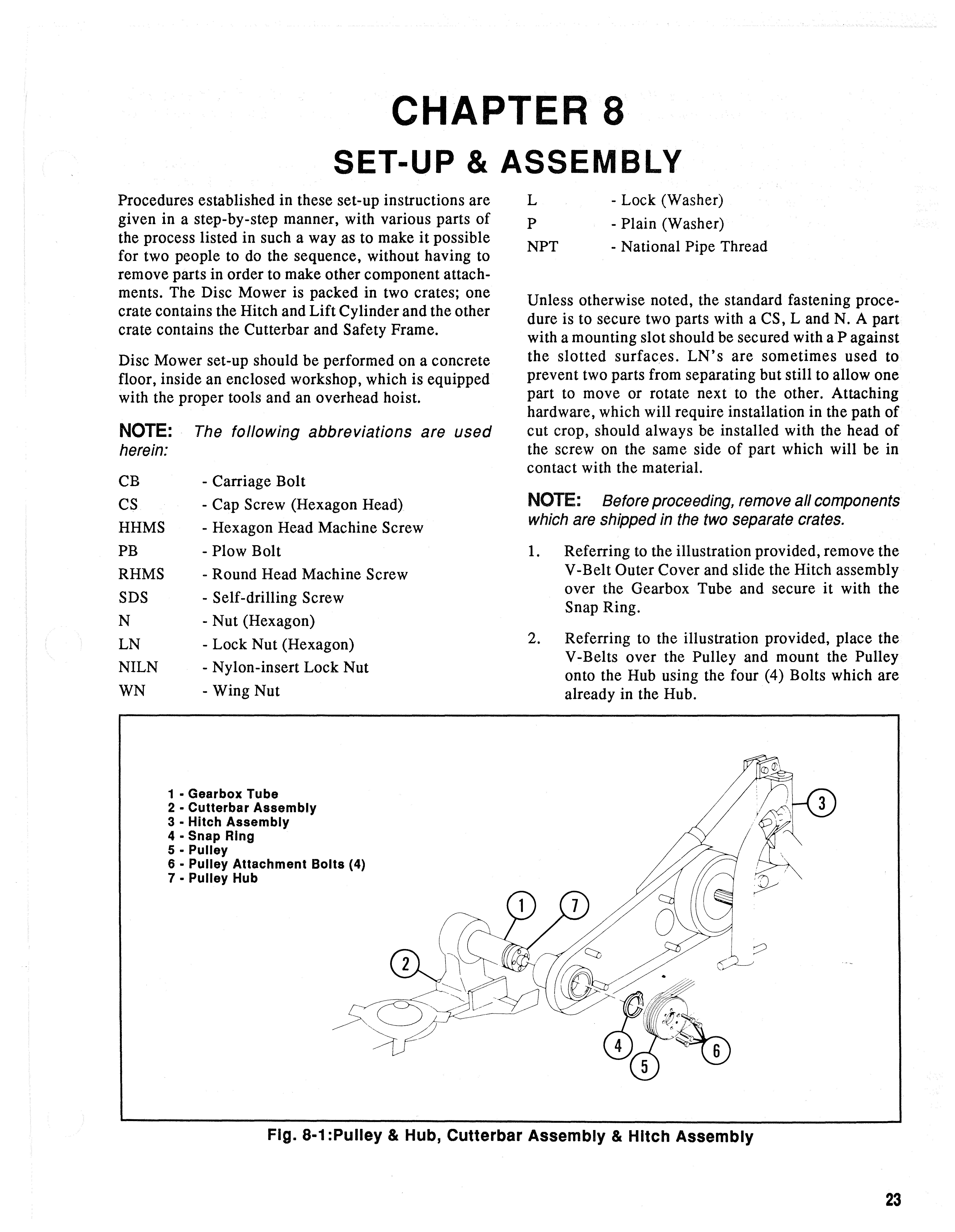
1. Referring to the illustration provided, remove the V-Belt Outer Cover and slide the Hitch assembly over the Gearbox Tube and secure it with the Snap Ring.
2. Referring to the illustration provided, place the V-Belts over the Pulley and mount the Pulley onto the Hub using the four (4) Bolts which are already in the Hub.
NOTE: The threaded holes in the Pulley are for pushing the Pulley off, when necessary.
3. Referring to the illustration provided, adjust the V-Belts tension for a 5/S" (16 mm) deflection for a hand pressure applied at the midpoint between the two Sheaves. Install and secure the Rubber Strip and V-Belt Outer Cover after proper tension is adjusted.
4. Refer to the photograph (Fig. 5-3, in chapter 5) and properly orient and attach the hydraulic Lift Cylinder.
5. Refer to the appropriate parts exploded-view drawing and properly orient and secure the Breakaway Shear Arm between the 3-Point Support Frame and the Drive Mechanism using the hardware provided.
6. Refer to the illustration provided and assemble the Frame for the Protective Cover in the following manner: a. Remove the long Bolts from the Gearbox and mount the Bracket onto the Gearbox. Then, install the Protective Cover Frame onto the Bracket making sure to use the Special Washer where shown. b. Properly orient and attach the Frame Wings. Make sure that the attaching hardware is left loose enough to allow the Frame Wings to be moved. c. Install the Height Adjustment Bolts with the Bushings so that the Cover is leveled.
7. Refer to the illustration provided and attach the Swathboard to the end of the Cutterbar with the Carriage Bolt, Spring, Washer and Locknut.
8. Properly orient and secure the Wooden Stick to the Swathboard with the Hooded Bolt and Cap Screw as shown. Secure each fastener with a Locknut.
9. Properly orient and attach the Protective Cover to the Mount by securing the Fastener Belts.
10. After the unit is completely set-up, check the oil levels in the Cutterbar and Gearbox. In addition, BE SURE to check that all mounting hardware is tightly secured.