7 minute read
CHAPTER 5 OPERATION


Emergency Shutdown A Caution
BEFORE starting the tractor engine and running the Disc Mower, review and comply with ALL SAFETY recommendations set forth In the SAFETY chapter of this mctnual.
In an emergency or in case material or a foreign object becomes lodged in or between the Mower Discs or Blades, stop Mower operation IMMEDIATELY by disengaging the tractor PTO and stopping forward movement. When the Discs or Blades are stopped by a foreign object, the Discs or Blade will stop when the Shear Bolt in the Cutterbar Breakaway Mechanism breaks.
A Caution
Exercise the MANDATORY SAFETY SHUTDOWN PROCEDURE before leaving the tractor seat to remedy a problem. (Page 8)
General Information
ALWAYS engage the tractor PTO at idle speed, when starting-up the Disc Mower to reduce unnecessary stress on the Drive Line. The GEHL DMl60 Disc Mower is designed for mowing virtually all types of crops, whether it's down and tangled alfalfa, matted grasses or crops heavy with dew or fresh rain. It is designed for attachment to the 3-point Category II hitch of a 45 hp (34 kw) 540 RPM tractor. The Disc Mower features a six (6) triangular-shaped Discs that rotate at 3000 RPM. Each Disc has three (3) specially tempered, reversible Knives that give a clean, high impact cutting action.
The Transmission is Belt Driven from the PTO to an all-Gear Cutterbar Gearbox. The Cutterbar Gears operate in an oil bath for smooth,continuous Disc operation.
PREPARING TRACTOR (Figs. 5-1 & 5-2)
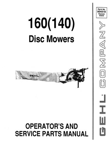
In general, any 45 hp (34 kw) 540 RPM tractor, which is equipped with a hydraulically-operated 3-point hitch and a single remote hydraulic output connection, can be used for operating the DM160 Disc Mower. The tractor 3-point linkage should have a freely adjustable top link and swivel cranks on the lower links. A tracking width of 59-1/2" (1510 mm) is recommended to allow sufficient space for the tractor wheels. Stabilizing bars or chains are essential. to help maintain the position of the tractor and Mower with respect to the standing crop.
1 - Stabilizer Bars or Chains
2 - Tractor Lower Link Swivel Crank
3 - Ground
4 - Track Width of 59-1/2" (1500 mm)
Fig. 5-1
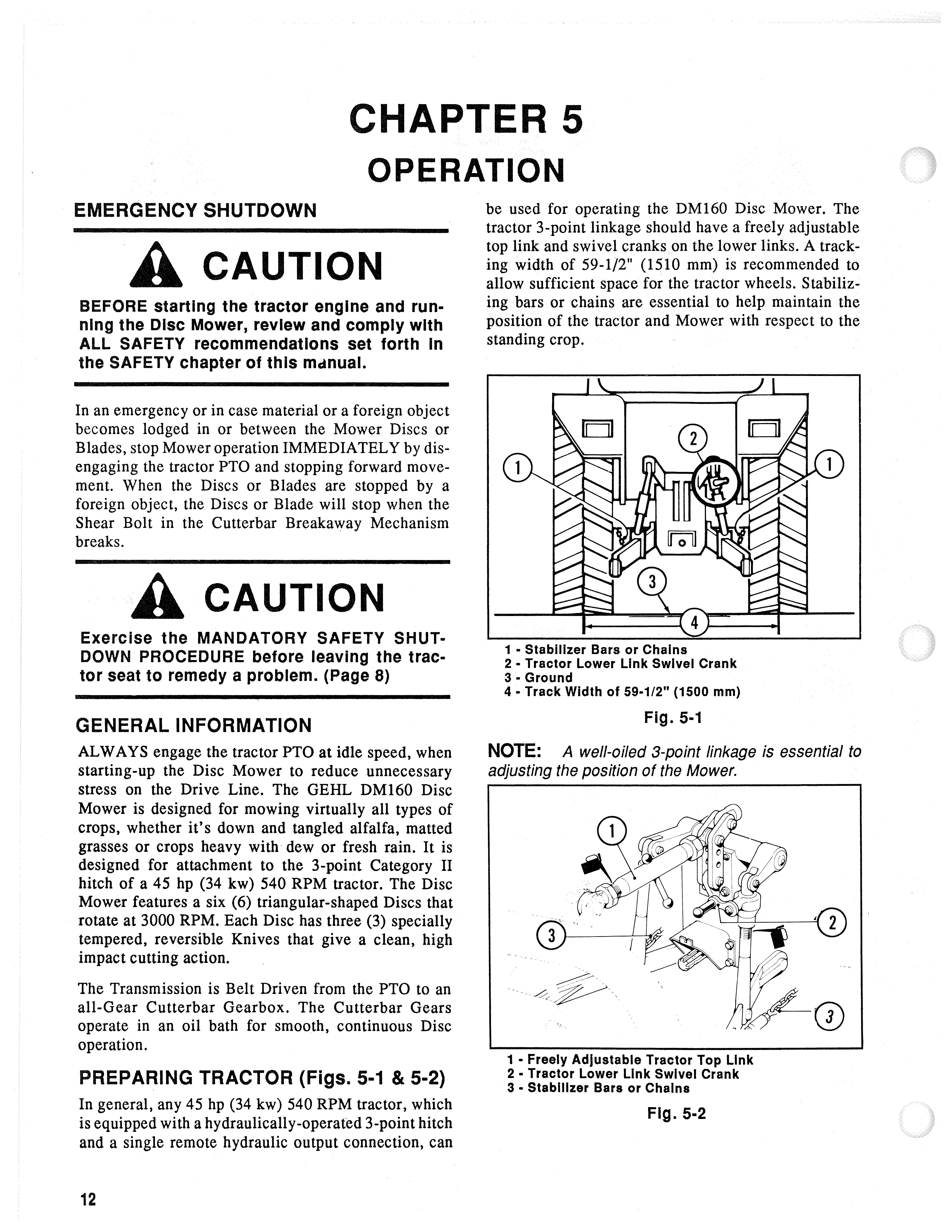
NOTE: A weI/-oiled 3-point linkage is essential to adjusting the position of the Mower.
1 - Freely Adjustable Tractor Top Link
2 - Tractor Lower Link Swivel Crank
3 - Stabilizer Bars or Chains
Fig. 5-2
MOUNTING TO TRACTOR (Figs. 5-3 through 5-8)
Back the tractor up to the Disc Mower with its linkage arms lined-up with the Mounting Pins on the Mower. Connect the Lower Link with crank handle last as this can be used to make up for height differences, if needed. Mount the top link, raise the Mower several inches (millimeters) and fix the Support Leg in its "transport" position. Check the position of the Mower to insure that the tractor lower links are horizontal. To detach the Disc Mower, reverse the preceding attachment procedure.
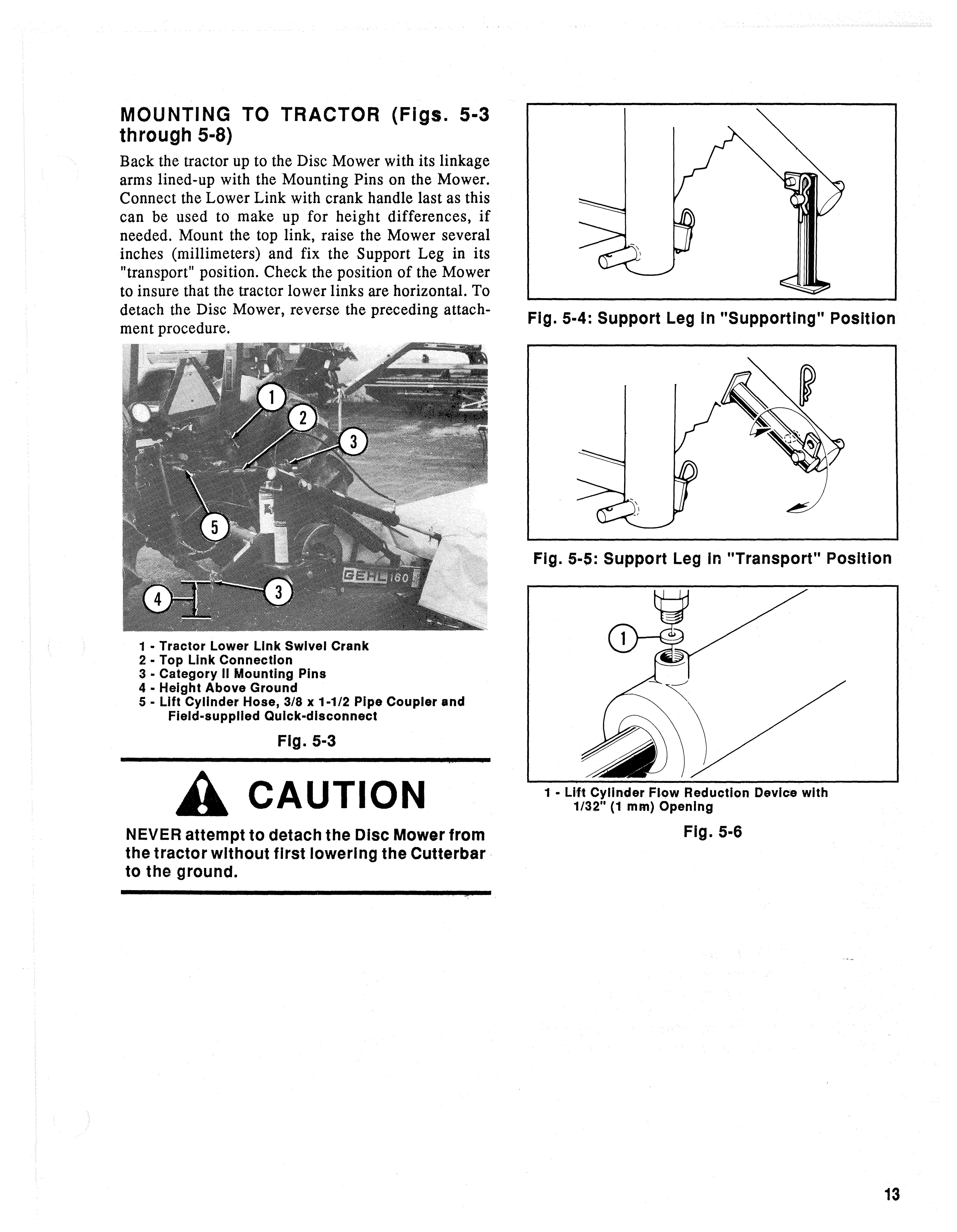
1 • Tractor Lower Link Swivel Crank
2 - Top Link Connection
3 • Category II Mounting Pins
4 - Height Above Ground
5 - Lift Cylinder Hose, 3/8 x 1-1/2 Pipe Coupler and Field-supplied Quick-disconnect
A Caution
NEVER attempt to detach the Disc Mower from the tractor without first lowering the Cutterbar to the ground.
1 • Alternate Hole In End of Link Tube
2 • Regular Mounting Hole In Link Tube
3 • Hole In Ram End of Hydraulic Cylinder
To use the hydraulic Lift Cylinder, a 3/8 x 1-1/2 Pipe Coupling and the appropriate quick-disconnect fitting (NOT provided) MUST be attached to the Lift Cylinder Hose. Use teflon tape (or equivalent pipe sealing compound) on all fitting connections to prevent leakage. The Lift Cylinder is furnished with a: flow reduction device to limit oil flow into the Cylinder. The opening in the flow reduction device is approximately 1/32" (1 mm); do NOT attempt to change the flow reduction.
NOTE: On some tractor models, when the normal hydraulic system is regulated by only the handle of the lower linkage, it is recommended to change the connection at the end of the hydraulic Cylinger Ram.
Move the Cutterbar to the horizontal position and set the arms ofthe tractor lower links 16 to 18" (400 to 450 mm) above the ground. Disconnect the MI0 x 45 Bolt which secures the Link Tube to the Ram. Then, reposition the Link Tube so that it can be secured to the Ram in the alternate hole. Then, replace and resecure the Bolt.
The tractor hydraulic control will now raise the Disc Mower first, and then the Cutterbar in a single operation. When using the hydraulic control, the lift control stop should be set so that the Cutterbar does NOT come above the horizontal when the Mower is raised. Refer to the "Mowing" topic in this chapter for additional details.
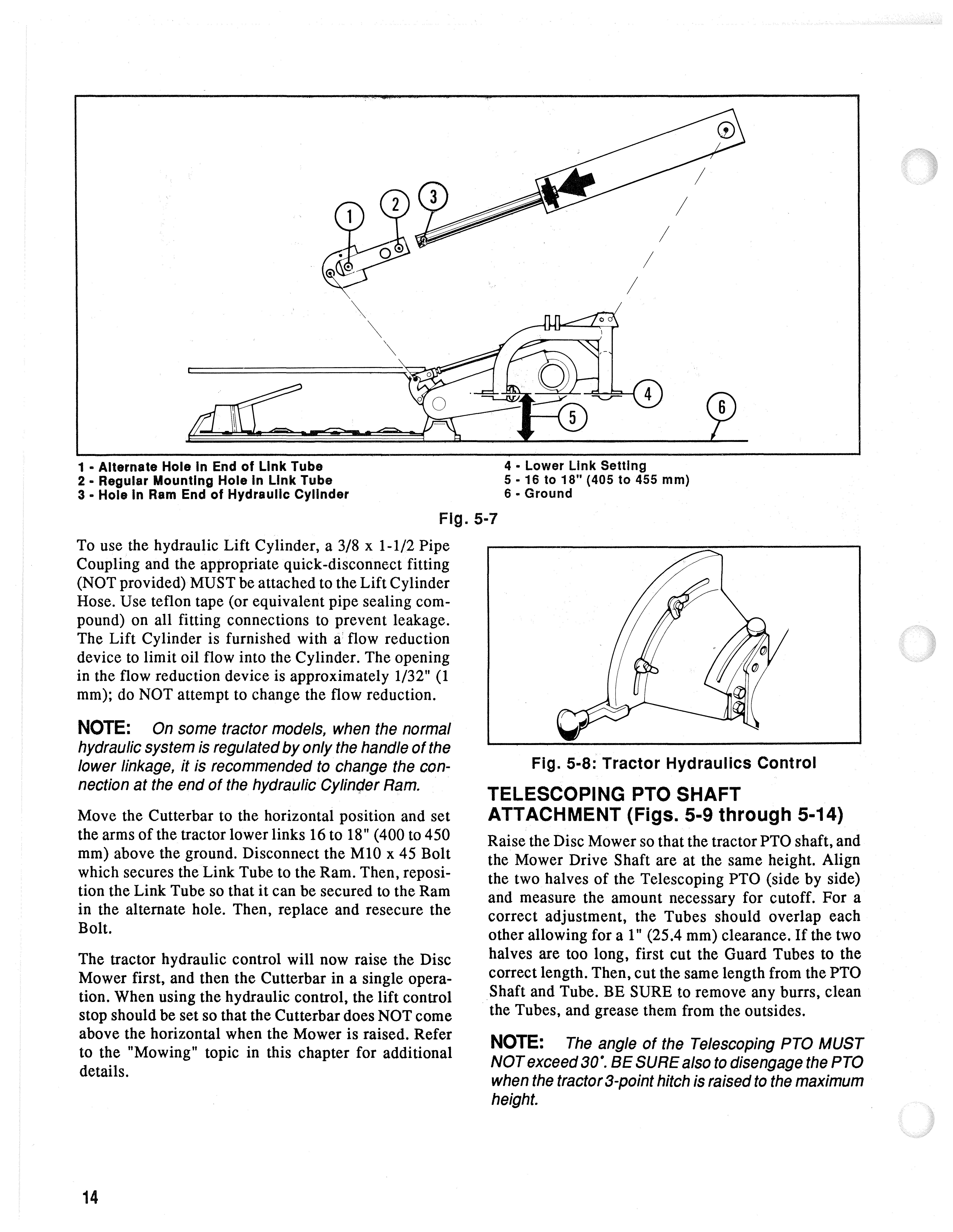
4 • Lower Link Setting
5·16 to 18" (405 to 455 mm)
6· Ground
Telescoping Pto Shaft
ATTACHMENT (Figs. 5-9 through 5-14)
Raise the Disc Mower so that the tractor PTO shaft, and the Mower Drive Shaft are at the same height. Align the two halves of the Telescoping PTO (side by side) and measure the amount necessary for cutoff. For a correct adjustment, the Tubes should overlap each other allowing for a 1" (25.4 mm) clearance. If the two halves are too long, first cut the Guard Tubes to the correct length. Then, cut the same length from the PTO Shaft and Tube. BE SURE to remove any burrs, clean the Tubes, and grease them from the outsides.
NOTE: The angle of the Telescoping PTO MUST NOT exceed 30'. BE SURE also to disengage the PTO when the tractor 3-point hitch is raised to the maximum height.
If the Telescoping PTO Drive is left too long or the Tubes are NOT greased regularly. the Mower Drive Bearings can become permanently damaged. NEVER use a hammer on the PTO ends and keep them well lubricated with grease. Attach the Guard Tube Chain securely to the tractor.
A Warning
BEFORE operating the Disc Mower, BE SURE that the PTO Guard Tube Is properly chained to the tractor PTO guard to prevent the Tube from turning.
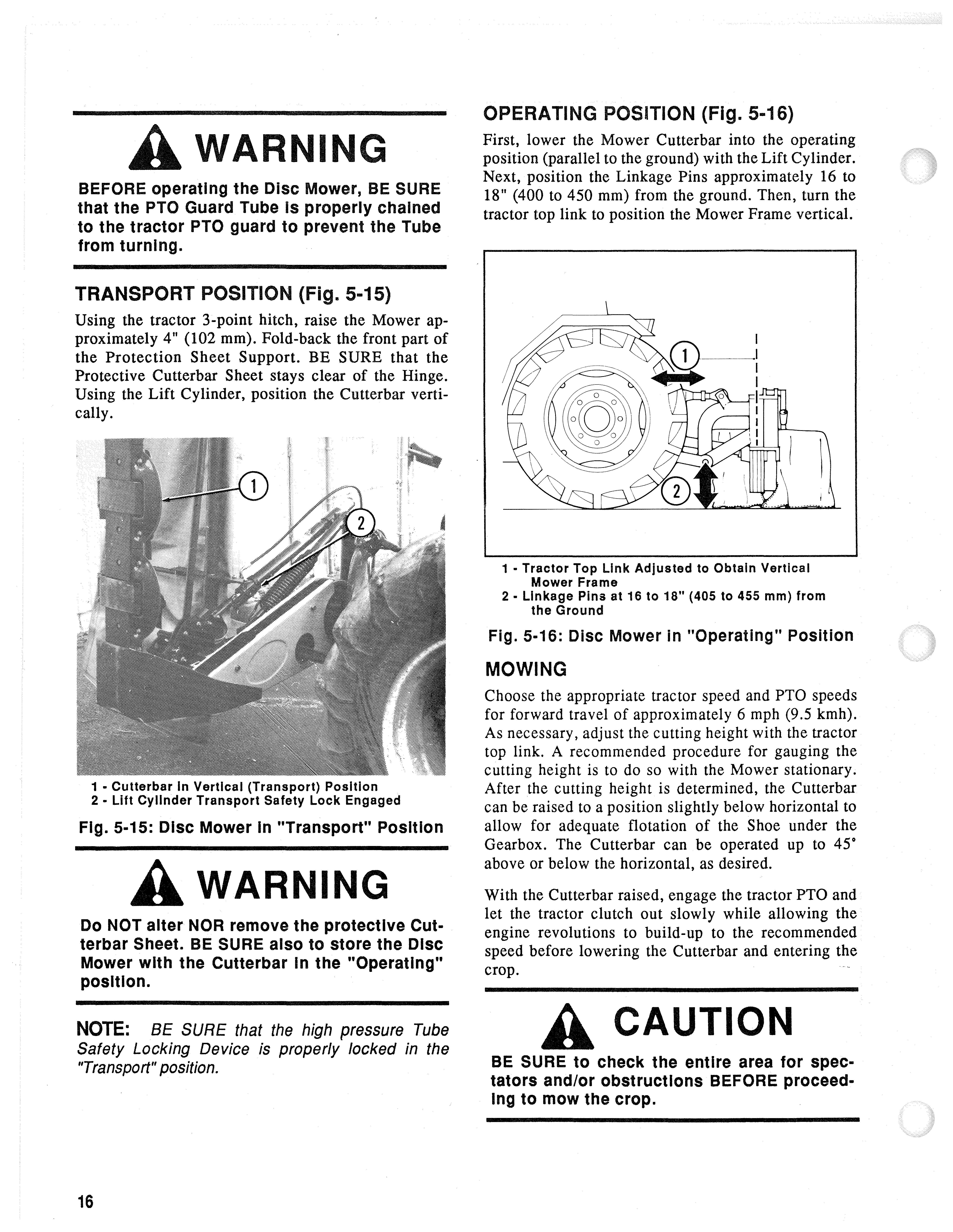
TRANSPORT POSITION (Fig. 5-15)
Using the tractor 3-point hitch, raise the Mower approximately 4" (102 mm). Fold-back the front part of the Protection Sheet Support. BE SURE that the Protective Cutterbar Sheet stays clear of the Hinge. Using the Lift Cylinder, position the Cutterbar vertically.
OPERATING POSITION (Fig. 5-16)
First, lower the Mower Cutterbar into the operating position (parallel to the ground) with the Lift Cylinder. Next, position the Linkage Pins approximately 16 to 18" (400 to 450 mm) from the ground. Then, turn the tractor top link to position the Mower Frame vertical.
1 • Cutterbar In Vertical (Transport) Position
2· Lift Cylinder Transport Safety Lock Engaged
Fig. 5-15: Disc Mower In "Transport" Position
Awarning
Do NOT alter NOR remove the protective Cutterbar Sheet. BE SURE also to store the Disc Mower with the Cutterbar In the "Operating" position.
NOTE: BE SURE that the high pressure Tube Safety Locking Device is properly locked in the "Transport" position.
1 • Tractor Top Link Adjusted to Obtain Vertical Mower Frame
2· Linkage Pins at 16 to 18" (405 to 455 mm) from the Ground
Fig. 5-16: Disc Mower In "Operating" POSition
Mowing
Choose the appropriate tractor speed and PTO speeds for forward travel of approximately 6 mph (9.5 kmh). As necessary, adjust the cutting height with the tractor top link. A recommended procedure for gauging the cutting height is to do so with the Mower stationary. After the cutting height is determined, the Cutterbar can be raised to a position slightly below horizontal to allow for adequate flotation of the Shoe under the Gearbox. The Cutterbar can be operated up to 45' above or below the horizontal, as desired.
With the Cutterbar raised, engage the tractor PTO and let the tractor clutch out slowly while allowing the engine revolutions to build-up to the recommended speed before lowering the Cutterbar and entering the crop.
A
Caution
BE SURE to check the entire area for spectators and/or obstructions BEFORE proceedIng to mow the crop.
SHOCK ABSORBER (Figs. 5-17 , 5-18 & 5-19)
The Disc Mower is provided with a Shock Absorber which MUST be fitted to the Cylinder end and to the Vertical Tube which is attached to the tractor 3-point hitch. Raise the Mower until the Inner Shoe is approximately 8" (205 mm) above the ground. Next, extend the Cylinder to lower the Cutterbar so that the Outside Shoe just touches the ground. Then, lower the tractor linkage to a distance of 16 to 18" (400 to 450 mm) between the linkage arms and the ground. At this position, Mounting Pin should be centered in Buffer Slot to provide for adequate Outside Shoe flotation.
Mowing Slopes
The Pin MUST be in the lowest position in the slot of the Link Tube. This can be achieved by keeping the hydraulic trailer connection lever pushed for a few seconds beyond the position where the Cutterbar is resting on the ground.
SWATHBOARD
The Outside Swathboard is attached to the end of the Cutterbar. The angle of the Swathboard can be changed by tightening or loosening the Nut. The Swathstick can be arranged in anyone of four positions or removed entirely, if desired. The actual position of the should always be adjusted according to the circumstances required, such as long, short or flattened crops.
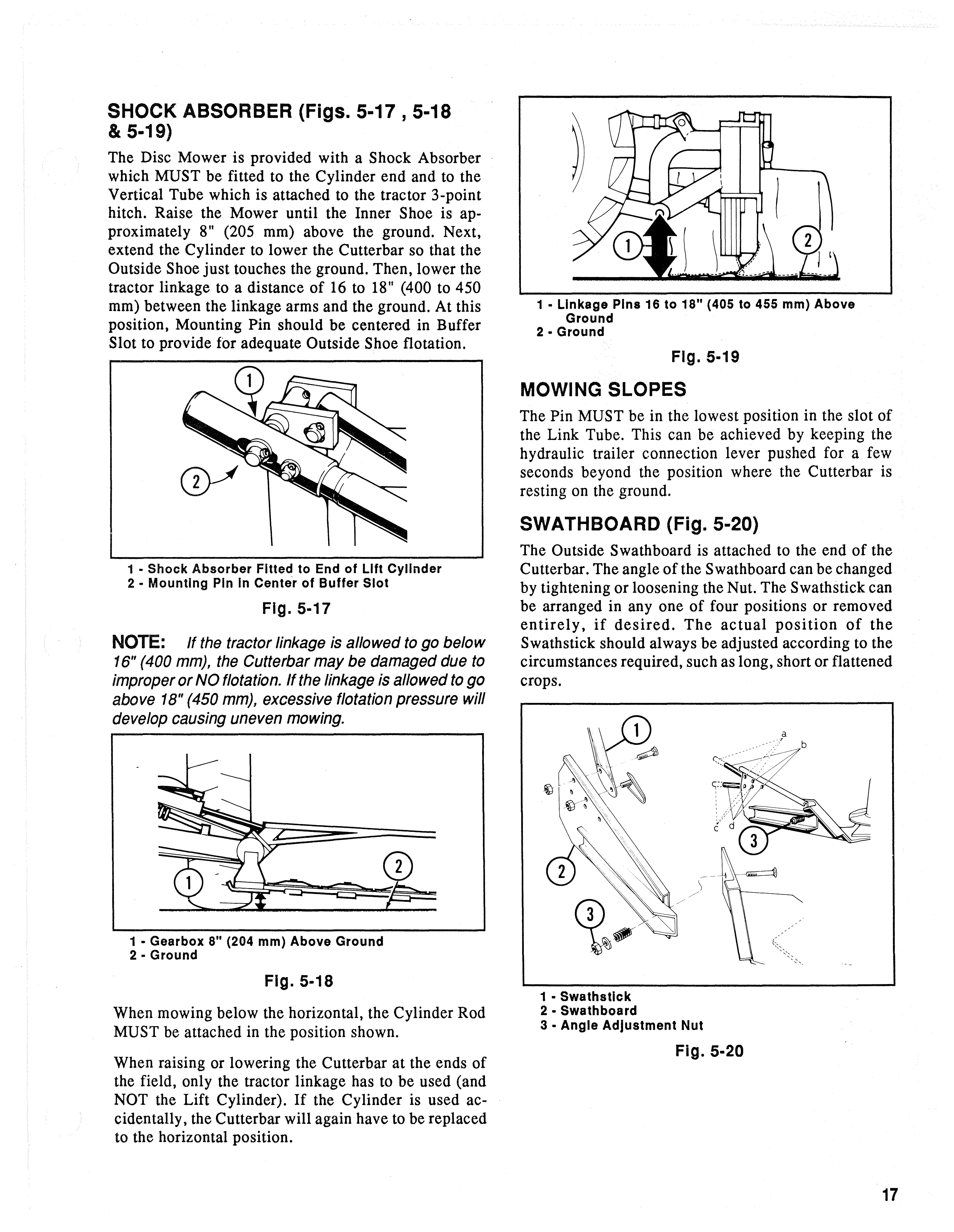
NOTE: If the tractor linkage is allowed to go be/ow 16" (400 mm), the Cutterbar may be damaged due to improper or NO flotation. If the linkage is allowed to go above 18" (450 mm), excessive flotation pressure will develop causing uneven mowing.
When mowing below the horizontal, the Cylinder Rod MUST be attached in the position shown.
When raising or lowering the Cutterbar at the ends of the field, only the tractor linkage has to be used (and NOT the Lift Cylinder). If the Cylinder is used accidentally, the Cutterbar will again have to be replaced to the horizontal position.
OVERLOAD PROTECTION (Figs. 5-21 & 5-22)
The Disc Mower Cutterbar is protected against obstacles by a single Cutterbar Breakaway Bolt. If the Bolt breaks, while operating the unit, attempt to determine the cause of the Bolt failure before replacing it and attempting to re-secure operation. The Bolt is equipped with two Nuts. To properly install the Bolt, first attach the one Nut, using finger-tight pressure. Then, install and tighten the second Nut using a wrench.