11 minute read
Fuel/Lubrication/Cooling

! WARNING
Whenever the gasline hoses are removed (other than for pressure testing), the battery must be disconnected to prevent inadvertent activation of the electric fuel pump. ! WARNING
Whenever any maintenance or inspection is performed on the fuel system during which there may be fuel leakage, there should be no welding, smoking, open flames, etc., in the area.
SPECIAL TOOLS A number of special tools must be available to the technician when performing service procedures in this section. Refer to the current Special Tools Catalog for the appropriate tool description. NOTE: When indicated for use, each special tool
will be identified by its specific name, as shown in the chart below, and capitalized.
NOTE: Special tools are available from the Service
Department.
Description p/n
Oil Pressure Test Kit 0644-495
TROUBLESHOOTING
1.Verify that the electric fuel pump is operating by listening for a “whirring” sound for several seconds after the ignition switch is turned to the ON position.
If no sound can be heard, see EFI
Sensors/Components in Electrical System. 2.Check for a diagnostic trouble code (DTC) on the
LCD gauge. If a code is flashing, see Diagnostic
Trouble Codes (DTC) in Electrical System. 3.Make sure there is sufficient, clean gas in the gas tank.
Gas Tank
! WARNING
Whenever any maintenance or inspection is made on the fuel system during which there may be fuel leakage, there should be no welding, smoking, open flames, etc., in the area.
REMOVING
1.Remove the passenger seat, and battery access panel.
Disconnect battery cables from battery. 2.Disconnect the fuel filler hose from the fender. Seal off the hose to prevent objects from entering the hose.
XX084
3.Disconnect the gas tank vent hose
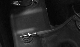
XX105
! WARNING
Extreme care must be taken when removing gas line. Pressure in the line may cause gas to spray out.
4.Disconnect wire harness connector for fuel pump.
Disconnect the gas line by pushing in on tabs.
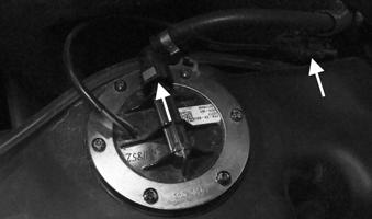
XX106
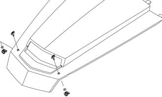
5.Remove the cap screws securing brackets for gas tank. Remove the three brackets holding tank down.
Slide gas tank toward front of vehicle
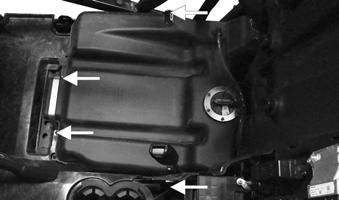
XX104
6.Remove gas tank.
INSTALLING
1.Place the gas tank into position; then connect the gas line hose, vent hose, and fuel pump. 2.Place the three brackets into place. 3.Install and tighten cap screws securing brackets securing the gas tank. 4.Place the battery into position and connect the battery cables (positive cable first). Tighten the cables securely. 5.Install the battery access panel and passenger seat.
Oil Pump
NOTE: Whenever internal engine components wear
excessively or break and whenever oil is contaminated, the oil pump should be replaced.
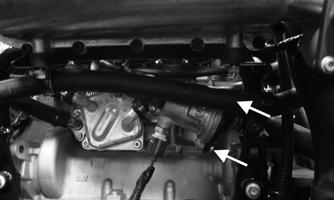
TESTING OIL PUMP PRESSURE
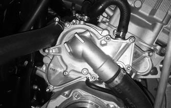
1.Remove the cargo box. 2.Remove the cap screw and washer located on the upper portion of the engine near the #3 cylinder intake (A).
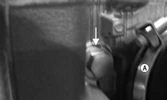
XX459
NOTE: The cap screw is M8 (diameter) x 1.25
(thread pitch) x 12 mm (length), and the crush washer is approximately 1.15 mm thick.
3.Install the Oil Pressure Test Kit with a suitable fitting; then start the engine. While the engine is running, there should be no leaks. 4.With a radiator fan on, increase the engine speed to 4800-4900 RPM. The oil pressure should be approximately 28-35 psi. 5.Remove the Oil Pressure Test Kit and suitable fitting from the engine and install cap screw with a new crush washer. Securely tighten the cap screw with washer.
6.Install the cargo box. NOTE: If oil pressure is lower than specified, check
for an oil leak, clogged oil filter, or defective oil pump.
NOTE: If oil pressure is higher than specified, check
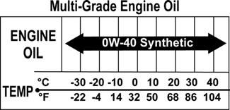
for too heavy engine oil weight (see General Information/Foreword), clogged oil passage, or improper installation or type of oil filter.
Fuel Pump
NOTE: The fuel pump is not a serviceable
component and must be replaced as an assembly (see FUEL PUMP/FUEL LEVEL SENSOR in the Electrical System section).
Fuel/Vent Hoses
Inspect the fuel lines per the maintenance schedule. Damage from aging may not always be visible. Do not bend or obstruct the routing of the vent hose or fuel return hose.
Liquid Cooling System
NOTE: Use a good quality, biodegradable
glycol-based, automotive-type antifreeze. When filling the cooling system, use the recommended coolant/water mixture or one which will satisfy the coldest anticipated weather conditions of the area in accordance with the coolant manufacturer’s recommendations.
! WARNING
Never check the coolant level when the engine is hot or the cooling system is under pressure.
CAUTION
After operating the vehicle for the initial 5-10 minutes, stop the engine, allow the engine to cool down, and check the coolant level. Add coolant as necessary.
NOTE: Debris in the engine compartment or packed between the cooling fins of the radiator can reduce cooling capacity. Using a garden hose, wash the radiator to remove any debris preventing air flow.
CAUTION
Do not use a pressure washer to clean the radiator core. The pressure may bend or flatten the fins causing restricted air flow, and electrical components on the radiator could be damaged. Use only a garden hose with spray nozzle at normal tap pressure.
Always maintain the coolant level at the cold full line of the coolant reservoir.
Checking Coolant 1.Remove the hood; then inspect the coolant level cold. The level shouldn’t be lower than the cold full line. When it’s at operating temperature, the coolant level may be above the cold full line.
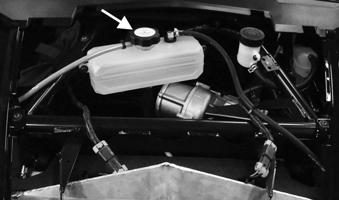
XX115
Bleeding Cooling System While the cooling system is being filled, air pockets may develop; therefore, make sure the cooling system is properly bled, with no trapped air in the system. 1.Open the coolant bleeder valve and fill the coolant reservoir to the full mark; then let it sit with the bleeder valve open for at least 15 minutes.
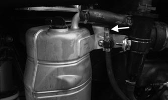
XX455
2.Close the bleeder valve; then start the engine; then check for any leaks and monitor the temperature of the vehicle via the diagnostic menu. Run the vehicle until the radiator fan cycles on and then off. 3.Turn the engine off and wait until engine is cool.
Add the recommended coolant/water mixture to fill the coolant reservoir.
Radiator
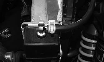
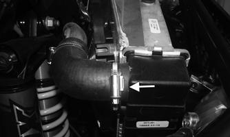
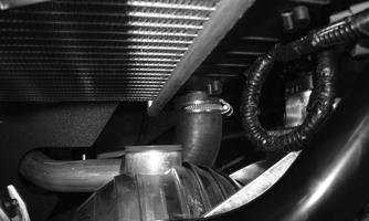
REMOVING 1.Remove the hood, and front fenders. 2.Using a suitable clamp, clamp the coolant hoses off in the areas indicated.
XX450
XX451
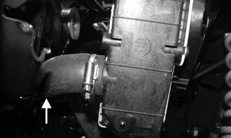
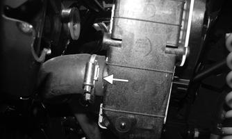
3.Using a suitable container to catch the coolant, loosen the drain at the bottom of the radiator on the passenger side.
XX452
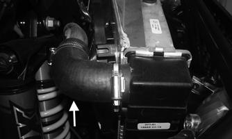
4.Remove the upper hose on the driver’s side; then remove the two remaining hoses.
XX453
XX450A
XX452
5.Disconnect the cooling fan electrical connectors and note the location of any straps securing the electrical connectors.

XX447
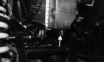
6.Remove the two cap screws securing the upper radiator bracket to the frame; then remove the upper radiator bracket; then remove the inner headlights from the headlight housings on both sides.
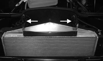
XX447A
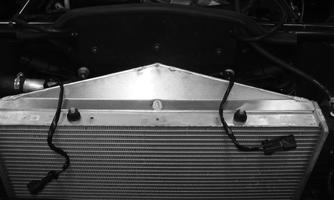
XX448
XX449
7.Remove the radiator/fan assembly from the vehicle by lifting vertically. NOTE: If the radiator is to be replaced, transfer the
cooling fans, coolant hoses, coil, and attaching hardware to the replacement radiator.
INSTALLING 1.Place the assembled radiator/fan assembly into position; then close the drain at the bottom of the radiator.
2.Connect the coolant hoses to the radiator; then tighten clamps securing hoses to radiator. 3.Position the upper radiator bracket to the frame; then install the two cap screws securing the radiator bracket to the frame.
XX447A
4.Install the inner headlights to the headlight housing on both sides; then connect the electrical connectors for the cooling fans; then secure back in place as noted during the removal procedure.
XX447
5.Remove the suitable clamps on the hoses; then install the fenders.
6.Pour the proper mixture and quantity of coolant into the coolant tank.
7.Bleed the cooling system. 8.Install the hood.
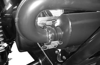
Thermostat
REMOVING NOTE: The thermostat is located in an in-line
housing in a coolant hose in front of the engine.
1.Remove the rear splash panel that is behind the seats. 2.Remove the two cap screws securing the thermostat housing together. Remove the thermostat.
XX454
INSPECTING 1.Inspect the thermostat for corrosion or spring damage. 2.Using the following procedure, inspect the thermostat for proper operation:
A.Suspend the thermostat in a container filled with water.
B.Heat the water and monitor the temperature with a thermometer.
C.The thermostat should start to open at 83.0-87.0° C (181-189° F).
D.If the thermostat does not open, it must be replaced. 3.Inspect all coolant hoses, connections, and clamps for deterioration, cracks, and wear. NOTE: All coolant hoses and clamps should be
replaced every four years or 4000 miles.
INSTALLING 1.Place the thermostat into the thermostat housing; then secure the thermostat housing together with the two cap screws. 2.Fill the cooling system with the recommended antifreeze. Check for leakage. 3.Install the rear splash panel; then bleed the cooling system.
Fans
REMOVING 1.Remove the radiator.
2.Remove the fan assembly from the radiator.
INSTALLING 1.Position the fan assembly on the radiator; then secure with existing hardware. 2.Install the radiator.
Water Pump
! WARNING
When servicing the water pump, disconnect the battery cables to avoid injury.
REMOVING 1.Drain the engine coolant. 2.Remove the outer CVT cover, the driven clutch, drive clutch and the belt.
3.Remove the inner CVT cover to gain access to the water pump assembly.
XX446
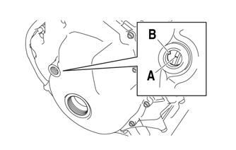
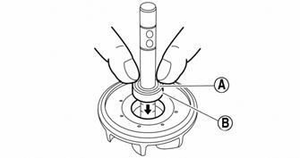
4.Obtain top-dead-center (TDC) by rotating the crankshaft (clockwise) until the mark (A) on the magneto rotor is aligned with the pointer (B) on the magneto cover and the #3 piston is at TDC. NOTE: There are two “I” marks on the magneto
rotor. If the “I” mark (with the “H” mark) is shown, turn the crankshaft 180° until the “I” mark (without the “H” mark) is shown.
SNO-278
DISASSEMBLING/ASSEMBLING
SNO-372
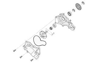
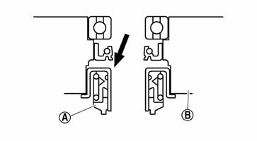
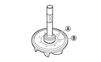
1.Remove the screws securing the water pump cover to the water pump; then remove the impeller. 2.Remove the water pump seal (A) from the water pump housing (B).
SNO-373A
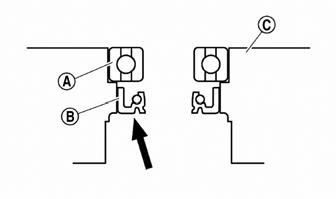
3.Remove the bearing (A) and the oil seal (B) from the water pump housing (C).
SNO-863
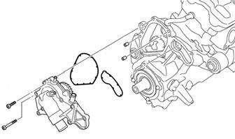
5. Disconnect all hoses from the water pump; then remove the Allen-head screws securing the water pump assembly to the crankcase; then remove the assembly. Account for two dowel pins and two gaskets.
SNO-374A
4.Remove the rubber damper holder (A) and the rubber damper (B) from the impeller using a small flat-head screwdriver making sure not to damage the impeller shaft.
SNO-375A
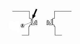
INSTALLING 1.Apply tap water or coolant to the outer surface of the new oil seal; then install the oil seal (A) into the water pump housing using a socket of the same diameter.
SNO-378A
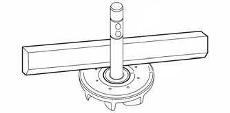
4.Using a straight edge, make sure the impeller is flush with the damper.
SNO-379
5.Install the impeller assembly into the housing and secure using the existing circlip. 6.Obtain top-dead-center (TDC) by rotating the crankshaft (clockwise) until the mark (A) on the magneto rotor is aligned with the pointer (B) on the magneto cover and the #3 piston is at TDC. NOTE: There are two “I” marks on the magneto
rotor. If the “I” mark (with the “H” mark) is shown, turn the crankshaft 180° until the “I” mark (without the “H” mark) is shown.
SNO-376A
2.Install the bearing using a socket of the same diameter; then apply sealant to the water pump housing; then install the water pump seal using an appropriate seal installation tool.
3.Apply tap water or coolant to the impeller shaft; then press the rubber damper holder (A) and rubber damper (B) onto the impeller shaft.
CAUTION
Never apply oil or grease onto the water pump seal surface.
SNO-863
7.Install the water pump and secure using the existing screws. Tighten to 8.7 ft-lb. 8.Install the inner CVT cover, drive clutch, driven clutch, and the drive belt. Install the outer CVT cover.
9.Fill the cooling system.
Troubleshooting
Problem: Starting impaired Condition Remedy
1. Gas contaminated 1.Drain gas tank and fill with clean gas
Problem: Idling or low speed impaired Condition Remedy
1. Gas contaminated 1.Drain gas tank and fill with clean gas 2. Throttle body dirty 2.Clean throttle body
Problem: Medium or high speed impaired Condition Remedy
1. High RPM “cut out” against RPM limiter 1.Decrease RPM speed