15 minute read
Steering/Body/Controls

The following steering components should be inspected periodically to ensure safe and proper operation: A.Steering wheel secure. B.Steering has equal and complete full-left and full-right turning capability. C.Steering sector mounting bolts tight. D.Ball joints not worn, cracked, or damaged. E.Tie rods not bent or cracked.
F.Knuckles not worn, cracked, or damaged. G.Cotter pins not damaged or missing. H.Steering wheel tilt locks securely. The frame and welds should be checked periodically for damage, bends, cracks, deterioration, broken components, and missing components.
Hood/Rear Cargo Tray/Grille
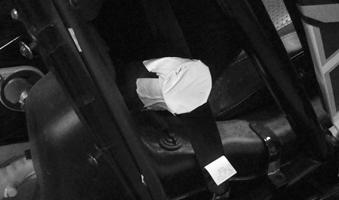
REMOVING/INSTALLING HOOD
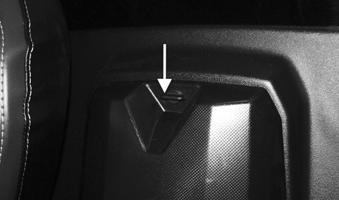
1.Turn the two 1/4-turn fasteners counterclockwise and remove hood.
VOR-471
2.Insert the tabs on the rear of hood into the rear portion of the front body panels. Lay the hood down flat.
Turn both of the fasteners clockwise securing the hood.
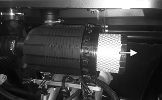
REMOVING/INSTALLING REAR CARGO TRAY
1.Remove fasteners from the rear cargo tray by turning counterclockwise
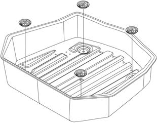
VOR-474
2.Remove rear cargo tray by lifting vertically. 3.Rear cargo tray is directional. Install the rear cargo tray. 4.Secure with fasteners by turning clockwise. Tighten fasteners securely
REMOVING GRILLE
1.Remove hood.
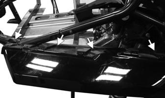
2.Remove fasteners securing lower fascia. Remove lower fascia.

VOR-472
3.Remove the fasteners securing the grille.
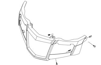
VOR-473
4.Remove grille by slightly lifting fenders while carefully sliding grille downward.
CLEANING AND INSPECTING GRILLE Clean any dirt or debris from the grille webbing. This helps air flow to the radiator.
INSTALLING GRILLE Place the grille into position and secure it using the existing cap screws. Tighten all hardware to 60 in.-lb.
Body Panels
REMOVING REAR FASCIA
1.Remove the rear cargo tray. 2.Remove the wire harness connected to the taillights.
Taillight removal is not required to remove rear fascia.
3.Remove the cap screws securing the rear fascia.
Remove rear fascia.
! WARNING
The heat deflectors under the rear cargo tray have sharp edges and can cause serious injury if care is not taken.
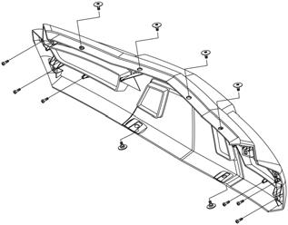
VOR-475
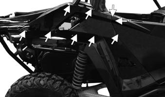
REMOVING REAR FENDERS
1.Remove rear cargo tray. 2.Remove rear fascia.
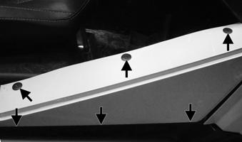
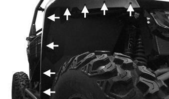
3.Remove cap screws securing rear upper front fender.
Remove rear upper front fender.
XX085D
XX088

XX087
XX086
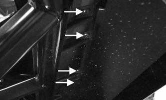
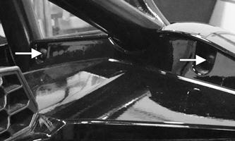
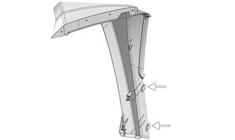
4.Remove the cap screws securing the rear upper fender. Remove rear upper fender.
XX085A1
XX089
XX090
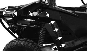
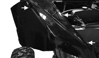
5.Remove the cap screws securing the rear lower fender. When removing right side proceed to step 6. When removing left side, remove rear lower fender.
XX085B1 XX091
XX092
XX093
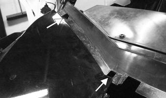
6.When removing right rear fenders, loosen the gas tank filler hose clamp behind the passenger seat.
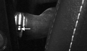
XX083
7.Remove the panel from the frame while also pulling on the filler hose. Seal off the hose to prevent objects from entering the hose.


XX084
INSTALLING REAR FENDERS
1.When installing right rear fender, install filler hose onto fender. Tighten hose clamp on gas tank filler hose.
XX083
2.Install the rear lower fender. Secure with cap screws.
XX085B1 XX091
XX092
3.Install the rear upper fender. Secure with cap screws.
XX085A1
XX089

XX090
4.Install the rear upper front fender. Secure with cap screws.
XX085D

XX088
XX087 XX086

REMOVING SIDE PANELS To remove a side panel, remove the cap screws and push pins securing the side panel to the frame; then remove the panel. Front and/or rear fender removal will make side panel removal easier.
XX098
INSTALLING SIDE PANELS Front and/or rear fender removal will make side panel installation easier. Install the cap screws and push pins securing the side panel to the frame.
XX098
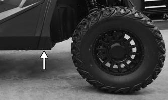
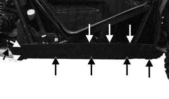
REMOVING/INSTALLING ROCKER PANELS
1.Remove push pins and cap screws securing the rocker panel to the frame. Remove rocker panel downward.
XX107
2.Install rocker panel upward toward vehicle body.
Install push pins and cap screws securing the rocker panel to frame.
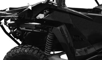
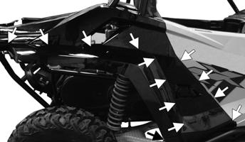
REMOVING FRONT FENDERS
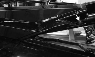
1. Remove fender flare fasteners. Remove fender flare being careful of the tabs at the rear of fender.
XX099
XX476
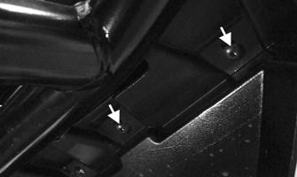
2.Remove hood. (see Removing/Installing Hood in this section). 3.Remove fender fasteners. Lift slightly on the front and pull toward front of vehicle.
XX100
INSTALLING FRONT FENDERS
1.Align tabs on rear portion of fender into slots.
XX101
2.Install fender fasteners securing fender.
XX100
3.Place fender flare into position being careful of the tabs at the rear of fender; then install fender flare fasteners securing fender flare.
XX476
XX099
4.Install hood (see Removing/Installing Hood in this section).
Front Wheel Alignment
NOTE: All measurements and adjustments must be
made with the vehicle unloaded.
NOTE: Make sure the paint alignment marks on the
steering rack are aligned.

PK118A
Mark the centerline of the front tires at the front and rear of the tire; then using a tape measure, measure and record the distance between the marks at the front and rear. The front measurement should be 3-6 mm (1/8-1/4 in.) greater than the rear measurement (toe-out).

XX463C
To adjust the wheel alignment, use the following procedure: NOTE: The tie rod threads are reverse thread.
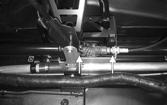
1.Center the steering rack; then using an open-end wrench to hold the tie rod (A), loosen the outer jam nuts (B).
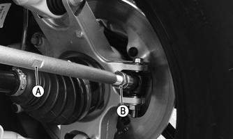
XX473
CAUTION
Always use a wrench to hold the tie rod ends when loosening or tightening the jam nuts or damage to the boots could occur.
2.Turn the left-side and right-side tie rods in equal increments to achieve the proper toe-out; then tighten the jam nuts (B) securely.
Shift Lever
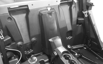
REMOVING
1.Remove both seats; then remove the 1/4-turn fastener securing the rear cover console. Remove the cover.

XX235
2.Remove the screws securing the center console and the handle; then remove the shift knob. Remove the console, handle, and knob.
XX233
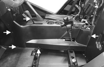
XX234
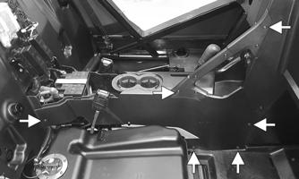
3.Remove the screw and nut securing the shift lever to the shift cable; then remove the shoulder screw and nut securing the lever to the frame and the bracket.
Remove the shift lever. Account for two bushings.
XX236
INSTALLING
1.Install both bushings into the shift lever; then secure the shift lever to the frame and the bracket using the existing shoulder screw and new nut. Tighten to 8 ft-lb (11 N-m). 2.Secure the shift cable to the bottom of the shift lever using the existing screw and new nut. Tighten to 8 ft-lb (11 N-m). 3.Install the center console, handle, shift knob, rear console, and both seats.
Shift Cable
REMOVING
1.Remove both seats, rear console cover, handle, and the center console.
2.Remove the E-clip securing the shift cable to the transaxle.

XX237
3.While holding the nut (B), loosen the jam nut (A) and remove the shift cable from the transaxle.
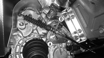
XX238 XX240
4.Remove the cap screw and lock nut securing the shift cable to the shift lever. Loosen the jam nut securing the shift cable to the shift bracket. Remove the shift cable. 2.Once the proper adjustment is achieved, tighten the jam nut to 20 ft-lb (27 N-m). NOTE: After the jam nuts are secure, check the
shift cable again for proper adjustment.
XX239
INSTALLING
1.Install the new shift cable in place noting the routing from removing. Secure to the transaxle with the
E-clip and jam nut. Finger-tighten the jam nut at this point. 2.Install the shift cable end to the shifter bracket and secure with the cap screw, new lock nut, and jam nut. 3.Adjust the shift cable (see ADJUSTING in this sub-section). After cable is properly adjusted, tighten the jam nuts to 20 ft-lb (27 N-m). 4.Install the center console, handle, rear console cover, and both seats.
ADJUSTING
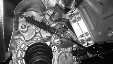
1.With the transmission in neutral, loosen the jam nut (A) and adjust the cable until there is a small amount of free-play in the shift lever moving forward and backward while still in neutral.
LCD Gauge
REMOVING
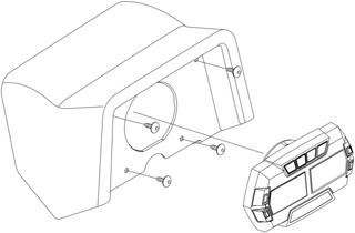
1.Remove the four screws securing the gauge pod to the steering bracket; then disconnect the gauge from the harness. Remove the gauge pod assembly.
VOR-500
INSTALLING
1.Press the gauge into the gauge pod; then connect the harness to the back of the gauge. 2.Secure the gauge pod assembly to the steering bracket using the four screws. Tighten securely.
Exhaust System
REMOVING
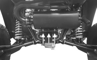
1.Remove the rear cargo tray. Remove the three screws securing the rear of the cargo tray heat shield to the rear fascia heat shield.
VOR-502
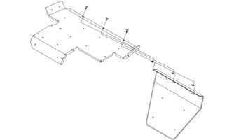
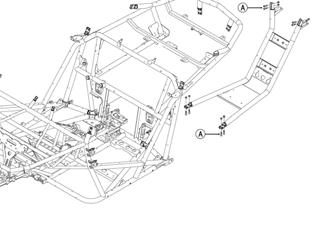
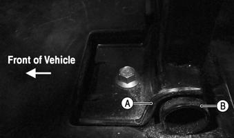
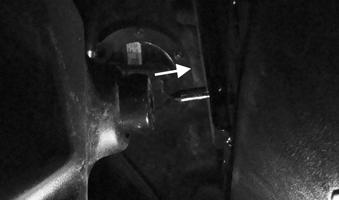
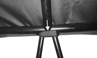
2.Remove the screws (A) securing the skid plate; then remove the skid plate. Remove the screws (B) and nuts securing the rear hoop frame to the main frame.
Remove the hoop frame assembly.

VOR-501
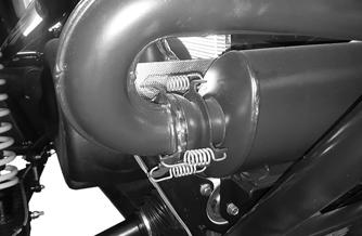
3.Remove the springs securing the muffler to the manifold.
XX242

4.Remove the three cap screws and nuts securing the muffler to the rear transaxle mount; then slide the muffler to the right and out from the vehicle.
XX259
5.Remove all screws securing the rear cargo tray exhaust heat shield to the frame; then remove the heat shield assembly rearward and out of the vehicle.
XX261
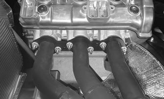
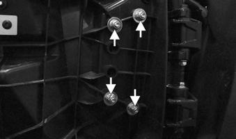
6.Remove the six nuts attaching the exhaust header to engine; then disconnect the oxygen sensor from the main harness.
XX260
7.Pull the exhaust header straight back until exhaust header is free from exhaust stud bolts on engine.
Remove manifold from vehicle. Account for three gaskets.
INSTALLING The manufacturer recommends the use of new
exhaust gaskets.
1.Align the manifold with the engine stud bolts. Push exhaust header into place so the engine exhaust studs go through the exhaust header. 2.Starting in the middle, secure using the existing nuts.
Tighten to 16 ft-lb (22 N-m).
XX260
3.Connect the oxygen sensor to the main harness; then secure the sensor wires using two push-mount cable ties.
4.Install the rear cargo tray heat shield assembly to the frame using the existing screws. Tighten securely. 5.Position the muffler with the manifold and secure using the existing springs; then secure the muffler to the transaxle bracket using the existing cap screws, washers, and nuts. Tighten to 16 ft-lb (22 N-m).
XX259
6.Install the rear hoop frame and secure using the existing screws and new nuts. Tighten to 35 ft-lb (48 N-m). 7.Install the skid plate and the rear cargo tray.
Seats
REMOVING/INSTALLING DRIVER’S SEAT
1.To remove seat, pull the seat lock lever up. Raise the rear of the seat and tilt the seat forward.
XX066
2.To install seat, slide the front of the seat frame (B) into the seat retainers (A) and push down firmly on the rear of seat. The seat should automatically lock into position.
XX067
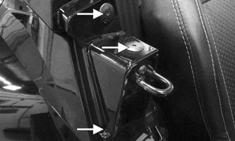
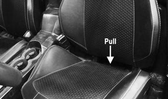
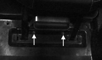
REMOVING/INSTALLING PASSENGER SEAT
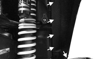
1.To remove seat, remove two screws located near the floor of the front of the passenger-side seat frame.
XX102
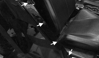
2.Pull toward the front of the vehicle on the seat back.
Pulling the seat frame clear of the pins that are on the backside of the seat frame.
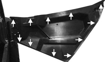
XX103
3.To install seat, align the front of the seat frame to the approximate mounting location in front of gas tank and align the pins on the rear of the seat assembly with the eyelet. Push to the rear of the vehicle on the seat frame seating the pins into the eyelets.

XX103A
4.Install the two screws located near the floor in front of the seat frame.
XX102
Doors
REMOVING Inspect the doors for broken or bent tubes, hinges, or latches. Make sure the latches engage and lock securely. 1. Remove cap screws securing the outer door skin.
XX096
2.Remove the fasteners securing the door to hinge.
XX097
INSTALLING
1.Install the cap screws from the interior side of the door; tighten cap screws securing the door to hinge.
XX097
2.Attach outer door skin to door. Install and tighten cap screws securing outer door skin to door.
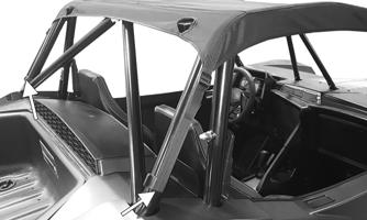
Deluxe Bimini Top
REMOVING/INSTALLING 1.Loosen all four straps at each corner of the ROPS; then disconnect all four straps from the clamps at each corner of the ROPS.

XX477A
XX478
2.Unfasten the strap on the front portion of the ROPS; then remove the Deluxe Bimini Top.
XX479
3.Position the Deluxe Bimini Top into position and connect all four straps to the clamps at each corner of the ROPS; then tighten all four straps at each corner of the ROPS.
4.Fasten the strap on the front portion of the ROPS.
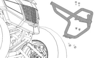
Front Bumper
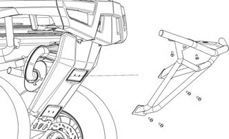
REMOVING/INSTALLING 1.Remove the four cap screws and two lock nuts securing the front bumper. Remove the front bumper.
VOR-380
2.Position the bumper into place; then install the four cap screws and two lock nuts.
Rear Bumper
REMOVING/INSTALLING 1.Remove the six cap screws securing the rear bumper.
Remove the rear bumper.
VOR-402
2.Position the bumper into place; then install the six cap screws.
Troubleshooting
Problem: Handling too heavy or stiff Condition Remedy
1. Front wheel alignment incorrect 1.Adjust alignment 2. Lubrication inadequate 2.Lubricate appropriate components 3. Tire inflation pressure incorrect 3.Adjust pressure 4. Tie rod ends seizing 4.Replace tie rod ends 5. Linkage connections seizing 5.Repair — replace connections 6. EPS malfunction 6.Troubleshoot — replace EPS
Problem: Steering oscillation Condition Remedy
1. Tires inflated unequally 1.Adjust pressure 2. Wheel(s) wobbly 2.Replace wheel(s) 3. Wheel hub cap screw(s) loose — missing 3.Tighten — replace cap screws 4. Wheel hub bearing worn — damaged 4.Replace bearing 5. Tie rod ends worn — loose 5.Replace — tighten tie rod ends 6. Tires defective — incorrect 6.Replace tires 7. A-arm bushings damaged 7.Replace bushings 8. Bolts — nuts (frame) loose 8.Tighten bolts - nuts
Problem: Steering pulling to one side Condition Remedy
1. Tires inflated unequally 1.Adjust pressure 2. Front wheel alignment incorrect 2.Adjust alignment 3. Wheel hub bearings worn — broken 3.Replace bearings 4. Frame distorted 4.Repair — replace frame 5. Shock absorber defective 5.Replace shock absorber
Problem: Steering impaired Condition Remedy
1. Tire pressure too high 1.Adjust pressure 2. Steering linkage connections worn 2.Replace connections 3. Cap screws (suspension system) loose 3.Tighten cap screws
Problem: Tire wear rapid or uneven Condition Remedy
1. Wheel hub bearings worn — loose 1.Replace bearings 2. Front wheel alignment incorrect 2.Adjust alignment
Problem: Steering noise Condition Remedy
1. Caps screws — nuts loose 1.Tighten cap screws — nuts 2. Wheel hub bearings broken — damaged 2.Replace bearings 3. Lubrication inadequate 3.Lubricate appropriate components
Problem: Rear wheel oscillation Condition Remedy
1. Rear wheel hub bearings worn — loose 1.Replace bearings 2. Tires defective — incorrect 2.Replace tires 3. Wheel rim distorted 3.Replace wheel 4. Wheel hub cap screws loose 4.Tighten cap screws 5. Trailing arm bushings worn 5.Replace bushings or link