16 minute read
Suspension

The following suspension system components should be inspected periodically to ensure proper operation. A.Shock absorber rods bent, pitted, or damaged. B.Reservoirs damp or leaking. C.Shock absorber body damaged, punctured, or leaking. D.Shock absorber eyelets broken, bent, or cracked. E.Shock absorber eyelet bushings worn, deteriorated, cracked, or missing.
F.Shock absorber spring broken or sagging. G.Sway bar mountings tight and bushings secure. H.Proper pre-load and damping for conditions.
SPECIAL TOOLS A number of special tools must be available to the technician when performing service procedures in this section. Refer to the current Special Tools Catalog for the appropriate tool description. NOTE: When indicated for use, each special tool
will be identified by its specific name, as shown in the chart below, and capitalized.
NOTE: Special tools are available from the Arctic
Cat Service Department.
Description p/n
Shaft Bullet Tool 0644-404 Inflation Needle 0644-604 Piston Location (IFP) Tool 0644-575 Gas Shock Rod/Body Clamping Tool 0644-425
Shock Absorbers
REMOVING 1.Secure the vehicle on a support stand to elevate the wheels and to release load on the suspension. 2.Remove the two cap screws and nuts securing each front shock absorber to the frame and lower A-arm.
Account for bushings and sleeves from each. 3.Remove the two cap screws and nuts securing each rear shock absorber to the frame and lower trailing arm. Account for bushings and sleeves from each.
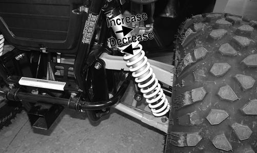
CLEANING AND INSPECTING 1.Completely remove pre-load by turning the adjusters to the end of the threads and removing the retainer; then remove the spring. 2.Clean all shock absorber components in parts-cleaning solvent. 3.Inspect each shock rod for nicks, pits, rust, bends, and oily residue. 4.Inspect all springs, spring retainers, shock rods, sleeves, bushings, shock bodies, and eyelets for cracks, leaks, and bends.
INSTALLING 1.Place the shock absorber spring over the shock absorber, compress the spring, and install the retainer.
2.Place bushings and sleeves (where appropriate) into shock eyelet; then install shocks with two cap screws and nuts.
3.Tighten the front shock absorber cap screws to 40 ft-lb (head side). Tighten the upper rear shock absorber cap screws to 40 ft-lb and the lower rear shock absorber cap screws to 35 ft-lb. 4.Remove the vehicle from the support stand.
CHECKING/ADJUSTING RIDE HEIGHT NOTE: Ensure the vehicle is on level ground, the
tires are properly inflated to 14 psi, and there is an average operating load in the vehicle.
NOTE: When ride height adjustment is required,
raise the vehicle to release all load from the shock absorbers.
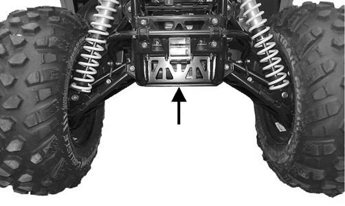
1.Measure from the ground to the bottom of the skid plate along the front sway bar. Measurement should be 10.5 inches.
WT492A
2.If measurement is not as specified, use an appropriate spanner wrench to adjust the left and right spring as required.
WT077B
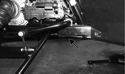
3.Measure from the ground to the bottom of the skid plate along the receiver hitch. Measurement should be 10 inches.
WT590A
4.If measurement is not as specified, use an appropriate spanner wrench to adjust the left and right spring as required.
WT078B
Front A-Arms
REMOVING UPPER 1.Lift and support the vehicle with a support stand to allow access to the front suspension. 2.Remove the front wheels.
3.Remove the cotter pin and hub nut securing the hub.
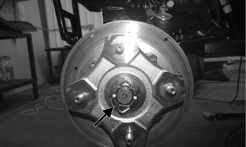
WT328A
4.Remove and discard the “patch-lock” cap screws securing the brake caliper to the hub.
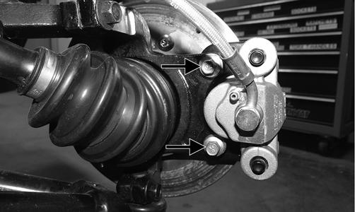
WT287A
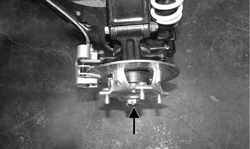
5.Remove the cotter pin and nut securing the tie rod end to the knuckle; then remove the tie rod end from the knuckle.
WT330A
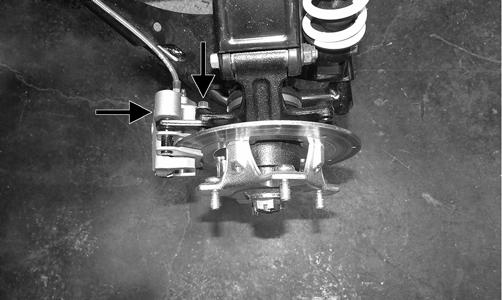
6.Remove and discard the cap screws securing the ball joints to the knuckle.
WT329A
CAUTION
Support the knuckle when removing the cap screws or damage to the threads will occur.
7.Tap the ball joints out of the knuckle; then remove the knuckle.
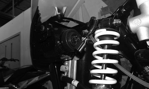
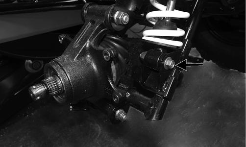
8.Remove and discard the cap screw securing the lower shock eyelet to the upper A-arm. Remove the shock from the A-arm.
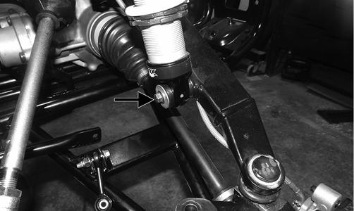
WT498A
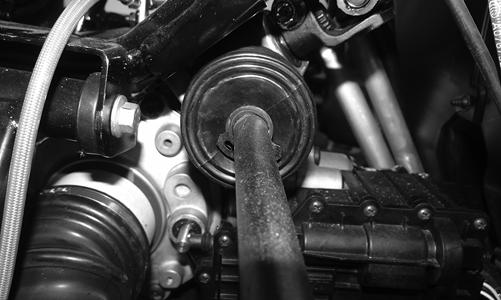
9.Remove the brakeline hose routing clip from the upper A-arm; then remove the cap screw securing the A-arm to the frame. Remove the A-arm.
NOTE: Having the steering rack turned completely
to the left and the clamp orientated as shown will aid in removing the cap screw.
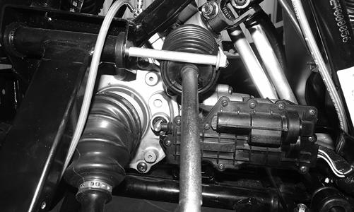
WT334
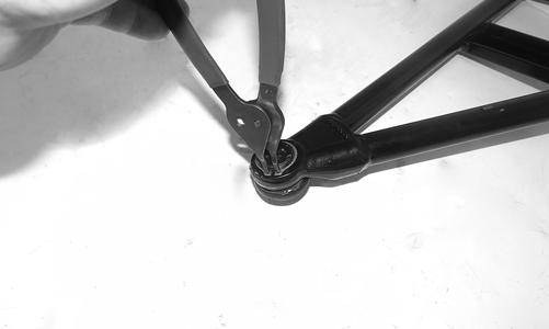
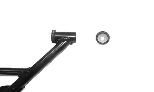
10.Remove the snap ring securing the ball joint in the
A-arm. Remove ball joint.
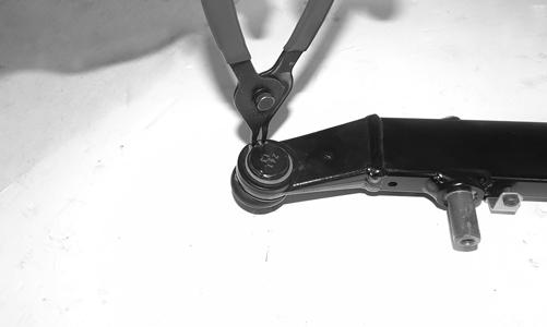
WT496
NOTE: Remove the ball joint only if replacement is
necessary.
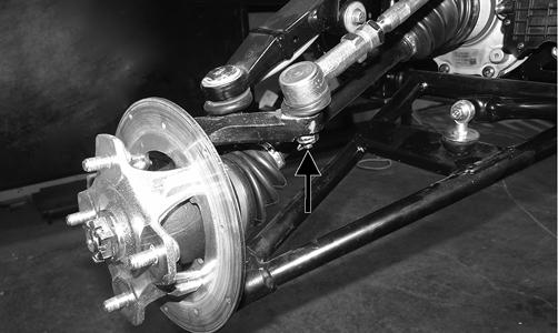
11.Remove and discard the cap screw and lock nut securing the sway bar link to the lower A-arm.
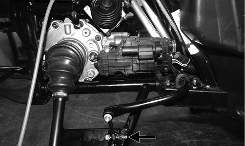
WT494A
12.Remove the seals and sleeve and inspect for cracks, nicks, or tears. NOTE: Remove the bushings only if they must be
serviced.
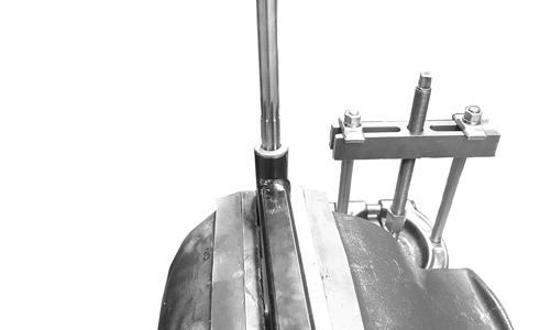
13.Place the A-arm in a bench vise and using an appropriate tool, drive out and discard the bushings.
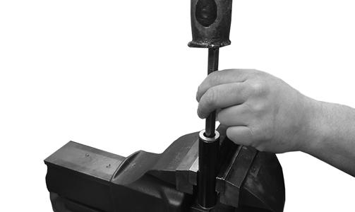
WT600
REMOVING LOWER NOTE: Having the steering rack turned completely
to the left and the clamp orientated as shown will aid in removing the cap screw.
WT333
1.Remove and discard the cap screw and lock nut securing the sway bar link to the lower A-arm.
WT494A
2.Remove the front bumper. NOTE: The front bumper will need to be removed
to remove the lower A-arm cap screw from the frame.
3.Remove the cap screw and discard the lock nut securing the lower A-arm to the frame. Remove the
A-arm.
WT492A
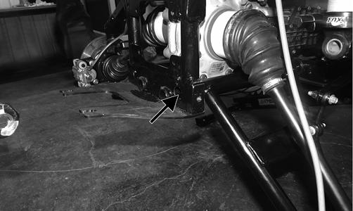
WT493A
4.Remove the seals and sleeve and inspect for cracks, nicks, or tears. NOTE: Remove the bushings only if they must be
serviced.
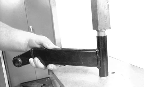
5.Place the A-arm in a bench vise and using an appropriate tool, drive out and discard the bushings.
WT600
CLEANING AND INSPECTING 1.Clean all of the A-arm components in a parts-cleaning solvent. 2.Clean the ball joint opening of all residual Loctite, grease, oil, or dirt. 3.Inspect the A-arms for bends, cracks, and worn bushings. 4.Inspect the ball joint mounting holes for cracks or damage. 5.Inspect the frame mounts for signs of damage, wear, or weldment damage.
INSTALLING 1.Using a suitable press, press in the new bushing.
WT599
2.Place the A-arm in a bench vise and using a 16 mm reamer, ream out the bushings.
WT596
3.Insert the sleeve into the A-arm and apply molybdenum grease to the inside of the seals. Install the seals on the A-arm.
4.Apply Loctite Primer “T” to the A-arm socket; then apply Green Loctite #609 to the entire outside diameter of the ball joint. Install the ball joint into the
A-arm and secure it with the snap ring.
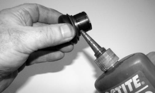
WC237
WT497
5.Install the lower A-arm into the frame mounts and secure it with the cap screw and new lock nut. Finger-tighten only at this time. 6.With a new “patch-lock” cap screw and new lock nut, secure the sway bar link to the lower A-arm.
Tighten to 20 ft-lb.
WT494A
7.Tighten the lower A-arm cap screw to 40 ft-lb. 8.Install the upper A-arm to the frame with the cap screw and new lock nut. Finger-tighten only at this point.
WT334
9.Route the brakeline hose underneath the upper
A-arm and secure it with the clip. Tighten to 30 in.-lb.
10.Install the knuckle on the lower ball joint using a new “patch-lock” cap screw. Finger-tighten only at this time. With the axle going through the center of the knuckle, rotate it upward and secure the upper
A-arm to the knuckle using a new “patch-lock” cap screw. Tighten the cap screws to 35 ft-lb.
WT332
11.Install the tie rod end and secure it with the castle nut (coated with red Loctite #271). Tighten to 55 ft-lb; then install a new cotter pin and spread the pin to secure the nut.
WT330A
12.Install the hub assembly and secure it with the hub nut. Tighten to 200 ft-lb and install the new cotter pin. Spread the pin to secure the nut.
WT328A
NOTE: During assembly, new cotter pins should
always be used.
NOTE: If the cotter pin cannot be inserted due to
misalignment of the hole and the slots in the nut, always tighten the nut until it is properly aligned.
13.Using a new “patch-lock” cap screw and existing washer, secure the shock to the upper A-arm. Tighten to 25 ft-lb.
WT498A
14.Tighten the cap screw securing the upper A-arm to the frame to 35 ft-lb.
15.Using new “patch-lock” cap screws, secure the brake caliper to the brake disc. Tighten to 20 ft-lb.
WT287A
16.Install the wheels and tighten the wheel nuts in 20 ft-lb increments to a final torque of 40 ft-lb (steel wheel), 60 ft-lb (aluminum wheel w/black nuts), or 80 ft-lb (aluminum wheel w/chrome nuts). 17.Install the front bumper; then remove the vehicle from the support stand.
REMOVING 1.Lift and support the vehicle on a support stand that allows access to the rear suspension with the rear tires off of the floor. Remove the wheels.
NOTE: The upper A-arm can be removed without
removing the hub or the knuckle. If it is the technician’s objective to only remove the upper A-arm, proceed to step 5.
2.Remove and discard the “patch-lock” cap screws securing the brake caliper to the hub.
WT418A
3.Remove and discard the cotter pin from the hub nut; then remove nut and hub.
WT418B
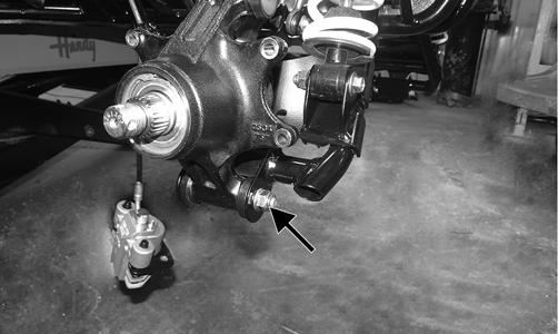
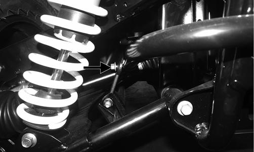
4.Remove the lower shock cap screw and discard the nut.
WT447A
6.Remove the cap screw securing the lower A-arm to the hub. Discard the nut.
W446A
NOTE: The drive axle does not need to be removed
for this procedure.
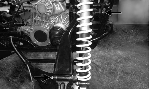
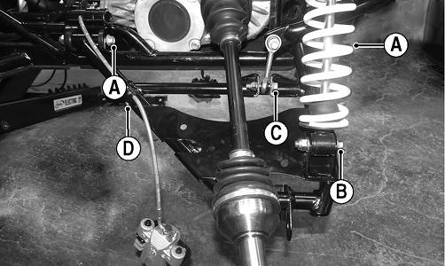
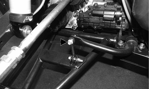
7.Remove and discard the cap screw and lock nut securing the sway bar link to the lower A-arm (A).
Remove the cap screw and clip securing the brake line to the lower A-arm (B); then remove the cap screw and nut securing the shock to the lower A-arm (C).
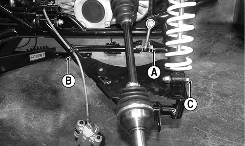
WT448A
8.Remove the cap screws and nuts securing the lower
A-arm to the frame. Discard the nuts.
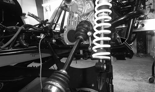
WT445A
9.Remove the seals and sleeve.
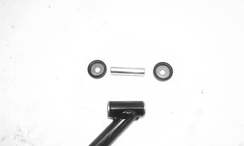
WT444
NOTE: Remove the bushings only if they must be
serviced.
10.Place the A-arm in a bench vise and using an appropriate tool, drive out and discard the bushings.
WT600
CLEANING AND INSPECTING 1.Clean all A-arm components in parts-cleaning solvent.
2.Inspect the A-arm for bends, cracks, and worn bushings. 3.Inspect the frame mounts for signs of damage, wear, or weldment damage.
INSTALLING NOTE: If only the upper A-arm was removed, skip
to step 6.
1.Using a suitable press, press in the new bushing.
WT599
2.Place the A-arm in a bench vise and using a 16 mm reamer, ream out the bushings.
WT596
3.Insert the sleeve into the A-arm; then apply grease to the seal and insert it into the end of the A-arm along with the end caps.
WT449
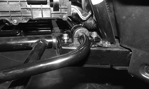
4.Install the lower A-arm into the frame mount and secure with cap screws and new lock nuts (A). Only finger tighten at this point. Install the shock into the lower A-arm and secure it with the cap screw and new lock nut (B). Only finger tighten at this point.
Install the sway bar link into the lower A-arm and secure it with the new “patch-lock” cap screw and lock nut (C). Only finger tighten at this point. Install the cap screw and clip securing the brake line to the lower A-arm (D).
WT448B
5.Tighten cap screw (A) to 35 ft-lb, cap screw (B) to 35 ft-lb, cap screw (C) to 20 ft-lb, and cap screw (D) to 20 in.-lb.
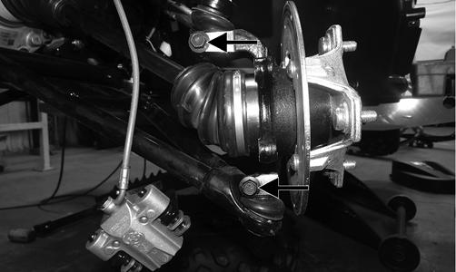
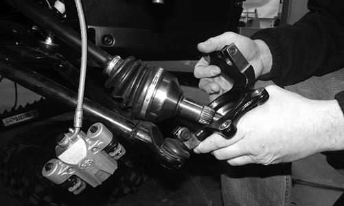
6.Using the existing cap screws and new lock nuts, secure the knuckle to the upper and lower A-arms.
Tighten to 35 ft-lb. NOTE: It is important that the hub is installed in a
manner that allows you to read the text.
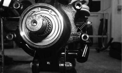
WT450A
7.If the upper A-arm was removed, insert the sleeve into the end of the upper A-arm. Apply grease to the seals and install into the A-arm.
WT449
8.Install the upper A-arm into the frame. Mount and secure the hub with the cap screws and new locking nuts.
9.Install the hub assembly and using an appropriate spanner wrench, secure the hub to the axle with the castle nut. Tighten to 200 ft-lb.
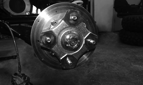
WT451
10.Install a new cotter pin and spread the pin to secure the nut.
NOTE: If the pin does not line up with the castle
nut, always tighten the nut to the next opening and install the pin.
11.Using new “patch-lock” cap screws, install the brake caliper and tighten to 20 ft-lb. 12.Install the wheels and tighten the wheel nuts in 20 ft-lb increments to a final torque of 40 ft-lb (steel wheel), 60 ft-lb (aluminum wheel w/black nuts), or 80 ft-lb (aluminum wheel w/chrome nuts). 13.Remove the vehicle from the stand.
Front Sway Bar
REMOVING 1.Remove the front wheels (see Wheels and Tires in this section). 2.Remove and discard the cap screws and lock nuts securing the sway bar to the A-arm links.
WT323A
3.Remove the sway bar bushing retainers and bushings and slide the sway bar out of the vehicle.
INSPECTING 1.Inspect the sway bar for any signs of twisting or cracking. 2.Inspect the bushing retainers and bushings for any signs of wear or damage.
INSTALLING 1.Using new “patch-lock” cap screws and new lock nuts, install the sway bar into position and secure it to the lower A-arm links.
2.Install the bushing retainers and bushings. Finger-tighten the cap screws only at this point.
WT324
3.Tighten the A-arm links to 20 ft-lb; then tighten the sway bar link to 35 ft-lb.
Rear Sway Bar
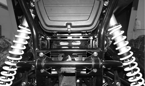
REMOVING 1.Remove and discard the cap screws and lock nuts securing the sway bar link to the lower A-arms on both sides.
WT320A
2.Remove the cap screws securing the sway bar to the frame and remove the sway bar. Account for the bushing retainers and bushings.
INSPECTING 1.Inspect the sway bar for any signs of twisting or cracking. 2.Inspect the bushing retainers and bushings for any signs of wear or damage.
INSTALLING 1.Using new “patch-lock” cap screws and new lock nuts, secure the sway bar to the lower A-arm link.
Finger-tighten only at this point. 2.Install the bushings and bushing retainers. Finger-tighten only at this point. 3.Tighten the lower A-arm links to 20 ft-lb; then tighten the sway bar link to 35 ft-lb.
Wheels and Tires
TIRE SIZE
! WARNING
Use only Arctic Cat approved tires when replacing tires. Failure to do so could result in unstable vehicle operation.
The Wildcat Trail is equipped with low-pressure tubeless tires of the size and type listed in General Information. Do not under any circumstances substitute tires of a different type or size.
! WARNING
Always use the size and type of tires specified. Always maintain proper tire inflation pressure.
CAUTION
Do not mix tire tread patterns. Use the same pattern type on front and rear. Failure to heed warning could cause poor handling qualities of the vehicle and could cause excessive drive train damage not covered by warranty.
TIRE INFLATION PRESSURE Front and rear tire inflation pressure should be as specified in the General Information/Foreword section.
REMOVING 1.Secure the vehicle on a support stand to elevate the wheels.
2.Remove the nuts securing the wheels; then remove the wheels.
CLEANING AND INSPECTING 1.Clean the wheels and hubs with parts-cleaning solvent.
2.Clean the tires with soap and water. 3.Inspect each wheel for cracks, dents, or bends. 4.Inspect each tire for cuts, wear, missing lugs, and leaks.
INSTALLING Install the wheels and tighten the wheel nuts in 20 ft-lb increments to a final torque of 40 ft-lb (steel wheel), 60 ft-lb (aluminum wheel w/black nuts), or 80 ft-lb (aluminum wheel w/chrome nuts).
CHECKING/INFLATING 1.Using an air pressure gauge, measure the air pressure in each tire. Adjust the air pressure as necessary to meet the recommended inflation pressure. 2.Inspect the tires for damage, wear, or punctures. ! WARNING
Do not operate the vehicle if tire damage exists.
NOTE: If repair is needed, follow the instructions
found on the tire repair kit or replace the tire.
Troubleshooting
Problem: Suspension too soft Condition Remedy
1. Spring preload incorrect 1.Adjust preload 2. Spring(s) weak 2.Replace spring(s) 3. Shock absorber damaged 3.Replace shock absorber
Problem: Suspension too stiff Condition Remedy
1. Spring preload incorrect 1.Adjust preload 2. A-arm-related bushings worn 2.Replace bushing
Problem: Suspension noisy Condition Remedy
1. Cap screws (suspension system) loose 1.Tighten cap screws 2. A-arm-related bushings worn 2.Replace bushings
Problem: Vehicle pulling or steering erratic Condition Remedy
1. Vehicle steering is erratic on dry, level surface 1.Check front wheel alignment and adjust if necessary (see Steering/Body/Controls) 2. Vehicle pulls left or right on dry, level surface 2.Check air pressure in tires and adjust to specifications